SATO PV4 Service Manual
Hide thumbs
Also See for PV4:
- Driver installation manual (11 pages) ,
- User manual (36 pages) ,
- Manual (43 pages)
Table of Contents
Advertisement
Advertisement
Table of Contents

Related Manuals for SATO PV4


Summary of Contents for SATO PV4
- Page 1 Service Manual BARCODE PRINTER Ver. 1.00...
-
Page 2: Table Of Contents
3-3 Accessories Specifications ..................31 3-3-1 Accessories Classification .................. 31 3-3-2 Accessories Appearance ..................32 3-3-3 WWPV45010 Lithium ion Battery for PV4 Smart ..........33 3-3-4 WWPV95950 PV AC/DC AdaptorS W/O PC ............33 3-3-5 WWPV99310 PV 1CH Battery Cradle ASSY ............33 3-3-6 WWPV95360 PV 1CH BC AdaptorA W/O Power cord ........ - Page 3 5. Disassembly and Exploded view ................38 5-1 Disassembly ......................38 5-1-1 ASSY-TOTAL Disassembly ................. 38 5-1-2 ASSY-COVER-LOWER disassembly ..............40 5-1-3 ASSY-COVER-PAPER disassembly ..............41 5-1-4 ASSY-HOLDER-PLATEN disassembly ............... 42 5-1-5 ASSY-PEELER disassembly ................43 5-1-6 ASSY-SUB-COVER-LOWER disassembly ............44 5-1-7 ASSY-TERMINAL disassembly ................
-
Page 4: Precaution Segment
1. Precaution Segment 1-1 Safety Precautions 1. Make sure that there are no cabinet openings through which people – particularly children – might insert fingers and contact dangerous voltages. Such openings include excessively wide cabinet ventilation slots and improperly fitted covers and drawers. 2. -
Page 5: Servicing Precaution
1-2 Servicing Precaution WARNING 1: First read the Safety Precaution section of this manual. If some unforeseen circumstance creates a conflict between the servicing and safety precautions, always follow the safety precaution. WARNING 2: An electrolytic capacitor installed with the wrong polarity might explode. 1. -
Page 6: Precaution For Electrostatically Sensitive Devices (Esds)
1-3 Precaution for Electrostatically Sensitive Devices (ESDs) 1. Some semiconductor (solid state) devices are easily damaged by static electricity. Such components are called electrostatically sensitive devices (ESDs); examples include integrated circuits and some field-effect transistors. The following techniques will reduce the occurrence of component damaged caused by static electricity. -
Page 7: Battery Safety Warning
1-5 Battery Safety Warning Please be sure to read this guide prior to use. Warning 1. If the battery is not charged after the charging time, stop charging and contact the seller. 2. Store and use the battery where it will not come into contact with liquid (water, salt water, etc.). There may be a risk of overheating, rupturing or igniting. - Page 8 Recommendations 1. Do not charge for longer than the charging time described in this guide, as it may reduce battery performance and duration. 2. If the battery is not expected to be used for a long time, remove it from the equipment and keep in a place with low humidity.
-
Page 9: Installation & Usage
Reinstall Battery The printer may incur serious damage if the AC/DC adaptor provided by SATO is not used. SATO is not legally liable for any such damages. Caution (The voltage and electrical current specifications of the printer and battery charger must match.) -
Page 10: Using 1Ch Battery Charger (Optional)
SATO when using a single battery charger. SATO is not legally liable for any such damages. Caution - You must use the battery charger power supply provided by SATO to use the single battery charger. (AC/DC adaptor is not available) 2-2-3 Using 4CH Battery Charger (Optional) - Page 11 2-2-3-2 Charging Battery 1) Insert the battery into the 4CH Battery Charger as shown in the figure on the left. 2) Gently slide the battery until it reaches the bottom of the charger. 3) Charging starts as soon as the battery is completely inserted.
-
Page 12: Paper Installation
2-3 Paper Installation 1) Press the Open button to open the paper cover. 2) Insert the paper as shown. (Remove the empty core.) 3) Align the paper as shown. 4) Pull out the paper as shown and close the paper cover. - 12 - Ver. -
Page 13: Using Peeler
NOTE The specification of the paper inner diameter of the standard paper disks are 19 mm (0.75 inch). If you are using paper with a smaller inner diameter, remove the paper disks as shown below and replace it with the supplied 12 mm (0.47 inch) paper disks. -
Page 14: Using Belt Strap
2-5 Using Belt Strap 1) Insert the belt strap screw into the belt strap hole. Belt Strap 2) Use a coin to tighten the belt strap screw Coin as shown in the image. 3) Unfasten the belt strap Velcro. Belt 4) Slide the belt strap over a belt. -
Page 15: Using Fan-Fold Paper
2-6 Using Fan-Fold Paper 1-1) After keeping the paper holder open wide (as shown), hold the paper holder by lifting right guide holder as shown in the figure. NOTE Use only when you are using 105 mm (4.13 inch) paper. 1-2) After keeping the paper holder wide (as shown), hold the paper holder by lifting left guide holder as shown in the figure. -
Page 16: Using Control Panel
2-7 Using Control Panel • Power Button This button is used to turn the printer on, off, to move to main menu or to operate the action. 1) When the printer is off, press this button for approximately 2 seconds to turn on the power. 2) When the printer is on, press this button for approximately 2 seconds to turn off the power. -
Page 17: Recommended Papers
2-9 Recommended Papers Please contact your local SATO office for media recommendation. - 17 - Ver. 1.00... -
Page 18: Self Test
4) After the wireless interface information is printed, the self-test is automatically terminated. • Self-Test Sample SATO PV4 CONFIGURATION FIRMWARE VERSION : V01.00 STD 010118 EMULATION : SLCS & BPL-Z & BPL-C PRINT DARKNESS... - Page 19 RF INTERFACE STATUS (BT) RF INTERFACE STATUS (WLAN) BLUETOOTH F/W VER : 2.0.4 WLAN F/W VER : 02.02(4002) MAC ADDRESS MAC ADDRESS FRIENDLY NAME : PV4 SYSTEM NAME : PV4 MODE : CLASSIC NETWORK MODE : SOFT AP AUTH & ENCRYPT : ENABLED FREQUENTY : (PRIORITY)2.4GHZ/5GHZ...
-
Page 20: Lcd Menu
2-11 LCD Menu You can check printer status and setting information through LCD. • Top icon Icon Description Bluetooth is enabled but not connected to the host device Bluetooth is enabled and connected to the host device Display signal strength of wireless LAN Can not searching the registered AP Authentication failed LAN is enabled and connected... - Page 21 • Main menu icon Icon Description Check / set the status of whole printer 1) Interface 2) Media 3) Sensor 4) Powersave 5) Language Media settings 1) Density 2) Position - Tear off - Print - Direction Tools 1) Hex dump 2) Print printer config ...
- Page 22 Icon Description Check printer information 1) Version - Printer, WLAN, Bluetooth 2) Bluetooth 3) WLAN 4) LAN 5) Battery 6) Repair Sensor settings 1) Media type - Auto detection / Rear black mark / Gap - Continueous 2) Peeler - On/Off - Sensor sensitivity adjustment Set Backlight, Sleep and Power off Time 1) Backlight brightness...
-
Page 23: Peripherals Connection
2-12 Peripherals Connection This product can communicate with other devices via Bluetooth, Wireless LAN communication and cable. 2-12-1 Bluetooth, Wireless LAN Connection 1) The printer can be connected to devices equipped with Bluetooth communication capacity (PDAs, PCs, etc.). 2) Use the Bluetooth connection function supported by the device to connect to the printer. -
Page 24: Interface Cable Connection
(PDAs, PCs, etc.). NOTE The interface cable for the printer is either a Serial/USB cable provided by SATO (optional) or USB Type-C cable supporting USB2.0. USB Type-C connection Power connection Serial/USB 14pin connection (for the cable provided by SATO(optional)) - 24 - Ver. -
Page 25: Fixed Interface Cable Connection
③ as shown in the figure. 4) Connect the interface cable to the USB port of the device (PDAs, PCs, etc.). NOTE The fixed interface cable that can be connected to the printer is a Serial/USB cable provided by SATO(optional). - 25 - Ver. 1.00... -
Page 26: Product Specifications
3. Product Specifications 3-1 General Specifications Item Description Printing Method Direct Thermal Print Speed Up to 5 ips Resolution 203 dpi 10 SLCS Resident Bitmap Fonts One SLCS Resident Scalable Font 16 BPL-Z™ Resident Bitmap Fonts Font One BPL-Z™ Resident Scalable Font 7 BPL-C™... -
Page 27: Printer Specifications
W= W-LAN L=Linerless Bi= Bluetooth Part Number Description Remark WWPV41281 PV4 STD USB2.0+Serial+WLAN+Bluetooth5.0 MFi BLE for US WWPV41271 PV4 STD USB2.0+Serial+WLAN for US WWPV41261 PV4 STD USB2.0+Serial+Bluetooth5.0 MFi BLE for US WWPV41282 PV4 STD USB2.0+Serial+WLAN+Bluetooth5.0 MFi BLE for EU WWPV41272 PV4 STD USB2.0+Serial+WLAN for EU... -
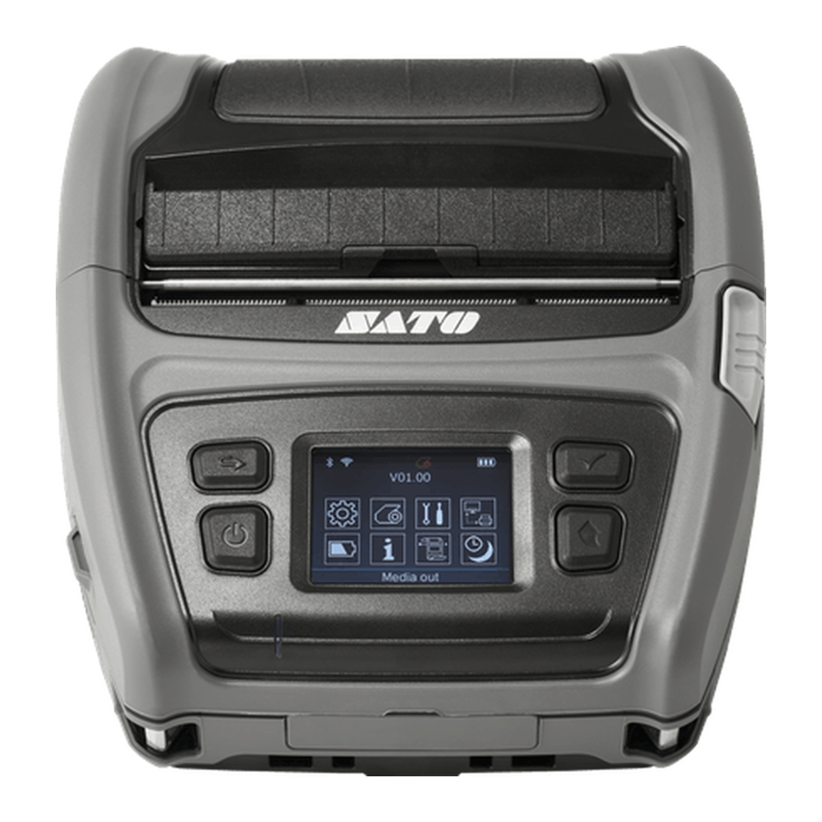
Page 28: Printer Appearance
3-2-3 Printer Appearance 3-2-3-1 Printer Dimensions - 28 - Ver. 1.00... - Page 29 3-2-3-2 Feature Locations • Front • Rear - 29 - Ver. 1.00...
-
Page 30: Other Component Specifications
3-2-4 Other Component Specifications Item Description Heat element structure 2 heaters/dot Number of heat elements 832 dots Heat element pitch 8.0 dots/mm (0.125 mm pitch) Print width 104 ± 0.2 mm 142Ω ± 4 % Average resistance value (R Voltage 11.5 VDC(Standard Opearating) Phase 2 Phase... -
Page 31: Accessories Specifications
3-3 Accessories Specifications 3-3-1 Accessories Classification Product code Description Remark WWPV95600 Belt Strap for PV 10P WWPV45010 Lithium ion Battery for PV4 Smart WWPV95951 PV AC/DC AdaptorS for US New! STH Product WWPV95952 PV AC/DC AdaptorS for EU New! STH Product WWPV95953... -
Page 32: Accessories Appearance
3-3-2 Accessories Appearance - 32 - Ver. 1.00... -
Page 33: Wwpv45010 Lithium Ion Battery For Pv4 Smart
3-3-3 WWPV45010 Lithium ion Battery for PV4 Smart Item Description Cell type Lithium-ion Charging voltage 8.4VDC Input Charging current 0.8A ± 10% Charging time 6 hours Voltage 7.2VDC (Available 8.4~6.0VDC) Output Capacity 6700 mAh 3-3-4 WWPV95950 PV AC/DC AdaptorS W/O PC... -
Page 34: Wwpv93700, Wwpv93750 Interface Cable For Pc
3-3-9 WWPV93700, WWPV93750 Interface cable for PC 1) WWPV93700 Serial cable connection for PC (TXD) 1 2 (RXD) (RXD) 2 (RTS) 3 3 (TXD) (CTS) 4 4 (DTR) (GND) 5 Host side (N C) 6 5 (GND) (9Pin) Printer (N C) 7 side 6 (DSR) (14Pin) - Page 35 3) Connector signal descriptions Pin No. Signal name Direction Function Output Transmit data Input Receive data Request to send Input Set high when printer is ready to accept a command or data Output Clear to send from host Ground Differential data line Differential data line Ground CABLE_DET...
-
Page 36: Type-C Usb Interface Cable For Pc
3-3-10 TYPE-C USB Interface cable for PC 1) TYPE-C USB cable connection for PC 2) Connector signal descriptions Pin No. Signal name Direction Function A4,A9,B4,B9 VBUS Input VBUS(Power Delivery 9Vdc) EMER_HOLD Input USB, Emergency Power Control Switch Input Configuration channel Non-SuperSpeed differential pair, position 1,2, A7,B7 negative... -
Page 37: Hardware
4. Hardware 4-1 Wiring diagram 4-1-1 Main board TOP wiring diagram 4-1-2 Main board BOTTOM wiring diagram - 37 - Ver. 1.00... -
Page 38: Disassembly And Exploded View
5. Disassembly and Exploded view 5-1 Disassembly 5-1-1 ASSY-TOTAL Disassembly - 38 - Ver. 1.00... - Page 39 Part name Disassembly procedure (1) ASSY-COVER-LOWER 1) Separate the (10) BATTERY (2) ASSY-TERMINAL 2) Remove the six (11) SCREWs (3) ASSY-PCB-MAIN 3) Separate the (4) ASSY-COVER-UPPER from the ASSY-COVER-LOWER (4) ASSY-COVER-UPPER 4) Remove the six (11) SCREWs (5) COVER-CAP-TERMINAL 5) Separate the (8) ASSY-FRAME-MAIN-NR and the (9) ASSY-FRAME-PAPER (6) COVER-CAP-FANFOLD from the ASSY-COVER-LOWER (7) COVER-CAP-USB-14...
-
Page 40: Assy-Cover-Lower Disassembly
5-1-2 ASSY-COVER-LOWER disassembly Part name Disassembly procedure (1-1-1) ASSY-COVER-PAPER 1) Remove the two (1-1-5) SCREWs. (1-1-2) ASSY-SUB-COVER-LOWER 2) Separate the (1-1-3) COVER-PIVOT-L and the (1-1-4) COVER-PIVOT-R (1-1-3) COVER-PIVOT-L and the (1-1-6) SHAFT-PIVOT and the (1-1-1) ASSY-COVER-PAPER (1-1-4) COVER-PIVOT-R from the (1-1-2) ASSY-SUS-COVER-LOWER. (1-1-5) SCREW-TAPPING (1-1-6) SHAFT-PIVOT - 40 -... -
Page 41: Assy-Cover-Paper Disassembly
5-1-3 ASSY-COVER-PAPER disassembly Part name Disassembly procedure (1-1-1-1) COVER-PAPER-NFC 1) Remove the four (1-1-1-4) SCREWs. (1-1-1-2) NFC TAG+TAPE 2) Remove the tow (1-1-1-10) SCREWs (1-1-1-3) ASSY-HOLDER-PLATEN 3) Separate the (1-1-1-6) COVER-PAPER-WINDOW (1-1-1-4) SCREW-TAPPING from the (1-1-1-1) COVER-PAPER-NFC (1-1-1-5) ASSY-PEELER 4) Separate the (1-1-1-7) LABEL-NFC-COVER and the (1-1-1-9) LABEL-PAPER (1-1-1-6) COVER-PAPER-WINDOW from the (1-1-1-6) COVER-PAPER-WINDOW (1-1-1-7) LABEL-NFC-COVER... -
Page 42: Assy-Holder-Platen Disassembly
5-1-4 ASSY-HOLDER-PLATEN disassembly Part name Disassembly procedure (1-1-1-3-1) HOLDER-PLATEN-A 1) Remove the (1-1-1-3-9) SCREW (1-1-1-3-2) ASSY-PLATEN-ROLLER 2) Separate the (1-1-1-3-7) HOLDER-PLATEN-CAP (1-1-1-3-2-1) PLATEN-ROLLER and the (1-1-1-3-6) SHAFT-PEELER-PIVOT (1-1-1-3-2-2) BUSH-PLATEN-ROLLER and the (1-1-1-3-2) ASSY-PLATEN-ROLLER (1-1-1-3-2-3) GEAR-FEEDING from the (1-1-1-3-1) HOLDER-PLATEN-A. (1-1-1-3-2-4) RING-E 3) Separate the (1-1-1-3-2-3) GEAR-FEEDING (1-1-1-3-3) ASSY-PCB-BM and the (1-1-1-3-2-4) RING-E and the two (1-1-1-3-2-2) BUSH-PLATEN-ROLLER... -
Page 43: Assy-Peeler Disassembly
5-1-5 ASSY-PEELER disassembly Part name Disassembly procedure (1-1-1-5-1) PEELER-HOUSING 1) Remove the two (1-1-1-5-10) SCREWs. (1-1-1-5-2) PEELER-ROLLER 2) Separate the two (1-1-1-5-7) PEELER-LOCKING-CAP (1-1-1-5-3) PEELER-HOLDER-ROLLER and the two (1-1-1-5-6) SHAFT-PEELER-LOCKING (1-1-1-5-4) PEELER-HOLDER-SPRING and the two (1-1-1-5-8) SPRING-PEELER-LOCKING (1-1-1-5-5) SPRING-PEELER-ROLLER from the (1-1-1-5-1) PEELER-HOUSING (1-1-1-5-6) SHAFT-PEELER-LOCKING 3) Remove the three (1-1-1-5-11) SCREWs. -
Page 44: Assy-Sub-Cover-Lower Disassembly
5-1-6 ASSY-SUB-COVER-LOWER disassembly Part name Disassembly procedure (1-1-2-1) ASSY-COVER-LOWER 1) Remove the two (1-1-2-3) SCREWs. (1-1-2-2) HOUSING-HOLDER-STRAP 2) Separate the (1-1-2-4) SPRING-ESD (1-1-2-3) SCREW-TAPPING and the two (1-1-2-2) HOUSING-HOLDER-STRAP (1-1-2-4) SPRING-ESD from the (1-1-2-1) ASSY-COVER-LOWER. - 44 - Ver. 1.00... -
Page 45: Assy-Terminal Disassembly
5-1-7 ASSY-TERMINAL disassembly Part name Disassembly procedure (2-1) ASSY-PCB-TERMINAL-FFC 1) Remove the four (2-5) SCREWs. (2-2) FFC-BLUETOOTH 2) Separate the (2-6) WIRE-HARNESS (2-3) TERMINAL-LOWER and the (2-3) TERMINAL-LOWER (2-4) ASSY-TERMINAL-UPPER and the (2-1) ASSY-PCB-TERMINAL-FFC (2-5) SCREW-TAPPING and the (2-2) FFC-BLUETOOTH (2-6) WIRE-HARNESS from the (2-4) ASSY-TERMINAL-UPPER - 45 -... -
Page 46: Assy-Cover-Upper Disassembly
5-1-8 ASSY-COVER-UPPER disassembly - 46 - Ver. 1.00... - Page 47 Part name Disassembly procedure (4-1-1) ASSY-COVER-UPPER 1) Remove the (4-1-8) SCREW (4-1-2) COVER-BUTTON-OPEN 2) Separate the (4-1-5) HOLDER-BUTTON-OPEN (4-1-3) COVER-LCD-WINDOW and the (4-1-2) COVER-BUTTON-OPEN and the (4-1-6) SP-BUTTON (4-1-4) RUBBER-BUTTON-LCD from the (4-1-1) ASSY-COVER-UPPER (4-1-5) HOLDER-BUTTON-OPEN 3) Remove the five (4-1-8) SCREWs (4-1-6) SP-BUTTON 4) Separate the (4-1-7) ASSY-PCB-LCD-CONTROL-H-FFC (4-1-7) ASSY-PCB-LCD-CONTROL-H-FFC...
-
Page 48: Assy-Frame-Main-Nr Disassembly
5-1-9 ASSY-FRAME-MAIN-NR disassembly - 48 - Ver. 1.00... - Page 49 Part name Disassembly procedure (8-1) ASSY-SUB-FRAME MAIN 1) Remove the two (8-11) SCREWs (8-2) ASSY-PCB-PE-HARNESS 2) Separate the (8-7) ASSY-SENSOR-PEELER from the (8-6) HOUSING-TPH (8-3) HOLDER-SENSOR-PE 3) Remove the two (8-11) SCREWs (8-4) SCREW-TAPPING 4) Separate the (8-6) HOUSING-TPH and the (8-5) ASSY-TPH-R (8-5) ASSY-TPH-R and the (8-16) SPRING-TPH from the (8-1) ASSY-SUB-FRAME MAIN (8-6) HOUSING-TPH...
-
Page 50: Assy-Sub-Frame Main Disassembly
5-1-10 ASSY-SUB-FRAME MAIN disassembly Part name Disassembly procedure (8-1-1) FRAME-MAIN-A 1) Separate the (8-1-3) ASSY-ARM-LOCKING-L (8-1-2) LABEL-HOT-PE and the (8-1-4) ASSY-ARM-LOCKING-R and the (8-1-2) LABEL-HOT-PE (8-1-3) ASSY-ARM-LOCKING-L from the (8-1-1) FRAME-MAIN-A (8-1-4) ASSY-ARM-LOCKING-R - 50 - Ver. 1.00... -
Page 51: Assy-Arm-Locking-L Disassembly
5-1-11 ASSY-ARM-LOCKING-L disassembly Part name Disassembly procedure (8-1-3-1) ARM-LOCKING-L 1) Remove the (8-1-3-5) SCREW (8-1-3-2) SPRING-LOCKING 2) Separate the (8-1-3-3) ARM-LOCKING-L-CAP and the (8-1-3-2) SPRING-LOCKING (8-1-3-3) ARM-LOCKING-L-CAP and the (8-1-3-1) ARM-LOCKING-L from the (8-1-3-4) SHAFT-LOCKING (8-1-3-4) SHAFT-LOCKING (8-1-3-5) SCREW-TAPPING - 51 - Ver. -
Page 52: Assy-Arm-Locking-R Disassembly
5-1-12 ASSY-ARM-LOCKING-R disassembly Part name Disassembly procedure (8-1-4-1) ARM-LOCKING-R 1) Remove the two (8-1-4-4) SCREWs (8-1-4-2) BRACKET-ARM-LOCKING-R 2) Separate the (8-1-4-2) BRACKET-ARM-LOCKING-R (8-1-4-3) WIRE-HARNESS and the (8-1-4-3) WIRE-HARNESS and the (4-1-6) SP-BUTTON (8-1-4-4) SCREW-TAPPING from the (8-1-4-1) ARM-LOCKING-R - 52 - Ver. -
Page 53: Assy-Tph-R Disassembly
5-1-13 ASSY-TPH-R disassembly Part name Disassembly procedure (8-5-1) HEAD-PRINTER 1) Remove the two (8-5-6) SCREWs (8-5-2) TAPE-TPH 2) Separate the (8-5-5) FPC-MAIN (8-5-3) HEATSINK-R from the (8-5-4) HOUSING-HEATSINK (8-5-4) HOUSING-HEATSINK 3) Remove the two (8-5-6) SCREWs (8-5-5) FPC-MAIN 4) Separate the (8-5-3) HEATSINK-R and the (8-5-7) CUSHION-TPH (8-5-6) SCREW-TAPPING and the (8-5-1) HEAD-PRINTER and the (8-5-2) TAPE-TPH (8-5-7) CUSHION-TPH... -
Page 54: Assy-Sensor-Peeler Disassembly
5-1-14 ASSY-SENSOR-PEELER disassembly Part name Disassembly procedure (8-7-1) BRACKET-CUTTER-MANUAL 1) Remove the two (8-7-6) SCREWs (8-7-2) HOLDER-SENSOR-PEELER 2) Separate the (4-1-2) COVER-BUTTON-OPEN (8-7-3) ASSY-PCB-PRESENCE-HARNESS and the (8-7-3) ASSY-PCB-PRESENCE-HARNESS (8-7-4) GUIDE-BACKFEED from the (8-7-2) HOLDER-SENSOR-PEELER (8-7-5) SPRING-BACKFEED 3) Remove the two (8-7-6) SCREWs (8-7-6) SCREW-TAPPING 4) Separate the (8-7-2) HOLDER-SENSOR-PEELER and the two (8-7-5) SPRING-BACKFEED and the two (8-7-4) GUIDE-BACKFEED... -
Page 55: Assy-Frame-Paper Disassembly
5-1-15 ASSY-FRAME-PAPER disassembly - 55 - Ver. 1.00... - Page 56 Part name Disassembly procedure (9-1) FRAME-PAPER 1) Remove the two (9-12) SCREWs (9-2) PAPER-LOCKING-L 2) Separate the (9-2) PAPER-LOCKING-L and the (9-3) PAPER-LOCKING-R (9-3) PAPER-LOCKING-R and the (9-4) PAPER-LOCKING-L-CAP and the (9-5) PAPER-LOCKING-R-CAP (9-4) PAPER-LOCKING-L-CAP from the (9-1) FRAME-PAPER (9-5) PAPER-LOCKING-R-CAP 3) Remove the four (9-12) SCREWs (9-6) ASSY-PAPER-HOLDER-L-19 4) Separate the (9-11) BRACKET-FRAME-PAPER...
-
Page 57: Assy-Paper-Holder-L-19 Disassembly
5-1-16 ASSY-PAPER-HOLDER-L-19 disassembly Part name Disassembly procedure (9-6-1) PAPER-HOLDER-DISK-L 1) Remove the (9-6-7) SCREW (9-6-2) PAPER-DISK-CAP-INNER 2) Separate the (9-6-5) PAPER-DISK-19 and the (9-6-2) PAPER-DISK-CAP-INNER (9-6-3) PAPER-DISK-CAP-OUTER from the (9-6-1) PAPER-HOLDER-DISK-L (9-6-4) BEARING-ROLLER 3) Remove the two (9-6-6) SCREWs (9-6-5) PAPER-DISK-19 4) Separate the (9-6-3) PAPER-DISK-CAP-OUTER and the (9-6-4) BEARING-ROLLER (9-6-6) SCREW-TAPPING from the (9-6-1) PAPER-HOLDER-DISK-L... -
Page 58: Assy-Paper-Holder-R-19 Disassembly
5-1-17 ASSY-PAPER-HOLDER-R-19 disassembly Part name Disassembly procedure (9-6-2) PAPER-DISK-CAP-INNER 1) Remove the (9-7-5) SCREW (9-6-3) PAPER-DISK-CAP-OUTER 2) Separate the (9-6-5) PAPER-DISK-19 and the (9-6-2) PAPER-DISK-CAP-INNER (9-6-4) BEARING-ROLLER from the (9-7-1) PAPER-HOLDER-DISK-R (9-6-5) PAPER-DISK-19 3) Remove the two (9-7-6) SCREWs (9-7-1) PAPER-HOLDER-DISK-R 4) Separate the (9-6-3) PAPER-DISK-CAP-OUTER and the (9-6-4) BEARING-ROLLER (9-7-2) PAPER-HOLDER-DISK-R-LATCH from the (9-7-1) PAPER-HOLDER-DISK-L... -
Page 59: Printer Cleaning
6. Printer Cleaning If the interior of the printer is dusty, print quality can be impaired. In such a case, follow the instructions below to clean the printer. 1) Open the paper cover and remove the paper, if present. 2) Clean the print head (A) using a cloth or cotton swab soaked in medical grade alcohol. Apply the cloth or cotton swab from the center to the edge of the print head (A) for cleaning. -
Page 60: Troubleshooting
7. Troubleshooting If a problem that can be verified by visual examination has occurred, use the tables below to determine the cause and perform repairs. There are four undesired outcome, divided by symptom category : LCD Problems Printing Problems ... -
Page 61: Troubleshooting Table
7-2 Troubleshooting Table Problem Probable Cause Checkpoint Action Check the battery Voltage Level Reconnect the Battery Booting failure (7.4V/6700mAh) Check the sound from buzzer at Booting failure Replace MAIN BOARD When turn on MAIN BOARD (Make sure Buzzer Sound) Printer (Booting) 1. - Page 62 CORPORATION. The information contained herein is designed only for use with this SATO product. SATO is not responsible for any direct or indirect damages, arising from or related to use of this information. • The SATO logo is the registered trademark of SATO CORPORATION.
- Page 63 Caution Some semiconductor devices are easily damaged by static electricity. You should turn the printer “OFF”, before you connect or remove the cables on the rear side, in order to guard the printer against the static electricity. If the printer is damaged by the static electricity, you should turn the printer “OFF”.
- Page 64 Version history Rev. Date Page Description 1.00 27.10.20 - 64 - Ver. 1.00...
Need help?
Do you have a question about the PV4 and is the answer not in the manual?
Questions and answers