Table of Contents
Advertisement
Advertisement
Table of Contents

Related Manuals for SATO TC408


Summary of Contents for SATO TC408
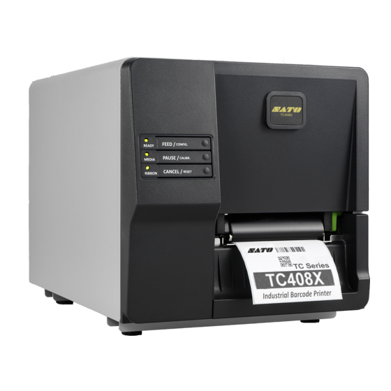
- Page 1 TC Series User's Manual TC408 TC408X...
- Page 2 SATO CORPORATION http://www.satoworldwide.com TC Series - User’s Manual...
-
Page 3: Table Of Contents
Table of Contents 1. Introduction ................ 6 Proprietary Statement ............6 Product Improvements ............6 Liability Disclaimer ..............6 Document Icons ..............7 2. Getting Started ..............8 Unpacking Printer ..............8 Package Contents ............... 9 Printer Overview ..............10 Front View: ............... - Page 4 4. Communications ..............37 Interfaces and Requirements ..........37 USB Interface Requirements ..........37 Serial (RS-232) Interface Requirements ......38 Parallel Interface Requirements ........38 Serial and Parallel Cabling Requirements......38 Communicating with Printer ..........39 Installing a Plug and Play printer driver (for USB only) ..39 Installing a Printer Driver (for other interfaces except USB) ..................46 5.
- Page 5 7. Index ................. 73 Rotary Cutter and Guillotine Cutter Installation ....73 Rotary Cutter and Guillotine Cutter Settings ......76 Rotary Cutter with Paper Jam ..........79 Guillotine Cutter with Paper Jam .......... 80 TC Series - User’s Manual...
-
Page 6: Introduction
SATO CORPORATION has been advised of the possibility of such damages. -
Page 7: Document Icons
Document Icons The following icons indicate useful and important information as described: Note: gives additional and important information. A note also provides information that may only be applicable to some situations. Caution: Advises of possible failure to take or avoid a specific action under certain circumstances. -
Page 8: Getting Started
2. Getting Started Thank you for choosing TC Series printer, which is ideally designed to easily bring more efficiency for your business. This manual will help you get to know your new printer and provide sufficient information needed. Unpacking Printer After receiving your printer, please unpack and check first before use: 1. -
Page 9: Package Contents
Package Contents Printer Quick Installation Guide Power Cord USB Cable Ribbon Core Adaptors Ribbon 1” ID Core for Quick Installation Guide CD (Documentation & Software) Power Cord Printer USB cable Ribbon Core Adaptors 1”... -
Page 10: Printer Overview
Printer Overview Front View: Top Access Door Front Panel Front Cover Printer’s front panel includes: 3 LED indicators (READY, MEDIA and RIBBON) 3 buttons (FEED, PAUSE and CANCEL) TC Series - User’s Manual... -
Page 11: Rear View
Rear View: Parallel Port USB Port RS232 Serial Port Power Switch AC Power connector TC Series - User’s Manual... -
Page 12: Interior View I
Interior View I Media Supply Guide DIP Switch Media Supply Hanger Ribbon Pick-up Holder Head Latch TC Series - User’s Manual... -
Page 13: Interior View Ii
Interior View II Print Head Media Shaft Ribbon Supply Holder Media Guide Head open Transmissive Sensor Switch Platen Roller Reflective Sensor Tear Bar / Front Cover TC Series - User’s Manual... -
Page 14: Connecting Power Cord
Connecting Power Cord Caution: Do not operate in an area where the printer might get wet. Refer to the steps below: 1. First turn Power switch to the “O” position. Make sure to turn off printer’s power first, every time before connecting or disconnecting Power cord from printer. -
Page 15: Loading Media
Loading Media Preparing Media Note: The inside wound or outside wound media rolls can be loaded into the printer in the same way. In case media roll may become dirty or dusty during shipment, handling, or storage, firstly remove the outside length of media, which helps to avoid dragging adhesive or dirty media between the print head and platen roller. - Page 16 2. Find the Central point of Media supply hanger first, represented by scale “0”. Centrally place media roll to align with central point of Media supply hanger, and then check the scale numbers located right upon both edges of media roll. Media supply hanger 0: Central point Then, find the Knob under Media supply guide at left, turn clockwise to...
- Page 17 3. Flip down the Media supply guide at right. Media supply guide Place and push the media roll to central point of the Media supply hanger. Check the scale number on Media Supply Hanger and make sure the roll is centrally aligned. Turn the Knob under Media supply guide at left anti-clockwise to tighten it and fix media roll’s position.
- Page 18 4. Push the Head latch to open the printer module. PUSH Head latch Pull a short length of media till it reaches the Platen roll of printer. Locate the media under Media shaft. Media shaft Platen roller TC Series - User’s Manual...
-
Page 19: Sensor Type
5. Press the lock of Media guide at right to adjust media guides’ positions to fit media’s both edges. Make sure gap or black-mark of media can pass over to be detected by Media sensor. Media guide Transmissive sensor Reflective sensor Note: Select the appropriate sensor type which is applicable to the media in use. - Page 20 6. Close the printer module and then press firmly at the both sides to properly latch until you hear a click. Note: For thermal transfer printing mode, ribbon is required to be installed. Refer the steps in section: “Loading Ribbon” Press the FEED button to feed labels out of the printer.
- Page 21 7. To tear media, pull the media edge against the Tear-off bar as in the direction below: Tear-off bar Tear Direction Note: If printer will be printed in thermal transfer mode, which requires ribbon to be installed, continue the next section, “Loading Ribbon”.
-
Page 22: Loading Ribbon
Loading Ribbon The following steps only apply to thermal transfer printing mode only. Direct thermal does not need ribbon to be installed. Note: 1. Media and ribbon types should be matched to provide with optimal print results. 2. Always use ribbon that is wider than the media to protect the print head from wear. -
Page 23: Placing Ribbon Rolls
Placing Ribbon Rolls 1. Open Top access door of the printer. Top access door 2. Push the Head latch to open the printer module. PUSH Head latch TC Series - User’s Manual... - Page 24 3. Lift up the printer module to check the Ribbon supply holder. Ribbon supply holder TC Series - User’s Manual...
- Page 25 4. Install one ribbon roll and rotate it until the notches align and lock into the left side of Ribbon supply holder, and then into the right. Note: The Ribbon Supply Holder accepts the coated side of ribbon to be wound ink-side IN or wound ink-side OUT. TC Series - User’s Manual...
- Page 26 5. Install the other ribbon roll and rotate it until the notches align and lock into the left side of Ribbon pick-up holder, and then the right. Ribbon pick-up holder Pull a short length of ribbon from Ribbon supply holder. Move upward and attach to Core for ribbon on Ribbon pick-up holder.
- Page 27 6. Close the printer module, and then press firmly at both sides to properly latch it until you hear a click. Rotate Thumb wheel of Ribbon pick-up holder to remove slack and ribbon wrinkle, and to align ribbon on the spindles. Thumb wheel TC Series - User’s Manual...
- Page 28 7. Double-check the installation path of media and ribbon: TC Series - User’s Manual...
-
Page 29: Printer Operations
3. Printer Operations LED Indicators There are three LED indicators on printer’s front panel - READY, MEDIA and RIBBON. These indicators display operation status of the printer to help users’ comprehension for further actions to take. READY On – Normal operation. Blinking –... -
Page 30: Buttons
Buttons There are three buttons. Each button carries with two basic functions. Function 2 Button Function 1 (Press the button and (Press the button) power on printer at the same time) Feed a label. FEED Perform self test & print a configuration report. -
Page 31: Media Calibration
Media Calibration Note: 1. After the media is loaded, please perform media calibration to calibrate the label sensor before printing. Also perform media calibration every time after changing media types. 2. Before calibration, be sure media and ribbon (for thermal transfer printing) have been loaded correctly. -
Page 32: Printing A Configuration Report
4. Printer will enter Dump mode after printing configuration, if it’s with SATO SEPL emulation. To return to normal operation mode from Dump mode, press the CANCEL/RESET button. Another way is to turn off printer power, and then restart printer. - Page 33 Sample of Configuration Report – based on TC408: TC Series - User’s Manual...
- Page 34 Sample of Configuration Report – based on TC408X: TC Series - User’s Manual...
-
Page 35: Dip Switch
DIP Switch DIP Switch settings indicated on printer’s configuration report are set practically by DIP Switch on main board, located near Media supply hanger. As described below, some of the DIP switches can be adjusted upward or downward, representing different functions. Note: Turn off the printer before setting DIP Switch. -
Page 36: Resetting To Factory Default Settings
Resetting to Factory Default Settings To reset the printer to factory default settings: 1. Turn off the printer. 2. Press and hold the CANCEL/RESET button and turn on the printer. 3. When RIBBON indicator start to blink, release the CANCEL/RESET button. 4. -
Page 37: Communications
4. Communications Interfaces and Requirements SATO TC printer series come with a nine-pin Electronics Industries Association (EIA) RS-232 serial data interface, a USB interface, and Centronics Parallel. A variety of interface options are suitable for versatile applications: Note: 1. Please be sure to plug the power cord into the power connector on the back of printer before connecting communication cables. -
Page 38: Serial (Rs-232) Interface Requirements
Serial (RS-232) Interface Requirements The required cable must have a nine-pin "D" type male connector on one end, which is plugged into the mating serial port located on the back of the printer. The other end of the signal interface cable connects to a serial port on the host computer. -
Page 39: Communicating With Printer
Communicating with Printer Seagull driver SATO provides with printer can be applied to all applications under Windows XP/ Vista/ Windows 7/ Windows 8, supporting 32-bit/ 64-bit operation systems. With this driver you can operate any popular Windows software applications including SATO Bartender UL label editing software or MS Word, etc., to print to this... - Page 40 Steps: 1. Turn off the printer. Plug the power cord into the power outlet, and then connect the other end of the cord to printer's power connector. Connect a USB cable to the USB port on printer and also on your computer. 2.
- Page 41 4. On the prompt, Windows Printer Driver, select “I accept…” and click "Next": Assign the directory to keep Seagull driver, (for example: C:\Seagull) and click "Next": TC Series - User’s Manual...
- Page 42 5. Make sure the first option ”Run Driver Wizard…” is checked, and click "Finish": Select “Install printer drivers” and click "Next": TC Series - User’s Manual...
- Page 43 6. This Seagull Driver Wizard prompt will pop up, if printer is off: If USB cable is well-connected to PC and to printer, and printer is powered on, this Seagull Driver Wizard prompt will pop up. Select the first radio button to “Install a driver for a Plug and Play printer”: Then click “Next”.
- Page 44 7. Enter Printer name (i.e. SATO TC408X SZPL) and select "do not share this printer”, and click "Next": Check the data on the screen shown. If all is correct, click "Finish": TC Series - User’s Manual...
- Page 45 8. After the related files have been copied to your system, click "Finish": After driver installation is complete, click "Close". Now the driver should have been installed completely. TC Series - User’s Manual...
-
Page 46: Installing A Printer Driver (For Other Interfaces Except Usb)
Installing a Printer Driver (for other interfaces except USB) Steps: 1. Turn off the printer. Plug the power cord into the power outlet, and then connect the other end of the cord to printer's power connector. Connect the Parallel cable or Serial cable to the proper port on the printer and also on your computer. - Page 47 3. On the prompt, Windows Printer Driver, select “I accept…” and click "Next": Assign the directory to keep Seagull driver, (for example: C:\Seagull) and click "Next": TC Series - User’s Manual...
- Page 48 4. Check the first option “Run Driver Wizard…” and click "Finish": Select “Install printer drivers” and click "Next": TC Series - User’s Manual...
- Page 49 5. This Seagull Driver Wizard prompt will pop up: 6. Select model & emulation and click “Next”. The following examples are based on model TC408X SZPL: TC Series - User’s Manual...
- Page 50 7. Select the port of the printer and click "Next": 8. Enter Printer name (i.e. SATO TC408X SZPL) and select "do not share this printer”, and click "Next": TC Series - User’s Manual...
- Page 51 Check the data on the screen shown. If all is correct, click "Finish": After the related files have been copied to your system, click "Finish": TC Series - User’s Manual...
- Page 52 10. After driver installation is complete, click "Close". Now the driver should have been installed completely. TC Series - User’s Manual...
-
Page 53: Troubleshooting
5. Troubleshooting LED Diagnosis Normally, if the printer is in not working properly, the "READY" LED blinks continuously, and printing and communication between the host and printer stops. Meanwhile, blinking LEDs indicate a problem. Check the LEDs and refer to the following solutions suggested below. Media Problems Indication READY and MEDIA LEDs... - Page 54 Ribbon Problems Indication READY and RIBBON LEDs Blinking Possible Problems Solutions Remarks Ribbon out Supply the ribbon roll Not applicable to direct thermal. Ribbon jam Recover the jam Ribbon sensor error Replace ribbon sensor Note: If you use direct thermal, set by labeling software, windows driver, printer commands, or Switch.
- Page 55 Check the media. Cutter failed Check the connection between cutter and main board. Call for service. Memory full Check graphics and soft fonts Need to reboot the from host. Delete by system. application software for those no longer in use. Note: After a problem is solved, press CANCEL to continue printing.
-
Page 56: Printer Status
Printer Status Blinking Printer Status Description Printer is paused. Press PAUSE or CANCEL to PAUSE READY return to normal. MEDIA Media is uninstalled or used up. Load new MEDIA OUT media to the printer. READY RIBBON Ribbon is uninstalled or end-of-ribbon RIBBON OUT occurred. -
Page 57: Transmission Problems
Transmission Problems If the host shows "Printer Time out" 1. Check if the communication cable (parallel or serial) is connected securely to your parallel or serial port on the PC and to the connector on the printer at the other end. 2. -
Page 58: Printer Maintenance
Printer Maintenance Vertical streaks in the printout usually indicate a dirty or faulty print head. (Refer to the following examples.) Clean the print head. If the problem persists, replace the print head. For unstable ribbon roll rotation, check the label path and make sure the head latch is securely closed. -
Page 59: Cleaning Print Head
Cleaning Print Head To keep print Head remain in its best conditions and efficiency and to extend duration for use, regular cleaning action is needed. Caution: Warranty of print heads will be void if print head serial number is removed, altered, defected, or made illegible, under every circumstance. - Page 60 Cleaning Interval It’s strongly recommended to regularly clean print heads at least when changing every one label roll (in direct thermal printing mode) or every one ribbon roll (in thermal transfer printing mode). In addition, if printers are operated under critical applications and environments, or if it’s found that print quality is degraded, please clean print heads more frequently.
-
Page 61: Cleaning Roller
Cleaning Roller Using a cotton bud moistened with alcohol, clean the roll and remove any attached glue. Note: Clean the roller after it has been in contact with foreign materials such as dust or adhesives. Cleaning Media Compartment Clean the media compartment with a cotton bud that has been moistened with a mild detergent. -
Page 62: Product Specification
LED indicator (Ready/Media/Ribbon) x 3 / Interface Button (Feed(Config.)/Pause(Calibr.)/Cancel(Reset)) x 3 Communication Parallel, RS-232(Baud rate: 2400~115200 bps), USB Interface TC408X: SZPL Emulation TC408: SDPL, SEPL Software - Windows Driver (Windows XP/Vista/7/8) Label editing BarTender® from Seagull Scientific Software – Printer Utility, Font Utility Utility... - Page 63 Max roll capacity(OD):8”(203mm) Core size:1”(25.4mm)/ 1.5”(38.1mm) / 3”(76.2mm) Ribbon roll – max OD: 2.6”(67mm) Ribbon Length: max 300m Core size – ID: 1”(25.4mm) Ribbon Ribbon Width: 1”~4”, Wax, Wax/Resin, Resin (Ribbon wound ink-side out or ink-side in) Dimensions W 282.7mm x H 285.4mm x L 466.6mm Weight 9 kg Internal Universal Switching Power supply...
-
Page 64: Fonts, Barcodes, And Graphics Specification
Fonts, Barcodes, and Graphics Specification The specifications of fonts, bar codes and graphics depends on the printer emulation. The emulations SDPL, SEPL, and SZPL are printer programming languages, through which the host can communicate with your printer. Printer Programming Language SDPL Programming SDPL Language... -
Page 65: Printer Programming Language Sepl
checksum/ with human readable check digit/ with modulo 10 checksum & shipping bearer bars) 、 GS1 Data bar (RSS) MaxiCode、PDF417、Data Matrix (ECC 200 only) 、 2D Barcodes QR code、Composite Codes、Aztec Barcode、 Micro PDF417 Printer Programming Language SEPL Programming SEPL Language Internal fonts 5 fonts with different point size 8 bits code page : 437, 850, 852, 860, 863, 865, 857,... -
Page 66: Printer Programming Language Szpl
Code 39、UPC-A、UPC-E、Matrix 2 of 5、 UPC-Interleaved 2 of 5、 Code 39 with check sum digit 、Code 93、EAN-13、 EAN-8 (Standard, 2 /5digit add-on) 、Codabar、 Postnet、Code128 subset A/B/C、 Code 128 UCC (shipping container code) 、 1D Barcodes Code 128 auto、UCC/EAN code 128 (GS1-128) 、 Interleave 2 of 5、Interleaved 2 of 5 with check sum、... - Page 67 GRF, Hex and GDI Graphics (BMP files can be converted to GRF file by Printer Utility) Code39、UPC-A、UPC-E、Postnet、 Code128 subset A/B/C、Interleave 2 of 5、 Interleaved 2 of 5 with check sum、 Interleaved 2 of 5 with human readable check digit、 1D Barcodes Code 93、Code 39 with check sum digit、...
-
Page 68: Interface Specification
Interface Specification This section presents the interface specifications of IO ports for the printer. These include pin assignments, protocols and detailed information about how to properly interface your printer with your host or terminal. USB Interface Connector Terminal Pin Assignment Signal Description VBUS... -
Page 69: Serial Interface
Serial Interface The RS232 connector on the printer side is a female, DB-9. Signal Description No function Shorted to Pin - 6 Received Data, RxD Input. Serial “Received Data” Transmitted Data, TxD Output. Serial “Transmitted Data”. No function No connection Signal Ground No function Shorted to Pin - 1... -
Page 70: Parallel (Centronics) Interface
Parallel (Centronics) Interface The parallel port is a standard 36-pin Centronics, which complies with IEEE 1284 standard (compatibility mode). Pin assignments are as follows: Direction Definition Direction Definition n/STROBE Ground Data 1~8 Ground nACK BUSY 19~30 Ground nFAULT 33~35 Auto Polling Both the serial port and parallel port of this printer can be activated at the same time, i.e the printer can simultaneously communicate with two PCs via different ports. -
Page 71: Connection With Host
Connection with Host Host 25S Printer 9P Host 9S Printer 9P (PC or compatible) (PC or compatible) DTR 20 …… 1 DSR DTR 4 …… 1 DSR DSR 6 …… 6 DTR DSR 6 …… 6 DTR TX 2 …… 2 RX TX 3 ……... - Page 72 The simplest way to connect to other hosts (not PC compatible) or terminals is: Printer Terminal/Host Pin 2- RxData ……… TxData Pin 3- TxData ……… RxData Pin 5- Ground ……… Ground In general, as long as the data quantity is not too large and you use Xon/Xoff as flow control, it will be problem free.
-
Page 73: Index
7. Index Rotary Cutter and Guillotine Cutter Installation Caution: Blades inside cutters are quite sharp. To ensure your safety, never attempt to insert fingers or objects into rotary cutter or guillotine cutter. During all cutter operations including installation, adjustment, or recovery from paper jam, please power off printer first and unplug printer’s power cord. - Page 74 2. Hold and pull Front Cover to the right, to remove it off from printer. 3. Thread Cutter Cable through the hole between print module and case. 4. Find screws in cutter‘s box. Install Cutter Module by fixing Cutter Bracket on Printer Chassis with screws at both sides. TC Series - User’s Manual...
- Page 75 5. Remove the left printer case by loosening screws. Connect Cutter Cable to connector (CUTTER) on printer main board. 6. Find Cutter Baby Board in cutter‘s box, and then install onto J16 socket on printer main board. 7. Assemble back the printer case. Now cutter installation has been completed through the steps above.
-
Page 76: Rotary Cutter And Guillotine Cutter Settings
Rotary Cutter and Guillotine Cutter Settings Before printing and cutting tasks, please make sure whether the cutter in use is Rotary Cutter, or Guillotine Cutter. Then select proper settings via Seagull Driver for printer. The following installation steps are based on TC408X as an example. - Page 77 3. “Cutter Setup” prompts will be indicated as below. Check on the radio button, “Rotary” if there’s Rotary Cutter installed. Then click “OK“: Check on the radio button, “Guillotine” if there’s Guillotine Cutter installed. Then click “OK“: TC Series - User’s Manual...
- Page 78 4. Go to “Printing Preference” prompt of TC408X driver and then click on the “Stock” tag. Check “Mode” settings and select “Cut”. ※ If there’s Guillotine Cutter installed and partial cut function is needed, select “Partial Cut” in “Mode” settings. TC Series - User’s Manual...
-
Page 79: Rotary Cutter With Paper Jam
Rotary Cutter with Paper Jam If there is paper jam inside rotary cutter, refer to Rotary Cutter Installation section to remove the rotary cutter. Check the Cam as marked in Figure 2; find a slotted screwdriver to turn counter-clockwise. During turning the Cam of cutter, release the blade from paper and them remove the paper from the cutter. -
Page 80: Guillotine Cutter With Paper Jam
Guillotine Cutter with Paper Jam If there is paper jam inside guillotine cutter, check in Figure 2 and find where the screw under guillotine cutter. It is to control cut actions of guillotine cutter. Find a Phillips screwdriver to lay down the blade by turning the screw as directions marked in the figures.
Need help?
Do you have a question about the TC408 and is the answer not in the manual?
Questions and answers