Table of Contents
Advertisement
Quick Links
Advertisement
Table of Contents

Related Manuals for HIKVISION DS-C12A

Summary of Contents for HIKVISION DS-C12A
- Page 1 Video Wall Controller User Manual...
- Page 2 WITHOUT LIMITATION, MERCHANTABILITY, SATISFACTORY QUALITY, OR FITNESS FOR A PARTICULAR PURPOSE. THE USE OF THE PRODUCT BY YOU IS AT YOUR OWN RISK. IN NO EVENT WILL HIKVISION BE LIABLE TO YOU FOR ANY SPECIAL, CONSEQUENTIAL, INCIDENTAL, OR INDIRECT DAMAGES,...
- Page 3 Video Wall Controller User Manual INFRINGE ON THE RIGHTS OF THIRD PARTIES, INCLUDING WITHOUT LIMITATION, RIGHTS OF PUBLICITY, INTELLECTUAL PROPERTY RIGHTS, OR DATA PROTECTION AND OTHER PRIVACY RIGHTS. YOU SHALL NOT USE THIS PRODUCT FOR ANY PROHIBITED END-USES, INCLUDING THE DEVELOPMENT OR PRODUCTION OF WEAPONS OF MASS DESTRUCTION, THE DEVELOPMENT OR PRODUCTION OF CHEMICAL OR BIOLOGICAL WEAPONS, ANY ACTIVITIES IN THE CONTEXT RELATED TO ANY NUCLEAR EXPLOSIVE OR UNSAFE NUCLEAR FUEL-CYCLE, OR IN SUPPORT OF HUMAN...
- Page 4 Video Wall Controller User Manual Regulatory Information FCC Information Please take attention that changes or modification not expressly approved by the party responsible for compliance could void the user's authority to operate the equipment. FCC compliance: This equipment has been tested and found to comply with the limits for a Class B digital device,pursuant to part 15 of the FCC Rules.
- Page 5 Video Wall Controller User Manual standards listed under the EMC Directive 2014/30/EU, the RoHS Directive 2011/65/EU. 2012/19/EU (WEEE directive): Products marked with this symbol cannot be disposed of as unsorted municipal waste in the European Union. For proper recycling, return this product to your local supplier upon the purchase of equivalent new equipment, or dispose of it at designated collection points.
- Page 6 Video Wall Controller User Manual Preface Applicable Model This manual is applicable to video wall controllers. About the Default This device has the following defaults: Parameter Default Value User name admin IP address 192.0.0.64 Symbol Conventions The symbols that may be found in this document are defined as follows. Symbol Description Indicates a hazardous situation which, if not avoided, will or could...
- Page 7 Video Wall Controller User Manual • CAUTION: Risk of explosion if the battery is replaced by an incorrect type. • Improper replacement of the battery with an incorrect type may defeat a safeguard (for example, in the case of some lithium battery types). •...
-
Page 8: Table Of Contents
Video Wall Controller User Manual Contents Chapter 1 Product Introduction ....................1 1.1 Overview ..........................1 1.2 Key Feature ..........................1 1.3 Packing List ..........................1 1.4 Device Appearance ........................ 2 1.4.1 Front Panel ........................2 1.4.2 Rear Panel ........................3 1.5 Client Management Software .................... - Page 9 Video Wall Controller User Manual 3.4.2 Print a Layout File ......................18 3.4.3 Import a Layout File ....................19 3.5 Configure Mirroring Display ....................19 Chapter 4 Device Installation and Cabling ................. 22 4.1 Install Your Devices ......................22 4.2 Connect Cables ........................22 4.2.1 Cable Connection Requirements .................
-
Page 10: Chapter 1 Product Introduction
Video Wall Controller User Manual Chapter 1 Product Introduction 1.1 Overview The video wall controller is a pure hardware image processing device based on Field Programmable Gate Array (FPGA), which supports 4K@60 Hz signal input and random rotation and placement of displays for achieving more creative and eye-catching display effects. -
Page 11: Device Appearance
Video Wall Controller User Manual Item Picture Quantity User manual CD-ROM 1.4 Device Appearance Figure 1-1 Device Appearance 1.4.1 Front Panel Figure 1-2 Front Panel Table 1-2 Front Panel Interface Description Name Description Power indicator Turns steady red after power-on STAT System status indicator •... -
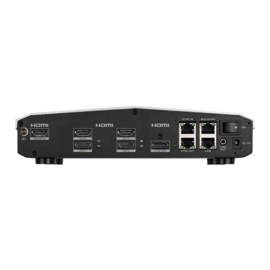
Page 12: Rear Panel
Video Wall Controller User Manual Name Description • Signals are not inputting and not displayed on the video wall: unlit • Signals are displayed on the video wall but not inputting: green • Signals are inputting but not displayed on the video wall: red •... -
Page 13: Client Management Software
Video Wall Controller User Manual Name Description HDMI LOOP OUT HDMI loop output interface for device cascading, up to 4K@60 Hz output SYNC IN Sync input interface for synchronizing signals between devices SYNC OUT Sync output interface for synchronizing signals between devices RS-232/RS485 RS232 and RS485 multiplexing port only for debugging,... -
Page 14: Operation Process
Video Wall Controller User Manual Figure 1-4 Client Management Software 1.6 Operation Process The following figure describes the basic operation process of creating an artistic video wall. Figure 1-5 Operation Process of Creating an Artistic Video Wall... -
Page 15: Chapter 2 Activate And Add Devices
Video Wall Controller User Manual Chapter 2 Activate and Add Devices 2.1 Activate Your Device For the inactive devices, you are required to create a password to activate them before they can be added to the software and work properly. Before You Start Make sure the device to be activated is connected to the network and is in the same subnet with the PC running the client. -
Page 16: Add Device By Ip Address Or Domain Name
Video Wall Controller User Manual 2.2.1 Add Device by IP Address or Domain Name If you know the IP address or domain name of the device to add, you can add devices to the client by specifying the IP address (or domain name), user name, password, etc. Steps 1. -
Page 17: Add Devices By Ip Segment
Video Wall Controller User Manual View Device Status Click on Operation column to view device status, including cameras, recording status, signal status, hardware status, etc. Edit Device Click on Operation column to edit the device information, such as Information IP address, user name, and password. Refresh Click on Operation column to get the latest device information. -
Page 18: Configure Network Parameters
Video Wall Controller User Manual Proper configuration of all passwords and other security settings is the responsibility of the installer and/or end-user. 5. Check Synchronize Time to synchronize the device time with the PC running the client after adding the device to the client. 6. -
Page 19: Chapter 3 Artistic Video Wall Configuration
Video Wall Controller User Manual Chapter 3 Artistic Video Wall Configuration This chapter describes how to design an artistic video wall solution on the client. Designing a video wall solution includes configuring monitors, configuring input signal sources, and linking devices with the video wall. -
Page 20: Configure Display Properties
Video Wall Controller User Manual 5. Optional: Set Background Color of your displays. The background color applies to all displays. 6. Click Add to Wall to add the displays to the video wall canvas on the right. 3.1.2 Configure Display Properties After adding displays to the wall, configure display properties to ensure proper displaying. - Page 21 Video Wall Controller User Manual Note Do not overlap displays when adjusting display positions. Dotted-line boxes appear around if displays are overlapped. Figure 3-2 Adjust Display Positions Table 3-2 Description of Display Position Adjustment Function Description X-Coordinate/Y- Enter the X and Y coordinates of the reference point (the junction of Coordinate the green line and the blue line), and the display will be moved to the corresponding position.
-
Page 22: Configure An Input Source
Video Wall Controller User Manual Table 3-3 Description of Precise Position Adjustment Function Description Up/ D own/ L eft/ R ight Click the arrows to move the display to the corresponding directions arrows by 1 mm at a time. Clockwise/ Click the arrows to rotate the display clockwise or anticlockwise by 0.1 Anticlockwise arrows degree at a time. - Page 23 Video Wall Controller User Manual Figure 3-4 Configure an Input Source 2. Click Create to automatically create an input source for the current video wall. 3. Select a sample source file stored on the client or on your local computer to display in the window and check the display effect.
-
Page 24: Configure A Device Topology
Video Wall Controller User Manual Figure 3-6 Replicate Mode Caution In Replicate mode, the displays are adjusted to have the same output resolution, which is consistent with that of the display connected to the HDMI OUT 1 interface. 5. Optional: Select the rotation angle to rotate the image at the corresponding angle. 0°, 90°, 180°, and 270°... -
Page 25: Change A Device Topology
Video Wall Controller User Manual 3.3.1 Change a Device Topology You can change the device topology as needed. Steps 1. Click Artistic Configuration → Device Topology . The client automatically configures a cascading topology for your devices, and you can connect physical devices according to the topology. Figure 3-7 Configure a Device Topology 2. -
Page 26: Layout Management
Video Wall Controller User Manual Steps 1. Click Artistic Configuration → Device Topology . Figure 3-8 View Topology Status 2. Check the device cascading relationship, cable connection status, and status of signal input and output interfaces. The following table describes the connection lines and indicators. Table 3-6 Description of Connection Lines and Indicators Name Color Description... -
Page 27: Save A Layout File
Video Wall Controller User Manual 3.4.1 Save a Layout File You can save a video wall layout as a file which can be used as a template to provide reference for other projects. Steps 1. Click Artistic Configuration → Display Configuration . 2. -
Page 28: Import A Layout File
Video Wall Controller User Manual 3.4.3 Import a Layout File You can import a layout file to the client for use or reference. Steps 1. Click Artistic Configuration → Display Configuration . 2. Click to open a layout file from the local computer. 3.5 Configure Mirroring Display You can create a mirroring effect on a video wall by cascading two devices. - Page 29 Video Wall Controller User Manual Figure 3-10 Configure Mirroring Mode 5. Click Artistic Configuration → Device Topology , draw a loop connection line for the two devices. Click, hold, and drag a line from the loop out interface of the first device to the loop in interface of the second device.
- Page 30 Video Wall Controller User Manual Figure 3-12 Device Topology (with Mirroring Configured) 6. After mirroring is configured, continue to finish other configurations, such as layout adjustment and device linking.
-
Page 31: Chapter 4 Device Installation And Cabling
Video Wall Controller User Manual Chapter 4 Device Installation and Cabling After finishing the design of your video wall solution on the client, you can install your devices and video wall according to the design. 4.1 Install Your Devices Install Your Video Wall Controllers Place your devices on flat surfaces such as a table, or on metal surfaces such as a video wall bracket or the rear of an LCD screen with the magnet feet on the bottom of your devices. -
Page 32: Cable Connection Description
Video Wall Controller User Manual Application Scenario Cables Required • Sync cable • Power cable Figure 4-1 Normal Signal Splicing on Video Wall Figure 4-2 Cascading Splicing of a Signal 4.2.2 Cable Connection Description See the following table for details about how to connect cables. - Page 33 Video Wall Controller User Manual Note All cables mentioned in the following table require you to purchase separately. Table 4-2 Cable Connection Description Cable Connection Method Grounding cable 1. Use a Phillips screwdriver to remove the grounding screw on your device. 2.
- Page 34 Video Wall Controller User Manual Cable Connection Method Serial cable Note The serial port is used for debugging only. 1. Determine the serial cable order of the serial interface of your devices. The RS-232/485 serial interface of the device is an RJ45 type with eight feet, and feet 2 and 3 correspond to RX and TX of an RS-232 interface, and feet 4 and 5 correspond to RS-485+ and RS-485- of an RS-485 interface.
-
Page 35: Chapter 5 Device Configuration And Maintenance
Video Wall Controller User Manual Chapter 5 Device Configuration and Maintenance You can perform device configuration and maintenance operations on the client, such as configuring device time and security services, changing the device password, searching and backing up operation logs, remotely restarting or upgrading devices, and restoring factory default settings. -
Page 36: Reset Device Password
Video Wall Controller User Manual 5. Click Save. 6. Optional: To manually synchronize time, click Synchronization. 5.3 Reset Device Password If you forget your device password, just reset your password by exporting and importing a GUID file. Steps 1. Click Maintenance and Management → Device Management , and select the desired device from the online device list and click Reset Password. -
Page 37: View Device Information
Video Wall Controller User Manual 5.4 View Device Information You can view device information such as the device type, serial No., or version No. on the client. Steps 1. Click Maintenance and Management → Device Management , select the desired device in the list and click Remote Configuration on the Operation column. -
Page 38: Configure Security Parameters
Video Wall Controller User Manual 5.6 Configure Security Parameters Configure security parameters as needed. Steps 1. Click Maintenance and Management → Device Management , select the desired device in the list and click Remote Configuration on the Operation column. 2. Click System → Security . 3. -
Page 39: Restore Default Parameters
Video Wall Controller User Manual 2. Click System → Log Query . 3. Set the Search Mode. Major Type, Minor Type, Start Time, and End Time are available. 4. Click Search to search logs. Click Backup to back up the logs as needed. 5.9 Restore Default Parameters You can restore your device to factory default settings as needed, for example, when your device encounters a fault that is difficult to resolve. -
Page 40: Chapter 6 User Management
Video Wall Controller User Manual Chapter 6 User Management The device has only one admin user. You can change the password on the client. Before You Start Steps 1. Click Maintenance and Management → Account Management . 2. Click Change Password. 3. -
Page 41: Chapter 7 Operation And Maintenance
Video Wall Controller User Manual Chapter 7 Operation and Maintenance You can perform maintaining operations in the menu to ensure a smooth and convenient usage of the client. Click in the upper-right corner, and then click System/Tool to perform the following operations. Import/Export Configuration File You can import configuration files from local PC to the client if needed, and vice versa. -
Page 42: Chapter 8 Get More Information
Video Wall Controller User Manual Chapter 8 Get More Information Scan the following QR code to get more information about the operation and maintenance. - Page 43 UD18424B...
Need help?
Do you have a question about the DS-C12A and is the answer not in the manual?
Questions and answers