Advertisement
Quick Links
RSⅢ Installation Instructions
PRIME
●
(
)
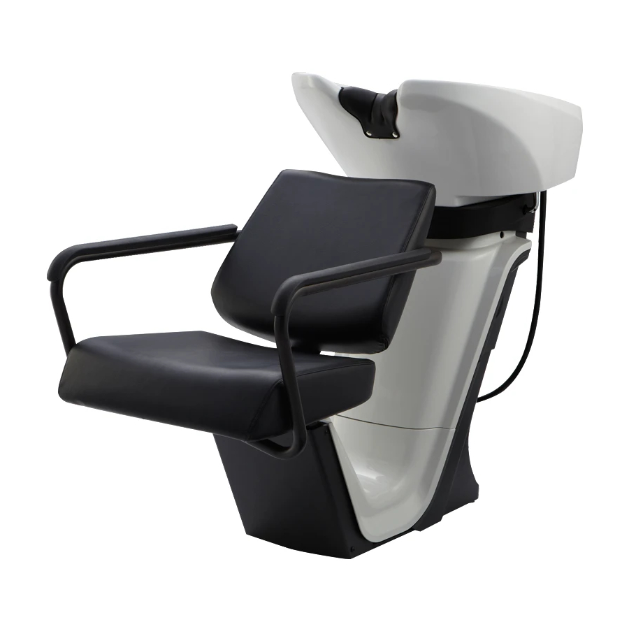
Image is of
AY-S195X
AY-P069X
LUXIS
●
(
)
Image is of
AY-LUX
AY-P069X
ELITE
●
(
)
Image is of
AY-ELI
AY-P075X
AXIS
●
PRIMO
●
COMFORT
●
LITE
●
1
Contents
Before installation
Usage conditions
Content of packaging
Carrying the main body
1.Installation of Shampoo Unit
2.Piping
3.Attach the seat
<AXIS・PRIMO・LITE・PRIME・LUXIS>
<COMFORT>
<ELITE>
4.Attach cover
Dimensions
After installation
Unit fixing position and Plumbing Layout
MEMO
To the installer
• The instructions should be thoroughly read
and understood before installation to ensure
that RSⅢ is installed correctly.
•
After installation, give these instructions to the customer.
To the customers
• Customers must ask proffessional to install RSⅢ.
• Customers must not install RSⅢ by themselves.
• Customers must store these instructions in
a safe place so as not to lose them.
* The actual shape of RSⅢ and the images and
dimensions listed in these instructions may be modified
and are subject to change without notice.
The precautions listed here are to ensure that RSⅢ
can be installed safely, and to prevent any
danger or risk to the person installing RSⅢ
or those around them. All of these precautions are
important for safety. Takara Belmont is not responsible
for any damage or risk to the person installing RSⅢ
or those around them due to accidents if
RSⅢ is installed without adhering to the precautions.
Caution
If RSⅢ is installed after ignoring this symbol,
"there is the risk of light or moderate injury or physical
damage".
Note : Plumbing should be performed by a qualified
technician and should meet all national and local
plumbing codes and ordinances. It is the responsibility
of purchaser and/or plumber to conform to national
and local codes and ordinances. Takara Belmont does
not take any responsibility or liability for plumbing and
installation.
Version 4
2
3
4
6
7
9
14
14
15
16
16
17
24
26
27
Feb 2016
Advertisement

Related Manuals for Takara Belmont RS III PRIME


Summary of Contents for Takara Belmont RS III PRIME
- Page 1 RSⅢ or those around them. All of these precautions are important for safety. Takara Belmont is not responsible for any damage or risk to the person installing RSⅢ ELITE...
- Page 2 Before installation Installation of pipes The following are important points to adhere during the installation of pipes. Read through the details carefully and ensure that the pipes are installed correctly. When installing this product, ensure that installation of pipes adheres to the instructions outlined in "Precautions during installation of pipes".
- Page 3 Pipe risers Hot water / water supply Rc 1/2"; pipe risers from floor; rise dimensions: hot water 60 mm; water 60 mm Drainage VU40/VP40; pipe risers from floor; rise dimensions: 100 mm Changing the pipe form RS1 The pipe risers for hot water and the water supply and drainage for RS1 can be used without changing the pipe. Hot water / water supply Rc 1/2";...
- Page 4 Content of packaging Shampoo Unit Side □Shampoo Unit □Lower-front Chair Cover □Neck cushion □Flexible pipe(2) (※) Lower Chair Cover Maintenance Cover □Drain cap □Hair catcher □Water stop valve(2) □Drain hose packing (※) (※) (L=200mm) □Pipe packing □Drain hose clamp □Hexagonal Wrench □Trickle stopper rubbes □Wrench (※)...
- Page 5 Step <AXIS・PRIMO・LITE> Double-Step U-shaped Step ・Step Fixing Screws M8 x 30 hexagonal head bolt (with spring washer) 4 pcs. Chair Side Sheet Set <COMFORT> <COMFORT> (The illustration shows SU-COL.) Chair Main Unit (COMFORT) (The illustration shows SC-COL.) Backrest Sheet ・Chair Fixing Screws M8 x 70 Hexagonal head bolt (with plain washer/spring washer) 4 pcs.
- Page 6 Carrying the main body ■Carrying in the Shampoo Unit Lower Chair Cover (secure with tape) 1 Detach the lower chair cover and the maintenance cover from the shampoo unit. Shampoo Unit Caution Place the detached covers in a safe area. 2...
- Page 7 Installation of Shampoo Unit 1 1 Marking the bolt anchor points Paper Template (1) Set the dedicated paper template on the floor, and align it with the water, hot water, and drainage pipe risers. (2) Mark the bolt anchor position of the basin main unit. (3) Drill holes at the bolt anchor position of the basin main unit.
- Page 8 4 Installing the Lower Chair Cover (1) Set the lower chair cover so that the claw of the cover will hang on the tentatively fixed truss-head screw (M5 x 12). Claw (2) Secure the cover with the truss-head tapping screws (3) Fully tighten the truss-head screws (two locations).
- Page 9 Piping 2 <excluding AY-P073X,AY-074X> Installing the Flexible Pipe Before connecting the pipes, remove any waste from the pipes, such as dust, dirt, sand, or oil. Connect the water shutoff valve to the hot water/water supply pipes. Then, apply the furnished packing to the Flexible pipe flexible pipe and connect the pipe to the water shutoff valve.
- Page 10 3 Test water flow (1) Is there no water leaking from the pipe joints? The pipe joints may come loose during transportation, Caution so check the joints within the basin thoroughly. (2) Are the hot water supply and water supply pressures Always test the water flow to prevent at the same, stable pressure? accidents during use.
- Page 11 <AY-P073X,AY-074X> 1. Attach the vacuum breaker 1) Preassembled Vacuum Breaker, Vacuum Breaker Rubber Gasket, Hose Receiver Cap and pipe nipples with the short pipe installed in line with Vacuum Breaker the arrow that points down on the vacuum breaker body. Vacuum Breaker Rubber Gasket Hose...
- Page 12 4. Connect the hose and valves as below Cut the plug and hide the hole, and run the pipes into the cover. Connecting faucet, flow regulator, braid hose and checkvalves with water and hot water lines as shown. (VACCUME BREAKER TABLE) Marble Products Model 1729 Marble Products Model 1735 Regular Vacuum Breaker...
- Page 13 5. Attach drain hose to drain pipe Attach the drain hose using a hose clamp and apply silicon sealant as require around fitting for a water seal. Check carefully for any leaks prior to putting the until into use. Note : In case of installing the hair trap, Please follow the instruction included with the hair trap.
- Page 14 Attach the seat 3 <AXIS・PRIMO・LITE・PRIME・LUXIS> <AXIS・PRIMO・LITE・PRIME・LUXIS> Installing the Seat on the Shampoo Unit (Common) (1) Place the chair on the shampoo unit by aligning the center of the mounting pipes (four pieces) at the back of the chair and the center of the slotted hole of the chair mounting fixture of the shampoo unit.
- Page 15 <COMFORT> <COMFORT> 1 Mounting the Backrest and Armrest Pad (1) Mount the backrest with pan-head machine screws (three locations). (2) Mount the armrest pad with truss-head screws (four locations). Screws to be used (supplied with the seat set): Pan-head machine screw (M6 x 25) Truss-head screw (M5 x 30) 2 Mounting of the Chair to the Shampoo Unit See Section [1] on page 11.
- Page 16 <ELITE> <ELITE> 1 Mounting the Armrest Pad Mount the armrest pad with truss-head screws (four locations). Screws to be used (supplied with the seat set): Truss-head screw (M5 x 30) 2 Mounting of the Chair to the Shampoo Unit See Section [1] on page 13.
- Page 17 Dimensions (Unit:mm) AXIS Basin Operation Angle (for Basin Tilt Specification) (0°) Center of Drainage Pipe Seat Slide Width (150 mm, Max.) 1193 + (U-Step Specification) 1375 (Double-step Specification) 1517 Note: - The dimensions in parentheses show the dimensions when the basin is tilted forward (only for the lock-tilt specification). ※1:...
- Page 18 PRIMO Basin Operation Angle (for Basin Tilt Specification) (0°) Center of Drainage Pipe + Seat Slide Width (150 mm, Max.) 1193 (Retracted leg rest) 1253 (Leg Rest Specification) 1545 Note: - The dimensions in parentheses show the dimensions when the basin is tilted forward (only for the lock-tilt specification). - The product dimensions of the U-step and double-step specification are same as RS AXIS (Dwg.
- Page 19 COMFORT Basin Operation Angle (for Basin Tilt Specification) (0°) Center of Drainage Pipe + Seat Slide Width (150 mm, Max.) 1660 Note: - The dimensions in parentheses show the dimensions when the basin is tilted forward (only for the Lock Tilt Specification). ※1:...
- Page 20 LITE Basin Operation Angle (0°) Center of Drainage Pipe 1283 1483(U-step Specification) (Double-step Specification) 1625 Note: - The dimensions in parentheses show the dimensions when the basin operation angle is 0 degrees. ※1:Double-step Specification ※2:U-step Specification (The drawing shows AY-LI / AY-RS3-2)
- Page 21 PRIME Basin Operation Angle (0°) Center of Drainage Pipe 1254 Note: -The dimensions in parentheses show the dimensions when the basin operation is 0 degrees. (The drawing shows AY-S195X / AY-P069X)
- Page 22 LUXIS Basin Operation Angle (0°) Center of Drainage Pipe 1195 Note: -The dimensions in parentheses show the dimensions when the basin operation is 0 degrees. (The drawing shows AY-LUXIS / AY-P069X)
- Page 23 ELITE Basin Operation Angle (0°) Center of Drainage Pipe 1740 Note: -The dimensions in parentheses show the dimensions when the basin operation is 0 degrees. (The drawing shows AY-ELI / AY-P069X)
- Page 24 After installation ●Inspection Inspect the following items. Caution Be sure to execute the inspection without fail to prevent accidents during operation. (1) Check that there are no missing screws or other parts. (2) Check that there are no loose parts on the shampoo unit or the chair.If any part of the shampoo unit or the chair is loose, check the bolts at the joints again.
- Page 25 ●Installing the Lumbar Cover Slide the seat, pull the lumbar part forward, and lock it firmly to ensure easy installation. Overlay the lumbar cover. Place the lumbar cover with the cutout side B ① facing down, and align the cover and the corner Align the corners.
- Page 26 Unit fixing position and Plumbing Layout [ Unit : mm]...
- Page 27 MEMO...
- Page 28 NOTE TAKARA BELMONT CORPORATION 1-1, 2-Chome, Higashi-shinsaibashi,Chuo-ku,Osaka,Japan TEL : (06) 6213-5945 FAX : (06) 6212-3680 Printed in Japan 1E02VYA0...
Need help?
Do you have a question about the RS III PRIME and is the answer not in the manual?
Questions and answers