Table of Contents
Advertisement
Advertisement
Table of Contents

Related Manuals for Bresser MeteoTemp WTM Colour


Summary of Contents for Bresser MeteoTemp WTM Colour
- Page 1 Weather Station MeteoTemp WTM Colour Quickstart guide...
- Page 2 Visit our website via the following QR Code or web link to find further information on this product or the available translations of these instructions. www.bresser.de/P7007510 WARRANTY www.bresser.de/warranty_terms...
-
Page 3: Table Of Contents
Contents Imprint ................. 22 About this Instruction Manual........... 23 General safety instructions ..........23 Parts overview and scope of delivery ......27 Screen display ..............29 Setting up power supply............ 30 Automatic time setting............31 Receiving measurements automatically ......32 10 Key functions.............. -
Page 4: Imprint
Errors excepted. Subject to technical modifications. © 2020 Bresser GmbH All rights reserved. Reproduction of this document, including extracts, in any form (photocopied, printed etc.) or the use and distribution of this document by electronic means (image file, website etc.) is not permitted without the prior written consent of the... -
Page 5: About This Instruction Manual
Manual description: Quickstart_7007510_MeteoTemp-WTM-Colour_US_en _BRESSER_v062020a.pdf With any service inquiries, please state these information. 3 About this Instruction Manual NOTICE This Quick Start guide is not intended to replace the more detailed user manual. Please read the safety instructions and the operating in- structions carefully before use. - Page 6 • Position your device so that it can be disconnected from the power supply at any time. The power socket should be installed near the device and should be eas- ily accessible as the mains cable plug is used to dis- connect the device from the power supply.
- Page 7 • Do not expose the device to high temperatures. Use only the supplied power supply or the recommended batteries. Do not short-circuit the device or batteries or throw them into a fire! Excessive heat or improper handling could trigger a short circuit, a fire, or an explo- sion.
- Page 8 NOTICE Risk of voltage damage! The manufacturer is not liable for voltage damage due to improperly inserted batteries or through the use of an im- proper power adapter! 8/20...
-
Page 9: Parts Overview And Scope Of Delivery
5 Parts overview and scope of delivery Illustration 1: Parts overview for base station (top) and remote sensor (bottom) 9/20... - Page 10 SNOOZE/LIGHT button Display (snooze function and tempor- ary background lighting) MODE button (time mode UP button (Value setting up- selection and settings) wards) DOWN button (Value setting ALARM button (Alarm set- downwards, temperature unit ting) selection (°C/°F), pressure value selection CH button (channel selec- WAVE button (Initiate data tion)
-
Page 11: Screen Display
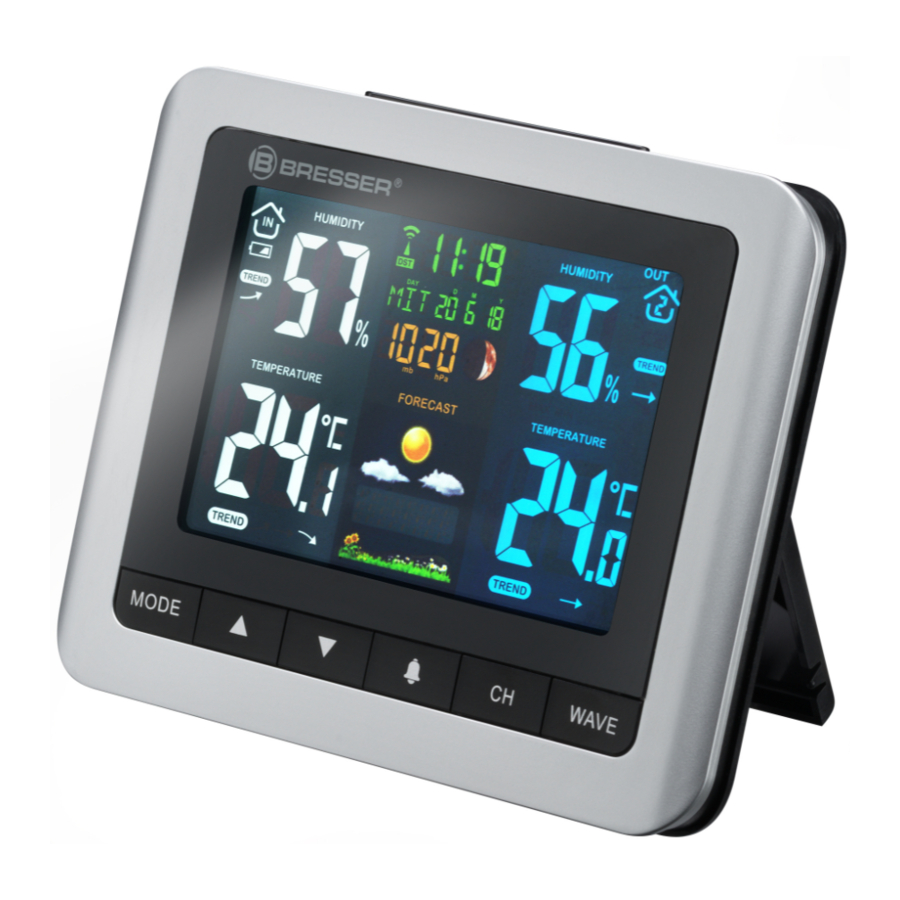
3 pcs. Mignon batteries (1.5V, AA type), 2 pcs. Micro batter- ies (1.5V, AAA type) 6 Screen display Illustration 2: Screen display for the base station Humidity trend (indoor) Battery level indicator (base (rising, steady or falling) station) Symbol indoor area Indoor humidity value Daylight saving time (DST) Symbol for radio signal... -
Page 12: Setting Up Power Supply
Humidity value (outdoor) Symbol outdoor area with channel display Remote sensor signal Symbol for channel rotation strength Battery level indicator (Re- Humidity trend (outdoor) mote sensor) (rising, steady or falling) Symbol for highest (MAX) or Moon phase lowest (MIN) value (outdoor) Air pressure (mb/hPa or Temperature value (outdoor) inHg) -
Page 13: Automatic Time Setting
Replace the battery compartment cover. Wait until the indoor temperature is displayed on the base station. NOTICE! When switching from mains power supply to battery power supply or vice versa, the power supply is being disabled for a short moment for technical reasons. -
Page 14: Receiving Measurements Automatically
8 Receiving measurements automatically Once the power supply is enabled, the base station will dis- play the measurement readings. Readings from the remote sensor will be displayed within 3 minutes after powering it If no signal is received, go ahead with the following steps: Press and hold the CH button for 3 seconds to re-initialize RC signal receiving. - Page 15 Operation Buttons Standard press Temperature Check max/ mode format selection min record (°C/°F) hold Switch pres- Clear max/ sure mode min record (hpa/mb–inHg) Time set press Backward Forward hold fast backward fast forward Alarm set press Backward Forward hold Fast backward Fast forward Operation Buttons...
-
Page 16: Technical Data
10 Technical data Base station Batteries 3x AA, 1.5 V Maximum number of sensors 3 Temperature unit °C / °F Temperature measuring -0°C – 50°C range Humidity measuring range 20% to 90% RH Humidity resolution 1% HR Barometer measuring range 800 hPa to 1100 hPa (23.62 inHg to 32.49 inHg Time display HH:MM... -
Page 17: Ec Declaration Of Conformity
50 g (without batteries) 73g (with batteries) 11 EC Declaration of Conformity Hereby, Bresser GmbH declares that the equipment type with part number: 7007510 is in compliance with Directive: 2014/30/EU.The full text of the EU declaration of conform- ity is available at the following internet address: http:// www.bresser.de •... -
Page 18: Disposal
accordance with the instructions, may cause harmful interferenceto radio communications. However, there is no guarantee that interference will not occur in a particular installation. If this equipment does cause harmful interference to radio or television reception, which can be determined by turning the equipment off and on, the user is encouraged to try to correct the interference by one or more of the following measures: -- Reorient or relocate the receiving antenna. -
Page 19: Warranty
To benefit from an extended voluntary guarantee period as stated on the gift box, registration on our website is required. You can consult the full guarantee terms as well as informa- tion on extending the guarantee period and details of our services at www.bresser.de/warranty_terms. 19/20...
Need help?
Do you have a question about the MeteoTemp WTM Colour and is the answer not in the manual?
Questions and answers