Table of Contents
Advertisement
Available languages
Available languages
Quick Links
Advertisement
Chapters
Table of Contents

Related Manuals for Bresser MeteoTemp W - DCF RC


Summary of Contents for Bresser MeteoTemp W - DCF RC
- Page 1 Wetterstation · Weather Station · Station météo · Weerstation · Stazione meteorologica · Estación meteorológica · MeteoTemp W - DCF RC Weather station Bedienungsanleitung Istruzioni per l'uso Instruction manual Manual de instrucciones Mode d’emploi Gebruikershandleiding...
- Page 2 Desidera ricevere informazioni esaustive su questo prodotto in una lingua specifica? Venga a visitare il nostro sito Web al seguente link (codice QR Code) per conoscere le versioni disponibili. www.bresser.de/P7004210 GARANTIE · WARRANTY · GARANTÍA · GARANZIA www.bresser.de/warranty_terms RECYCLAGE (TRIMAN/FRANCE)
- Page 3 Deutsch ......English ......Français......Nederlands ....Italiano......Español ......
-
Page 4: Table Of Contents
Inhaltsverzeichnis Impressum .................... 5 Gültigkeitshinweis.................. 5 Zu dieser Anleitung .................. 6 Allgemeine Sicherheitshinweise............. 6 Teileübersicht und Lieferumfang ............ 9 Display-Anzeigen .................. 11 Vor der Inbetriebnahme ................ 12 Stromversorgung herstellen.............. 13 Automatische Zeiteinstellung............... 13 10 Manuelle Zeiteinstellung............... 14 11 Zeitzone einstellen ................. 14 12 Automatische Messwerteübertragung .......... 15 13 Wettertrend..................... 15 14 Trendpfeile .................... 16 15 Entsorgung .................... 16 16 Technische Daten ................... 17 17 Garantie .................... 18... -
Page 5: Impressum
„Service“ in dieser Dokumentation. Wir bitten um Verständ- nis, dass unaufgeforderte Rücksendungen nicht bearbeitet werden können. Irrtümer und technische Änderungen vorbehalten. © 2022 Bresser GmbH Alle Rechte vorbehalten. Die Reproduktion dieser Dokumentation – auch auszugs- weise – in irgendeiner Form (z.B. Fotokopie, Druck, etc.) so- wie die Verwendung und Verbreitung mittels elektronischer Systeme (z.B. -
Page 6: Zu Dieser Anleitung
Informationen bei Serviceanfragen stets angeben. 3 Zu dieser Anleitung HINWEIS Diese Bedienungsanleitung ist als Teil des Gerätes zu betrachten! Lesen Sie vor der Benutzung des Geräts aufmerksam die Si- cherheitshinweise und die Bedienungsanleitung. Bewahren Sie diese Bedienungsanleitung für die erneute Verwendung zu einem späteren Zeitpunkt auf. - Page 7 GEFAHR Gefahr eines Stromschlags! Dieses Gerät beinhaltet Elektronikteile, die über eine Strom- quelle (Netzteil und/oder Batterien) betrieben werden. Bei unsachgemäßer Verwendung dieses Produkts besteht die Gefahr eines Stromschlags. Ein Stromschlag kann zu schwe- ren bis tödlichen Verletzungen führen. Beachten Sie daher unbedingt die nachfolgenden Sicherheitsinformationen.
- Page 8 • Bauen Sie das Gerät nicht auseinander! Wenden Sie sich im Falle eines Defekts an Ihren Fachhändler. Er nimmt mit dem Service-Center Kontakt auf und kann das Gerät ggf. zwecks Reparatur einschicken. • Gerät nicht in Wasser tauchen! • Das Gerät keinen Stößen, Erschütterungen, Staub, dau- erhaft hohen Temperaturen oder extremer Feuchtig- keit aussetzen.
-
Page 9: Teileübersicht Und Lieferumfang
5 Teileübersicht und Lieferumfang Abb. 1: Teileübersicht für Basisstation (oben) und Funksensor (unten) Display (Basisgerät) UP-Taste (Wertänderung aufwärts) DOWN-Taste (Wertände- SYNC-Taste rung abwärts) SET-Taste (Grundeinstellun- Batteriefach gen und Wechsel zwischen Anzeige in °C oder °F) Standfuß ausklappbar Aufhängevorrichtung 9 / 96... - Page 10 Display (Sensor) Funktionsleuchte Batteriefachdeckel Aufhängevorrichtung Schieberegler für die Kanal- RESET-Knopf (alle Einstellun- wahl gen zurücksetzen) Batteriefach Lieferumfang Basisgerät (A), Funksensor (B) Außerdem erforderlich (nicht im Lieferumfang enthal- ten): 4x AAA/LR03 Batterien (je 2 Stck. für Station und Sensor) 10 / 96...
-
Page 11: Display-Anzeigen
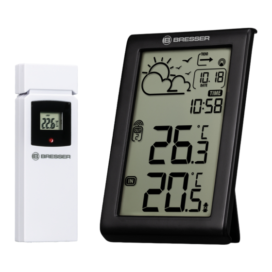
6 Display-Anzeigen Abb. 2: Display-Anzeigen für Basisstation Grafische 12-24-Stunden- Empfangssymbol Funksen- Wettertrendanzeige Symbol Temperaturbereich Automatischer Kanaldurch- Funksensor (Außentempe- lauf ratur) 11 / 96... -
Page 12: Vor Der Inbetriebnahme
Temperaturwert Funksensor Symbol Temperaturbereich (Außentemperatur) Basisstation (Innentempera- tur) Temperaturwert Basisstati- Frostwarnung on (Innentemperatur) Wettertrend-Pfeil Symbol Zeitsignal-Übertra- gung Tag und Monat Uhrzeit Symbol für Sommerzeit Batteriestandanzeige (Funk- sensor) Batteriestandanzeige (Ba- sisstation) 7 Vor der Inbetriebnahme HINWEIS Vermeidung von Verbindungsstörungen! Um Verbindungsstörungen zwischen den Geräten zu ver- meiden, sind die folgenden Punkte bei der Inbetriebnahme zu beachten. -
Page 13: Stromversorgung Herstellen
Stromverbindung getrennt werden. Werden z.B. nur die Batterien im Sensor ausgetauscht, kann das Signal anschlie- ßend gar nicht oder nicht mehr korrekt empfangen werden. Beachten Sie, dass die tatsächliche Reichweite von den je- weils verwendeten Baumaterialien der Gebäude sowie der jeweiligen Position der Basiseinheit und des Außensensors abhängt. -
Page 14: Manuelle Zeiteinstellung
Wird kein Funksignal empfangen, folgendermaßen vorge- hen: UP-Taste ca. 2 Sekunden drücken, um den Empfang des Funksignals erneut zu initiieren. Wird weiterhin kein Funksignal empfangen, muss die Zeiteinstellung manuell vorgenommen werden. 10 Manuelle Zeiteinstellung SET-Taste ca. 3 Sekunden drücken um in den Zeitein- stellungsmodus zu gelangen. -
Page 15: Automatische Messwerteübertragung
UP- oder DOWN-Taste drücken, um die gewünschte Zeitabweichung in Stunden (-12 bis +12 Stunden) zu wählen. SET-Taste abschließend ca.3 Sekunden drücken, um die eingestellte Zeitabweichung zu bestätigen. 12 Automatische Messwerteübertragung Sobald die Batterien eingelegt wurden, beginnt die Basissta- tion mit der Anzeige der Messwerte für den Innenbereich. Die ersten vom Außensensor empfangenen Messwerte wer- den innerhalb von etwa 3 Minuten nach Inbetriebnahme an- gezeigt. -
Page 16: Trendpfeile
14 Trendpfeile Steigend Stabil fallend Der Temperatur-Trendindikator zeigt die Trends der Wetter- veränderung für die kommenden Minuten an. Pfeile zeigen einen steigenden, gleichbleibenden oder fallenden Trend 15 Entsorgung Entsorgen Sie die Verpackungsmaterialien sortenrein. Infor- mationen zur ordnungsgemäßen Entsorgung erhalten Sie beim kommunalen Entsorgungsdienstleister oder Umweltamt. -
Page 17: Technische Daten
16 Technische Daten Basisstation Batterien 2x AAA, 1.5 V Funksignal Maximale Anzahl der Sender Temperatur-Maßeinheit °C / °F Temperatur-Messbereich (Innen) 0°C bis 50°C (32°F bis 122°F) Temperatur-Messbereich (Au- -40°C bis 70°C (-40°F bis 158°F) ßen) Toleranz -40°C ~ -20°C: ± 4°C -20°C ~ 0°C: ±... -
Page 18: Garantie
Die vollständigen Garantiebedingungen sowie Informatio- nen zu Garantiezeitverlängerung und Serviceleistungen können Sie unter www.bresser.de/garantiebedingungen einsehen. 18 EG-Konformitätserklärung Hiermit erklärt Bresser GmbH, dass der Funkanlagentyp mit Artikelnummer 7004210 der Richtlinie 2014/53/EU ent- spricht. Der vollständige Text der EG-Konformitätserklärung ist unter der folgenden Internetadresse verfügbar: www.bresser.de/download/7004210/CE/7004210_CE.pdf... - Page 19 Table of contents Imprint .................... 20 Validity note .................. 20 About this Instruction Manual ............ 21 General safety instructions.............. 21 Parts overview and scope of delivery .......... 24 Screen display .................. 26 Before commissioning ................. 27 Setting up power supply .............. 28 Automatic time setting................
-
Page 20: Imprint
We ask for your understanding that unsolicited returns cannot be processed. Errors and technical changes excepted. © 2022 Bresser GmbH All rights reserved. The reproduction of this documentation - even in extracts - in any form (e.g. photocopy, print, etc.) as well as the use and distribution by means of electronic systems (e.g. -
Page 21: About This Instruction Manual
3 About this Instruction Manual NOTICE These operating instructions are to be considered a component of the device. Read the safety instructions and the instruction manual carefully before using this device. Keep these instruction manual in a safe place for future ref- erence. - Page 22 • Never leave children unattended when handling the device! Follow the instructions carefully and do not at- tempt to power this device with anything other than power sources recommended in this instruction manual, otherwise there is a danger of an electric shock! DANGER Explosion hazard!
- Page 23 • Use only the recommended batteries. Always replace weak or empty batteries with a new, complete set of batteries at full capacity. Do not use batteries from dif- ferent brands or types or with different capacities. Re- move batteries from the device if it is not to be used for a longer period of time! NOTICE Risk of voltage damage!
-
Page 24: Parts Overview And Scope Of Delivery
5 Parts overview and scope of delivery Illustration 1: Parts overview for base station (top) and remote sensor (bottom) Display (Base station) UP button (Value setting up) DOWN button (Value set- SYNC button ting down) SET button (Settings and dis- Battery compartment play change between °C or °F) Stand, fold-out... - Page 25 Display (Sensor) Function indicator light Battery compartment cover 12 Wall mount Slide control for channel se- RESET knob (reset all set- lection tings) Battery compartment Scope of delivery Base unit (A), wireless sensor (B) Also required (not included in delivery): 4x AAA/LR03 batteries (2 pieces each for station and sensor) 25 / 96...
-
Page 26: Screen Display
6 Screen display Illustration 2: Display of the base station Graphical 12-24 hours Signal reception symbol (re- weather trend display mote sensor) Temperature range symbol Automatic channel cycle (remote sensor) Outdoor temperature value Temperature range symbol (remote sensor) (base station) 26 / 96... -
Page 27: Before Commissioning
Indoor temperature value Ice pre-alert (base station) Weather trend arrow Time signal transmission symbol Day and Month Time Symbol for active daylight Battery level indicator (re- saving time (DST) mote sensor) Battery level indicator (base station) 7 Before commissioning NOTICE Avoid connection faults! In order to avoid connection problems between the devices, the following points must be observed during commission-... -
Page 28: Setting Up Power Supply
Note that the actual range depends on the respective con- struction materials used for the buildings as well as the re- spective position of the base unit and the outdoor sensor. External influences (various radio transmitters and other sources of interference) can greatly reduce the possible range. -
Page 29: Manual Time Setting
Is the device still not receiving the signal, the time must be set manually. 10 Manual time setting Press the SET button for approx. 3 seconds to enter the time setting mode. Digits to be set are flashing. Press UP or DOWN button to change the value. Press the SET button to confirm and switch to the next setting. -
Page 30: Receiving Measurements Automatically
12 Receiving measurements automatically As soon as the batteries have been inserted, the base sta- tion starts showing the measurement values for indoor use. The first measurement values received by the outdoor sensor are displayed within approximately 3 minutes after commissioning. -
Page 31: Disposal
Rising Steady Falling The temperature trend indicator shows the trends of changes in the forthcoming few minutes. Arrows indicate a rising, steady or falling trend. 15 Disposal Dispose of the packaging materials according to its type. In- formation on proper disposal can be obtained from the muni- cipal waste disposal service provider or environmental agency. -
Page 32: Warranty
You can consult the full guarantee terms as well as informa- tion on extending the guarantee period and details of our services at www.bresser.de/warranty_terms. 32 / 96... -
Page 33: Ec Declaration Of Conformity
19 UKCA declaration of conformity A "Declaration of Conformity" in accordance with the applic- able directives and relevant standards has been issued by Bresser GmbH The full text of the UKCA Declaration of Con- formity is available at the following web address: www.bresser.de/download/7004210/ UKCA/7004210_UKCA.pdf... - Page 34 Table des matières Mentions légales.................. 35 Note de validité.................. 35 A propos de ce mode d’emploi .............. 36 Consignes générales de sécurité ............ 36 Vue d'ensemble des pièces et étendue de la livraison ...... 39 Affichage à l'écran.................. 41 Avant la mise en service ................ 42 Mise en route .................. 43 Réglage automatique de la date et de l’heure........ 43 10 Réglage manuel de l'heure.............. 44 11 Réglage du fuseau horaire .............. 44...
-
Page 35: Mentions Légales
être trai- tés. Sous réserve d’erreurs et de modifications techniques. © 2022 Bresser GmbH Tous droits réservés. La reproduction de cette documentation - même partielle - sous quelque forme que ce soit (par ex. photocopie, impres- sion, etc.) ainsi que l'utilisation et la diffusion au moyen de... -
Page 36: Propos De Ce Mode D'emploi
Désignation du manuel : Manual_7004210_Meteo-Temp-W_de-en-fr-nl-it-es_BRES- SER_v122022a Toujours fournir des informations lors de la demande de service. 3 A propos de ce mode d’emploi INFORMATION Ce mode d’emploi fait partie intégrante de l’appareil. Lire attentivement les consignes de sécurité et le mode d'emploi avant d'utiliser l'appareil. - Page 37 DANGER RISQUE D'ÉLECTROCUTION ! Cet appareil contient des pièces électroniques qui sont ali- mentées par une source d'énergie (adaptateur secteur et/ ou piles). Une utilisation incorrecte de ce produit peut en- traîner un choc électrique. Le choc électrique peut causer des blessures graves ou mortelles.
- Page 38 • Ne démontez pas l'appareil ! En cas de défaut, veuillez contacter votre revendeur. Il prendra contact avec le centre de service et pourra organiser le retour de cet appareil pour réparation si nécessaire. • Ne pas immerger l'appareil dans l'eau. •...
-
Page 39: Vue D'ensemble Des Pièces Et Étendue De La Livraison
5 Vue d'ensemble des pièces et étendue de la livraison Fig. 1: Vue d'ensemble des éléments de la station de base et du cap- teur à distance Affichage (Station de base) Bouton UP (Réglage de la valeur vers le haut) Bouton DOWN (réglage de Bouton SYNC la valeur vers le bas) Bouton SET (Réglages et af-... - Page 40 Support rabattable Fixation mural Affichage (capteur) Indicateur de fonctionne- ment Couvercle du comparti- Fixation mural ment des piles Curseur pour la sélection du Bouton RESET (réinitialisa- canal tion de tous les paramètres) Compartiment des piles Contenu de la livraison Unité de base (A), capteur sans fil (B) Piles requis (non inclus) : 4 piles AAA/LR03 (2 pièces chacune pour la station et le cap- teur)
-
Page 41: Affichage À L'écran
6 Affichage à l'écran Fig. 2: Affichage de la station de base Graphique affichage de la Symbole de réception du si- tendance météo à 12-24 gnal (capteur) heures Symbole de température Changement de chaîne au- extérieure (capteur) tomatique Valeur de température exté- Symbole de température in- rieure (capteur) térieure (base) -
Page 42: Avant La Mise En Service
Valeur de température inté- pré-alerte de glace rieure (base) Tendance météo Symbole de transmission du signal horaire Jour Heure Symbole de l'heure d'été ac- Indicateur de niveau de bat- tive (DST) terie (capteur) Indicateur de niveau de batterie (base) 7 Avant la mise en service INFORMATION Évitez les erreurs de connexion ! Afin d'éviter les problèmes de connexion entre les appareils,... -
Page 43: Mise En Route
Notez que la portée réelle dépend des matériaux de construction utilisés dans le bâtiment et de la position de l'unité de base et du capteur extérieur. Les influences exté- rieures (divers émetteurs radio et autres sources d'interfé- rence) peuvent réduire considérablement la portée pos- sible. -
Page 44: 10 Réglage Manuel De L'heure
Si la recherche n’aboutit toujours pas, régler l’heure et la date manuellement. 10 Réglage manuel de l'heure Appuyez sur la touche SET pendant environ 3 secondes pour accéder au mode de réglage de l'heure. Les chiffres à définir clignotent. Appuyez sur la touche UP ou DOWN pour changer la valeur. -
Page 45: 12 Réception Des Mesures Automatiquement
12 Réception des mesures automatiquement Dès que les piles ont été insérées, la station de base com- mence à afficher les valeurs de mesure pour une utilisation en intérieur. Les premières valeurs de mesure reçues par le capteur extérieur sont affichées environ 3 minutes après la mise en service. -
Page 46: Indicateurs De Flèche De Tendance
14 Indicateurs de flèche de tendance En hausse Stable Chute L'indicateur de tendance de la température montre les ten- dances des changements dans les prochaines minutes. Flèches indique une tendance ascendante, constante ou dé- croissante. 15 Recyclage Éliminez les matériaux d'emballage en fonction de leur type. Des informations sur l'élimination appropriée peuvent être obtenues auprès du prestataire de services d'élimination des déchets de la municipalité... -
Page 47: Données Techniques
16 Données techniques Base de la Station Piles 2x AAA, 1,5 V Signal DCF radio-piloté Nombre maximum de capteurs Unité de température °C/°F Plage de mesure de température 0°C à 50°C (32°F à 122°F) (intérieure) Plage de mesure de tempéra- -40°C à... -
Page 48: Garantie
: www.bresser.de/garantiebedingungen. 18 Déclaration de conformité CE Par la présente, Bresser GmbH déclare que le type d'équipe- ment portant le numéro d'article 7004210 : est conforme à la directive : 2014/53/UE. Le texte complet de la déclaration de conformité... - Page 49 Inhoudsopgave Imprint .................... 50 Geldigheidsverklaring................ 50 Over deze handleiding ................. 51 Algemene veiligheidsinstructies ............ 51 Onderdelenoverzicht en leveringsomvang........ 54 Schermweergave .................. 56 Vóór gebruik.................. 57 Instellen van de stroomvoorziening .......... 58 Automatische tijdinstelling.............. 58 10 Handmatige tijdinstelling .............. 59 11 Tijdzone instelling ................ 59 12 Automatische ontvangst van de metingen........
-
Page 50: Imprint
Fouten en technische wijzigingen voorbehouden. © 2022 Bresser GmbH Alle rechten voorbehouden. De reproductie van deze documentatie - zelfs in uittreksels - in welke vorm dan ook (bv. fotokopie, afdrukken, enz.) even- als het gebruik en de verspreiding door middel van elektro- nische systemen (bv. -
Page 51: Over Deze Handleiding
Handleiding aanwijzing: Manual_7004210_Meteo-Temp-W_de-en-fr-nl-it-es_BRES- SER_v122022a Geef a.u.b. altijd de volgende informatie bij het aanvragen van dienstverlening. 3 Over deze handleiding INSTRUCTIE Deze handleiding moet worden gezien als onderdeel van het apparaat. Lees de veiligheidsinstructies en de handleiding zorgvuldig door voordat u dit apparaat in gebruik neemt. Bewaar deze handleiding voor toekomstig gebruik. - Page 52 GEVAAR Gevaar van ELECTRIC SHOCK! Dit apparaat bevat elektronische onderdelen die worden ge- voed door een voedingsbron (AC-adapter en/of batterijen). Onjuist gebruik van dit product kan leiden tot elektrische schokken. Een elektrische schok kan ernstig of dodelijk let- sel veroorzaken. Het is daarom absoluut noodzakelijk dat u de volgende veiligheidsinformatie in acht neemt.
- Page 53 • Haal het apparaat niet uit elkaar! Neem in geval van een defect contact op met uw handelaar. Hij zal contact opnemen met het service-centrum en kan het apparaat zo nodig ter reparatie opsturen. • Dompel het apparaat nooit onder in water! •...
-
Page 54: Onderdelenoverzicht En Leveringsomvang
5 Onderdelenoverzicht en leveringsomvang Afb. 1: Onderdelenoverzicht voor basisstation (boven) en remote sen- sor (beneden) Display (basisstation) UP-knop (Waarde-instelling naar boven) DOWN-knop (Waarde-in- SYNC-knop stelling naar beneden) SET-knop (instellingen en Batterijvak weergave wisselen tussen °C of °F) Stand, uitklapbaar Muurbevestiging 54 / 96... - Page 55 Display (Sensor) Functie-indicatorlampje Deksel van het batterijcom- Muurbevestiging partiment Schuifregelaar voor kanaal- RESET-knop (reset alle in- selectie stellingen) Batterijcompartiment Leveringsomvang Basiseenheid (A), draadloze sensor (B) Ook nodig (niet meegeleverd): 4x AAA/LR03 batterijen (2 stuks elk voor station en sensor) 55 / 96...
-
Page 56: Schermweergave
6 Schermweergave Afb. 2: Displayweergave voor het basisstation Grafische 12-24 uur weerga- Signaalontvangstsymbool ve van de weertrend (draadloze sensor) Symbool voor het tempera- Automatische kanaalcyclus tuurbereik(draadloze sen- sor) 56 / 96... - Page 57 Waarde voor het tempera- Symbool voor het tempera- tuurbereik buiten (draadloze tuurbereik (basisstation) sensor) Waarde voor het tempera- Pre-alarm voor ijs tuurbereik binnen (basis- station) De pijl van de weertrend Tijdsignaal-transmissiesym- bool Dag en maand Tijd Symbool voor actieve zo- Batterijniveau-indicator mertijd (DST) (draadloze sensor)
-
Page 58: Instellen Van De Stroomvoorziening
batterijen ook de netaansluiting voor dit apparaat even wor- den losgekoppeld. Als bijvoorbeeld alleen de batterijen in de sensor worden vervangen, kan het signaal niet of niet meer correct worden ontvangen. Opmerking: Het reële bereik is afhankelijk van de bouwma- terialen van de gebouwen en van de positie van het basis- station en de buitensensor. -
Page 59: Handmatige Tijdinstelling
Als de klok het tijdsignaal niet ontvangt, wordt het tijdsig- naal weergegeven, ga dan verder met de volgende stappen: Houd de UP-knop 2 seconden ingedrukt om het RC-sig- naal opnieuw te initialiseren. Als het apparaat het signaal nog steeds niet ontvangt, moet de tijd handmatig worden ingesteld. -
Page 60: Automatische Ontvangst Van De Metingen
Druk ten slotte ongeveer 3 seconden op de SET-knop om de ingestelde tijdsafwijking te bevestigen. 12 Automatische ontvangst van de metingen Zodra de batterijen zijn geplaatst, begint het basisstation met de meetwaarden voor gebruik binnenshuis. De eerste meetwaarden die door de buitensensor worden ontvangen, worden binnen ongeveer 3 minuten na inbedrijfstelling weergegeven. -
Page 61: Pijlindicatoren Voor Trendweergave
14 Pijlindicatoren voor trendweergave Stijgend Rustig Dalend De temperatuurtendensindicator geeft de ontwikkeling van de veranderingen in de komende minuten weer. Pijlen ge- ven een stijgende, constante of dalende trend aan. 15 Verwerking Gooi het verpakkingsmateriaal weg volgens het soort materi- aal. -
Page 62: Technische Gegevens
16 Technische gegevens Basisstation Batterijen 2x AAA, 1,5 V Radio controlled signaal Maximaal aantal sensoren Temperatuur eenheid °C/°F Temperatuur meetbereik (bin- 0°C tot 50°C (32°F tot 122°F) nen) Temperatuur meetbereik (bui- -40°C tot 70°C (-40°F tot 158°F) ten) Tolerantie -40°C ~ -20°C: ± 4°C -20°C ~ 0°C: ±... -
Page 63: Garantie
www.bresser.de/war- ranty . 18 EG-verklaring van overeenstemming Bresser GmbH verklaart hierbij dat het apparaat-type met ar- tikelnummer 7004210 in overeenstemming is met Richtlijn: 2014/53/EU. De volledige tekst van de EU-verklaring van overeenstemming is beschikbaar op het volgende internet- adres: www.bresser.de/download/7004210/... - Page 64 Indice Impressum .................... 65 Nota di validità .................. 65 Informazioni su questo manuale ............ 66 Avvertenze generali di sicurezza ............ 66 Panoramica dei componenti e contenuto della confezione.... 69 Display...................... 71 Prima della messa in servizio.............. 72 Collegare all’alimentazione.............. 73 Impostazione automatica dell’orario........... 73 10 Impostazione manuale dell'ora ............ 74 11 Impostare il fuso orario ................. 74 12 Trasmissione automatica dei valori misurati ........ 75 13 Trend meteo .................... 75...
-
Page 65: Impressum
Chiediamo comprensione se i resi non richiesti non potranno essere trattati. Con riserva di errori e modifiche tecniche. © 2022 Bresser GmbH Tutti i diritti riservati. La riproduzione di questo documento - anche parziale - in qualsiasi forma (ad es. fotocopia, stampa, ecc.) e l’uso e la diffusione a mezzo di sistemi elettronici (ad es. -
Page 66: Informazioni Su Questo Manuale
Denominazione di questo manuale: Manual_7004210_Meteo-Temp-W_de-en-fr-nl-it-es_BRES- SER_v122022a Fornire sempre queste informazioni quando si richiede il as- sistenza. 3 Informazioni su questo manuale AVVERTENZA Le presenti istruzioni per l'uso sono da considerarsi parte integrante dell'apparecchio! Leggere attentamente le istruzioni di sicurezza e le istruzio- ni per l'uso prima di utilizzare l'apparecchio. - Page 67 PERICOLO Pericolo di scossa elettrica! Questo dispositivo contiene parti elettroniche che possono essere azionate da una fonte di energia elettrica (alimenta- tore e/o batterie). In caso di uso improprio di questo pro- dotto sussiste il pericolo di scossa elettrica. Una scossa elet- trica può...
- Page 68 • Non smontare l’apparecchio! In caso di guasto, rivol- gersi al proprio rivenditore specializzato. Egli provvede- rà a contattare il centro di assistenza e se necessario a spedire l’apparecchio in riparazione. • Non immergere l’apparecchio in acqua! • Non esporre il dispositivo a urti, forti vibrazioni, polve- re, umidità...
-
Page 69: Panoramica Dei Componenti E Contenuto Della Confezione
5 Panoramica dei componenti e contenuto della confezione Fig. 1: Elenco dei componenti della stazione base (sopra) e del senso- re wireless (sotto) Display (unità base) Pulsante UP (variazione del valore verso l'alto) Pulsante DOWN (variazione Pulsante SYNC del valore verso il basso) Pulsante SET (impostazioni Vano batterie di base e commutazione tra... - Page 70 Supporto pieghevole Supporto per il montaggio a parete Display (sensore) Luce funzionale Coperchio del vano batterie 12 Supporto per il montaggio a parete Dispositivo a scorrimento Pulsante RESET (ripristina per la selezione dei canali tutte le impostazioni) Vano batterie Contenuto della confezione Unità...
-
Page 71: Display
6 Display Fig. 2: Indicatori sul display per la stazione base Visualizzazione grafica della Simbolo di ricezione sensore tendenza meteo 12-24 ore wireless Simbolo intervallo tempe- Esecuzione automatica ca- ratura sensore wireless nale (temperatura esterna) 71 / 96... -
Page 72: Prima Della Messa In Servizio
Valore temperatura sensore Simbolo intervallo tempera- wireless (temperatura ester- tura stazione base (tempe- ratura interna) Valore temperatura stazio- Avviso di gelo ne base (temperatura inter- Freccia di tendenza meteo Simbolo trasmissione del se- gnale orario Giorno e mese Simbolo ora legale Indicatore del livello della batteria (sensore wireless) Indicatore del livello della... -
Page 73: Collegare All'alimentazione
mento alla rete elettrica deve essere brevemente interrotto per questo apparecchio quando si sostituisce la batteria. Se, ad esempio, vengono sostituite solo le batterie del sensore, il segnale non viene più ricevuto affatto o non viene ricevuto correttamente. La portata effettiva dipenderà dai materiali da costruzione utilizzati nell'edificio e dalla posizione dell'unità... -
Page 74: Impostazione Manuale Dell'ora
Qualora il segnale radio non venga ricevuto, procedere co- me segue: Premere il tasto UP per circa 2 secondi per riavviare la ricezione del segnale radio. Qualora il problema persista, si dovrà impostare l’orario manualmente. 10 Impostazione manuale dell'ora Premere il pulsante SET per circa 3 secondi per entrare nella modalità... -
Page 75: Trasmissione Automatica Dei Valori Misurati
Infine, premere il pulsante SET per circa 3 secondi per confermare lo scostamento orario impostato. 12 Trasmissione automatica dei valori misurati Una volta inserite le batterie, la stazione base inizia a mo- strare i valori relativi agli interni. I primi valori rilevati dal sensore esterno vengono visualizzati entro 3 minuti dalla messa in funzione del dispositivo. -
Page 76: Frecce Per Le Tendenze Meteo
14 Frecce per le tendenze meteo In aumento Stabile In diminuzione L’indicatore del trend della temperatura indica la tendenza per i prossimi minuti. Le frecce indicano una tendenza in au- mento, stabile o in diminuzione. 15 Smaltimento Smaltire i materiali dell’imballaggio in base alla loro tipologia. Informazioni sullo smaltimento appropriato possono essere reperite presso il fornitore locale dei servizi di smaltimento o l’agenzia per l’ambiente. -
Page 77: Dati Tecnici
16 Dati tecnici Stazione base Batterie 2 AAA, 1,5 V Segnale radio Numero massimo di trasmettitori 3 Unità di misura della temperatu- °C / °F Intervallo di misurazione della da 0 °C a 50 °C (da -32 °F a 122 temperatura (interna) °F) Intervallo di misurazione della... -
Page 78: Garanzia
. 18 Dichiarazione CE di conformità Il Bresser GmbH dichiara che il tipo di apparecchiatura radio con numero di articolo 7004210 è conforme alla direttiva 2014/53/UE. Il testo integrale della dichiarazione di conformi- tà... - Page 79 Índice de contenidos Impresión .................... 80 Nota de validez .................. 80 Sobre este manual de instrucciones de uso........ 81 Instrucciones generales de seguridad.......... 81 Resumen de partes y piezas .............. 84 Pantalla .................... 86 Antes de la puesta en marcha............. 87 Configuración de la fuente de alimentación........
-
Page 80: Impresión
Rogamos entienda que las de- voluciones no solicitadas, no pueden tramitarse. Salvo errores y modificaciones técnicas. © 2022 Bresser GmbH Quedan reservados todos los derechos Queda prohibida la reproducción de esta documentación - incluso en fragmentos- en cualquier forma (fotocopias, im- presiones, etc), así... -
Page 81: Sobre Este Manual De Instrucciones De Uso
Proporcione siempre esta información al solicitar un servi- cio. 3 Sobre este manual de instrucciones de uso ¡AVISO! El presente manual de instrucciones debe conside- rarse parte integrante del aparato. Lea atentamente las instrucciones de seguridad y el manual antes de utilizar este dispositivo. Guarde este manual de instrucciones en un lugar seguro para futuras consultas. - Page 82 eléctrica. Las descargas eléctricas pueden causar lesiones graves o mortales. Por lo tanto, es imperativo que observe la siguiente información de seguridad. • Nunca deje a los niños solos cuando maneje el disposi- tivo. Siga las instrucciones cuidadosamente y no inten- te alimentar este dispositivo con otra fuente de alimen- tación que no sea la recomendada en este manual de instrucciones, de lo contrario existe riesgo de descarga...
- Page 83 • No exponga el dispositivo a golpes, vibraciones, polvo, temperaturas permanentemente altas o humedad ex- trema. Esto puede causar un mal funcionamiento, cor- tocircuitos y/o daños en las pilas y otras partes. • Use solo las pilas recomendadas. Sustituya siempre las pilas desgastadas por un juego de pilas nuevas y com- pletas a plena capacidad.
-
Page 84: Resumen De Partes Y Piezas
5 Resumen de partes y piezas Fig. 1: Descripción de las piezas de la estación base (arriba) y del sen- sor remoto (abajo) Pantalla (estación base) Botón UP (cambio de valo- res hacia arriba) Botón DOWN (cambio de Botón SYNC valores hacia abajo) Botón SET (los ajustes y la vi- Compartimento para pilas sualización cambian entre... - Page 85 Pantalla (Sensor) Indicador de actividad Tapa del compartimiento Soporte de pared para pilas Interruptor para la selección Botón RESET (restablece to- del canal dos los ajustes) Compartimento para pilas Incluye Unidad base (A), sensor inalámbrico (B) También se requiere (no incluido): 4 pilas AAA/LR03 (2 x estación y sensor) 85 / 96...
-
Page 86: Pantalla
6 Pantalla Fig. 2: Pantalla de la estación base Visualización gráfica de la Símbolo de recepción de se- tendencia del tiempo para ñal (sensor remoto) 12-24 horas Símbolo de rango de tem- Ciclo automático de canales peratura (sensor remoto) Valor de temperatura exte- Símbolo de rango de tempe- rior (sensor remoto) ratura (estación base) -
Page 87: Antes De La Puesta En Marcha
Valor de la temperatura in- Prealerta de hielo terior (estación base) Flecha de tendencia del Símbolo de transmisión de tiempo la señal horaria Día y mes Hora Símbolo del horario de vera- Indicador de nivel de batería no activo (DST) (sensor remoto) Indicador del nivel de bate- ría (estación base) -
Page 88: Configuración De La Fuente De Alimentación
Tenga en cuenta que el alcance real depende de los mate- riales de construcción utilizados en el edificio y de la posi- ción de la unidad base y del sensor exterior. Las influencias externas (diversos transmisores de radio y otras fuentes de interferencia) pueden reducir en gran medida el alcance po- sible. -
Page 89: Ajuste Manual De La Hora
mantener pulsado el botón UP durante aproximada- mente 2 segundos para volver a iniciar la recepción de señal. Si se sigue sin recibir señal, habrá que proceder a una configuración manual. 10 Ajuste manual de la hora Presione el botón SET durante aproximadamente 3 se- gundos para entrar en el modo de configuración de la hora. -
Page 90: Transmisión Automática De Valores
Por último, pulse el botón SET durante unos 3 segun- dos para confirmar la desviación de tiempo ajustada. 12 Transmisión automática de valores Una vez colocadas las pilas, la estación base comienza a mostrar los valores de medición para uso en interiores. Los primeros valores de medición recibidos por el sensor exte- rior se muestran aproximadamente 3 minutos después de la puesta en marcha. -
Page 91: Flecha De Tendencia
14 Flecha de tendencia Ascendente Estable Descendente El indicador de tendencia de la temperatura muestra las tendencias de los cambios meteorológicos para los próxi- mos minutos. Las flechas indican una tendencia ascenden- te, constante o descendente. 15 Reciclaje Elimine los materiales de embalaje de acuerdo con su clase. Se puede obtener información sobre la eliminación de residuos adecuada con empresas municipales de gestión de residuos o en la agencia medioambiental. -
Page 92: Datos Técnicos
16 Datos técnicos Estación base Pilas 2 de tipo AAA, 1,5 V Señal controlada por radio Número máximo de sensores Unidad de temperatura °C/°F Rango de medición de tempera- 0°C a 50°C (32°F a 122°F) tura (interior) Rango de medición de la tempe- -40°C a 70°C (-40°F a 158°F) ratura exterior Tolerancia... -
Page 93: Garantía
18 Declaración de Conformidad CE Por la presente, Bresser GmbH declara que el tipo de equipo de radio con 7004210 cumple con la Directiva 2014/53/EU. El texto completo de la declaración de conformidad CE está dis- ponible en la siguiente dirección de Internet... - Page 95 (de preferencia por e-mail). E-Mail: service@bresseruk.com E-Mail: servicio.iberia@bresser-iberia.es Telephone*: +44 1342 837 098 Teléfono*: +34 91 67972 69 BRESSER UK Ltd. BRESSER Iberia SLU Suite 3G, Eden House c/Valdemorillo,1 Nave B Enterprise Way P.I. Ventorro del Cano Edenbridge, Kent TN8 6HF 28925 Alcorcón Madrid...
- Page 96 Bresser GmbH Gutenbergstraße 2 46414 Rhede · Germany www.bresser.de @BresserEurope...
Need help?
Do you have a question about the MeteoTemp W - DCF RC and is the answer not in the manual?
Questions and answers