Table of Contents
Advertisement
Quick Links
Instruction Manual
Multi-Spray Unit
Air-Assisted Airless Spray Unit
MSU-111N (13:1 Stand Mount)
MSU-113N (13:1 Cart Mount)
MSU-114N (13:1 Wall Mount)
MSU-323N (17:1 Cart Mount)
MSU-324N (17:1 Wall Mount)
This instruction manual contains IMPORTANT WARNINGS, CAUTIONS and INSTRUCTIONS.
Read and understand this instruction manual before use and retain for reference.
Advertisement
Table of Contents

Related Manuals for Anest Iwata MSU-111N


Summary of Contents for Anest Iwata MSU-111N
- Page 1 Instruction Manual Multi-Spray Unit Air-Assisted Airless Spray Unit MSU-111N (13:1 Stand Mount) MSU-113N (13:1 Cart Mount) MSU-114N (13:1 Wall Mount) MSU-323N (17:1 Cart Mount) MSU-324N (17:1 Wall Mount) This instruction manual contains IMPORTANT WARNINGS, CAUTIONS and INSTRUCTIONS. Read and understand this instruction manual before use and retain for reference.
-
Page 2: Important Information - Safety Precautions
IMPORTANT function of the equipment. This symbol indicates useful knowledge and advice. HINT ANEST IWATA shall not to be responsibility for any injury or damage caused by the disregard of warnings, cautions or the instructions contained in this instruction manual. -
Page 3: Table Of Contents
Contents Important Information - Safety Precautions 1. Safety Warnings…..…………………………... 2. Specifications……….…………………………. 4 3. Functions….……………………………………. 8 4. Setup.……………………………………………. 10 5. Operation.………………………………………. 12 6. Cleaning.………………………………………... 14 7. Maintenance.…………………………………… 15 8. Trouble Shooting.……………………………... 16 9. Disassembly and Assembly.………………… 18 10. Parts List.……………………………………….. 27 11. -
Page 4: Safety Warnings
9. Pay attention to avoid hitting or dropping this unit, especially threaded and seated parts. 10. Never use damaged parts. 11. Repair or replace worn or damaged parts immediately. Always use ANEST IWATA replacement parts. 12. Never operate this unit or disassemble without receiving proper education and training. - Page 5 1. Safety Warnings CAUTION 1. Never use the following homogenate hydrocarbon solvents. Methyl chloride Dichloromethane 1.2 - dichloromethane Carbon tetrachloride Trichloethylene 1.1.1 - trichloroethane 2. Be sure to use compatible fluids with the wetted parts of this unit and the spray gun, hoses and fittings. Make sure to review the Material Safety Data Sheet (MSDS) from paint or fluid manufacturer.
-
Page 6: Specifications
2. Specifications 2-1. Specifications 2-1-1. 13:1 pump unit Model MSU-111N MSU-113N MSU-114N Wall Mount Type Stand Mount Cart Mount Dimentions (L x W x H) inch 21.0 x 20.9 x 40.3 19.7 x 20.9 x 40.3 13.0 x 10.9 x 24.6... - Page 7 2. Specifications 2-1-2. 17:1 pump unit Model MSU-323N MSU-324N Wall Mount Type Cart Mount Dimentions (L x W x H) inch 19.7 x 20.9 x 40.3 14.5 x 10.9 x 28.9 500 x 530 x 1023 368 x 277 x 734 Weight 48.5 37.5...
- Page 8 2. Specifications 2-2. Performance curve PP-7131N (13:1 pump) PP-1171CNE (17:1 pump) Inlet air pressure: The number with each curve Test fluid: Water How to find fluid pressure 1. Locate specific fluid output along the horizontal axis of the chart. 2. Follow vertical to the intersection with the fluid pressure curve of selected inlet air pressure.
- Page 9 2. Specifications 2-3. Model plate Description Model name Model Serial Number CE-EX Marking Equipment group: II Category: Gas2G Area: Gas Maximum surface temperature: temperature class T6 X marking Any static electricity discharge from the spray gun is to be diverted to the grounded the conductive air hose as stipulated.
-
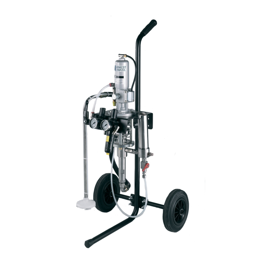
Page 10: Functions
3. Functions 3-1. 13:1 pump unit OPERATING POSITION CLOSE POSITION EMERGENCY STOP POSITION D: EMERGENCY VALVE OPEN POSITION G: CIRCULATION VALVE AIR OUTLET FOR SPRAY GUN FLUID OUTLET AIR INLET Fig.1: Functions (13:1 pump unit) Parts Function Plunger Pump PP-7131N, stainless steel model Pop-off Valve Working pressure: 116psi Air Regulator... - Page 11 3. Functions 3-2. 17:1 pump unit OPERATING POSITION EMERGENCY STOP POSITION D: EMERGENCY VALVE AIR OUTLET FOR SPRAY GUN AIR INLET FLUID OUTLET CLOSE POSITION OPEN POSITION G: CIRCULATION VALVE Fig.2: Functions (17:1 pump unit) Parts Function Plunger Pump PP-1171CNE, stainless steel model Pop-off Valve Working pressure: 116psi Air Regulator...
-
Page 12: Setup
HINT 1. Grounded air hose designed by ANEST IWATA is available. Refer to Fig.1 on page 8 or Fig.2 on page 9 to find reference letters. 1. Place this unit on hard level surface and load uniformly, if stand or cart mount unit. - Page 13 4. Setup 4-3. Checking operation WARNING 1. Never touch moving parts. IMPORTANT 1. Do not keep pump idling for extended periods of time. Prolonged idle operation may cause premature pump failure. Refer to Fig.1 on page 8 or Fig.2 on page 9 to find reference letters. 1.
-
Page 14: Operation
5. Operation WARNING 1. Use in well-ventilated spray booth. 2. Avoid any ignition sources such as smoking, open flames or electrical hazard. 3. Always wear protective clothing, eyewear, gloves and respirator. 4. Never spray toward a person or animals and never pull the trigger of the spray gun near the body. - Page 15 5. Operation 5-2. Preparing for spraying IMPORTANT 1. Always fully close or fully open the circulation valve. Opening the valve halfway can cause seat wear, fluid leakage and lack of fluid pressure. Refer to Fig.1 on page 8 or Fig.2 on page 9 to find reference letters. 1.
-
Page 16: Cleaning
6. Cleaning WARNING 1. Use in well-ventilated spray booth. 2. Avoid any ignition sources such as smoking, open flames or electrical hazard. 3. Always wear protective clothing, eyewear, gloves and respirator. 4. Never spray toward a person or animals and never pull the trigger of the spray gun near the body. -
Page 17: Maintenance
7. Maintenance 7-1. Maintenance cycle Daily 1. Clean fluid passage of pump and spray gun, fluid filters and nozzle tip of spray gun. 2. Check for worn, damaged or broken parts. 3. Drain water from air filter regulator. Every 50 hours 1. -
Page 18: Trouble Shooting
8. Trouble Shooting Refer to Fig.1 on page 8 or Fig.2 on page 9 and 10. Parts List on page 29 - 35 to find reference letters and numbers. Problems Causes Solutions Pump does not operate. Air pressure is not supplied to the Check air compressor and hoses. - Page 19 8. Trouble Shooting Problems Causes Remedies Paint contains air. Air has not been released. Refer to 5-2. Preparing spraying procedure on page 13. Suction Hose Set (E) or Valve Tighten. Adaptor Set (2-58/3-61) is loose. Packing (lower, 2-56/3-59) is worn. Replace.
-
Page 20: Disassembly And Assembly
2. Pay attention to avoid hitting or dropping this unit, especially threaded and seated parts. 3. Never use damaged parts. 4. Repair or replace worn or damaged parts immediately. Always use ANEST IWATA replacement parts. 5. Never modify this unit for any other applications. - Page 21 9. Disassembly and Assembly b) PP-1171CNE (17:1 pump) 1. Loosen the handle and remove the packing. 2. Pull up the nuts and remove. 3. Loosen the head bolt and remove o-ring. 4. Loosen the four bolts and remove the air cylinder and the o-rings from the air motor body.
- Page 22 9. Disassembly and Assembly 9-1-2. Suction section IMPORTANT 1. Clean fluid passage of pump before disassembly of the suction section. 2. Do not damage or bend the rod and be sure to check that the rod is free of foreign matter. It can cause pump malfunction.
- Page 23 9. Disassembly and Assembly 9. Loosen the three nuts and remove the spring washers. 10. Remove the suction body section from the connecting rods. 11. Loosen the wet cup and remove the following parts. Sleeve (or Slide ring) V-packing female adaptor V-packing (upper) V-packing male adaptor - 21 -...
- Page 24 9. Disassembly and Assembly 9-2. Assembly 9-2-1. Air motor section a) PP-7131N (13:1 pump) IMPORTANT 1. Put general-purpose grease on the moving parts, o-rings and packings inside air cylinder. Do not put grease on the parts of the seat block section. 2.
- Page 25 9. Disassembly and Assembly 6. Place the following parts into the air motor body and tighten cap. Interlock piece Packing Interlock end piece Spring 7. Place the seat block section onto the air motor body. 8. Tighten the four bolts and the pipe nut. b) PP-1171CNE (17:1 pump) IMPORTANT 1.
- Page 26 9. Disassembly and Assembly HINT 1. Tighten the nuts on the changeover rod before placing the air cylinder and the head bolt. It is easy to pull up the changeover rod during assembly. 6. Place the o-rings and the air cylinder onto the air motor body and tighten the four bolts.
- Page 27 9. Disassembly and Assembly 9-2-2. Suction section IMPORTANT 1. Be sure to set V-packing set in the correct direction. If not, it can cause pump malfunction. 2. Always replace the four V-packings as set. 3. Do not over tighten the V-packing. It can cause damage to the V-packing during assembly or pump malfunction.
- Page 28 9. Disassembly and Assembly 9. Place the ball and the pin onto the valve adaptor set. 10. Place the packing (lower) onto the suction tube and tighten the valve adaptor set. 11. Place the packing (upper) to the suction body and tighten the suction tube to the suction body.
-
Page 29: Parts List
10. Parts List 10-1. Pump Unit 10-1-1. 13:1 pump unit MSU-114N (Wall Mount) MSU-111N (Stand Mount) MSU-113N (Cart Mount) Description Description Plunger pump, PP-7131N Suction hose set Air regulator set Stand set Circulation valve set Cart set Fluid filter set (option, not shown) - Page 30 10. Parts List 10-1-2. 17:1 pump unit MSU-324N (Wall Mount) MSU-323N (Cart Mount) Description Plunger pump, PP-1171CNE Air regulator set Fluid filter set Suction hose set Cart set - 28 -...
- Page 31 10. Parts List 10-2. Plunger pump (13:1), PP-7131N - 29 -...
- Page 32 10. Parts List Description Description Air cylinder 2-33 Interlock end piece Cap nut 2-34 Packing Piston washer 2-35 Spring Piston packing 2-36 Cap Washer 2-37 Connecting rod O-ring 2-38 Spring washer Air motor rod 2-39 Nut Air pipe joint 2-40 Suction body Pipe nut 2-41 Rod 2-10 Joint nut sleeve...
- Page 33 10. Parts List 10-3. Plunger pump (17:1), PP-1171CNE - 31 -...
- Page 34 10. Parts List Description Description Handle 3-36 Metal Packing 3-37 Stop ring 3-38 Adaptor Head bolt 3-39 Rod O-ring 3-40 Wet cup Air cylinder 3-41 Slide ring Changeover body 3-42 V-packing female adaptor (upper) 3-43 Spacer Changeover pin 3-44 V-packing male adaptor 3-10 Spring 3-45 Connecting rod 3-11...
- Page 35 10. Parts List 10-4. Air regulator set Description Pump base Push-in joint 3-way ball valve Nipple Air regulator Tee joint Nipple Air filter regulator Elbow joint 4-10 Pressure gauge 4-11 Bolt 4-12 10-5. Circulation valve set for 13:1 pump unit Description Elbow joint Tee joint...
- Page 36 10. Parts List 10-6. Fluid filter set for 13:1 pump unit (option) Description Filter plug Cylinder Cap nut Filter bolt Filter 100mesh Packing Packing Filter body Swivel joint 6-10 Spring pin 6-11 Filter adaptor 6-12 Elbow joint 6-13 Nipple 6-14 Elbow joint 6-15 2-way ball valve 6-16 Hose joint 6-17 Locking nut...
-
Page 37: Spray Gun Nozzle Tip Chart
10. Parts List 10-8. Suction hose set Description Suction Hose Circulation Tube Filter Set Filter Cover Filter 50mesh Filter 100mesh (Option) Filter Spring 11. Spray Gun Nozzle Tip Chart Pattern Width: inch (mm) Oriffice Size Fluid Output inch oz/min 5 - 7 7 - 9 9 - 11 11 - 13... - Page 38 Note - 36 -...
- Page 39 Note - 37 -...
- Page 40 Manual Nr. T032-00...
Need help?
Do you have a question about the MSU-111N and is the answer not in the manual?
Questions and answers