Table of Contents
Advertisement
Quick Links
Advertisement
Table of Contents

Related Manuals for Anest Iwata MSU-113 N


Summary of Contents for Anest Iwata MSU-113 N
- Page 1 Use and maintenance manual TI SPRA Y UNIT TI SPRA Y UNIT MSU-113 N MSU-113 N ANEST IWATA Europe s.r.l. 46, Corso Vigevano 10155 Torino - Italia Tel. +39 011-24 80 868 Fax +39 011-85 19 44 www.anest-iwataeu.com ME113NERev.13 e-mail: info@anest-iwataeu.com...
- Page 2 TORINO - ITALY The company The mission of ANEST IWATA EUROPE S.r.l. is to supply all their product and spray painting equipment users and distributors with STATE-OF-THE-ART of technology and with continuous innovation to obtain the best fin- ish at the lowest cost.
-
Page 3: Table Of Contents
GENERAL CONTENTS USE OF THE MANUAL...........................4 SYMBOLS USED ............................4 INFORMATIVE LETTER..........................5 WARRANTY ..............................7 TRANSPORT AND HANDLING......................8 Transport………………………………………………………………………….........8 Transport with cardboard packing………………………………………………........8 Handling………………………………………………………………….............9 Temporary storage……………………………………… .................9 PRODUCT IDENTIFICATION………………………………………………… ........10 Plate data………………………………………………………………… .........……10 Different models………………………………………………………………………… ......10 Technical specifications………………………………………………………… .......……11 Safety systems…………………………………………………………..........…...12 Workable products……………………………………………………………... -
Page 4: Use Of The Manual
Use of the The use and maintenance manual is the document accompanying the equipment from its manufactu- Manual re till its dismantling. Therefore, it is an integral part of the equipment. The manual must be read before starting ANY ACTIVITY involving the equipment including its hand- ling. -
Page 5: Informative Letter
Informative This use and maintenance manual is an integral part of the equipment and it must be easily available letter to the staff in charge of its use. The user and the maintenance man must know the content of this manual. None of the descriptions or pictures contained in this manual are binding. - Page 6 THIS USE AND MAINTENANCE MANUAL DOES NOT MAKE UP FOR ANY DESIGN INADEQUACY. In case of breakdown or malfunction, contact the TECHNICAL CUSTOMER CARE USTOMER ERVICE ANEST IWATA EUROPE s.r.l. C.so Vigevano, 46 - 10155 Torino Telefono +39 011.24.80.868 Telefax +39 011.85.19.44 E-mail: info@anest-iwataeu.com WARNING THE ORIGINAL CONFIGURATION OF THE EQUIPMENT MUST NOT BE CHANGED AT ALL.
-
Page 7: Warranty
Warranty All ANEST IWATA S.r.I products have a one-year guarantee from the invoice date, unless otherwise stated in writing. The warranty covers all manufacturing faults and material defects. Any spare part replacement or repair operations are covered only if they are carried out by our technicians at our servicing shops. -
Page 8: Transport And Handling
1. TRANSPORT AND HANDLING Transport To transport of the equipment, use only the systems described below. In any case make sure that the transport and the lifting device can bear the weight of the equipment with its packaging. WARNING ALWAYS KEEP THE PACKAGING IN A VERTICAL POSITION. WARNING IT IS ADVISABLE THAT THE STAFF IN CHARGE OF HANDLING THE EQUIPMENT WEAR PRO- TECTIVE GLOVES AND SAFETY SHOES. -
Page 9: Handling
Handling To handle the cardboard packaging use a trolley. To handle or displace the multi spray unit only use the cart. WARNING FOLLOW THE INSTRUCTIONS ON THE PACKAGING BEFORE HANDLING AND OPENING IT. HANDLING BY MEANS OF CART HANDLING BY MEANS OF TROLLEY Temporary storage During transport and storage make sure the temperatures between 0 and 40°... -
Page 10: Product Identification
SERIAL NO. Serial number Max. working pressure 0.68 MPa / 6.8 bar / 98 psi MANUFACTURED ANEST IWATA EUROPE s.r.l. C.so Vigevano,46 10155 Torino Italy Year of manufacture CE marking – Environmental limits (environment temperature between + 5°C and + 40°C). -
Page 11: Technical Specifications
Technical specifications Model MSU-113N MSU-113N Model Model with filter Model without filter (Figure 1) (Figure 2) Dimensions 524x500x1020 524x500x1020 Weight 18 Kg 16.5 Kg Pump type PP-7131N (Model in stainless steel) Compression ratio 13:1 Inlet air pipe fitting G1/4” Outlet air pipe fitting G1/4”... -
Page 12: Safety Systems
Safety systems Several safety systems have been conceived during the multi spray unit design and manufacture to safeguard the operator, in compliance with pr EN 12621 Directive about paint. INFORMATION ABOUT SAFETY In case of units, which must work in an environment with a potentially explosive atmosphere the staff in charge, before starting its activities, must disable the unit power supply, by putting it “out of order”... -
Page 13: Workable Products
To use the equipment with special products ask for the approval of the manufacturer. Moreover, the technical features of the unit must be adapted for processing such products. ANEST IWATA is not responsible for any accident due to NON-AUTHORISED and non-qualified personnel using the pump for purposes that are different from the above-mentioned ones. -
Page 14: Operation
3. OPERATION Operation description Multi spray pumps are composed of two main parts: the pneumatic motor and the pumping unit; the pneumatic motor is provided with a pneumatic piston and with a switch for the change of the move- ment direction. The pumping unit is made up of an anti-wear chromium plated suction tube and rod. -
Page 15: Installation And Start
4. INSTALLATION AND START Check the purchased product Before using the pump, make sure it has not been damaged during transport or storage. Also check that all standard components are inside the packaging. Conditions for the installation - The installer must know the ATEX classification of the installation area and also the risks deriving from a potentially explosive atmosphere, especially explosion and fire, so that he can adopt the suit- able protection measures. -
Page 16: Cautions
WARNING - CHECK THE PROPER TIGHTENING OF ALL FITTINGS, SINCE THEIR SUDDEN OPENING CAN SERIOUSLY INJURE PEOPLE. WARNING - CONSULT THE LOCAL CODE FOR DETAILED INSTRUCTIONS CONCERNING THE EARTHING OF THE WORKING AREA AND THE TYPE OF SYSTEM USED. - THE EARTH CABLE (INCLUDED IN THE SUPPLY) MUST HAVE A MINIMUM SECTION OF 1.5 MM2. -
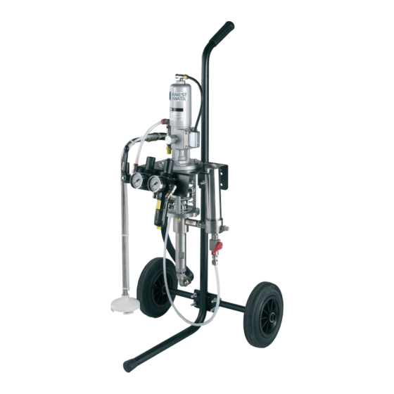
Page 17: Drawing Of The Multi Spray Unit Provided With Paint Filter
Multi spray unit with paint filter FIGURE 2 Pressure regulator G Ground cable Stop position Air outlet G1/4" Ball valve (E) Paint filter (F) Operating position Air inlet G 1/4" Paint outlet G1/4" Adjusting cup (D) Upper packing Recirculation valve (C) Suction hose (A) Recirculation valve (C) CLOSED... -
Page 18: Drawing Of The Multi Spray Unit Without Paint Filter
Multi spray unit without paint filter FIGURE 3 Pressure regulator G Ground cable Stop position Ball valve (E) Air outlet G1/4" Operating position Air inlet G 1/4" Paint outlet G1/4" Adjusting cup (D) Upper packing Suction hose (A) Recirculation valve (C) Recirculation valve (C) CLOSED OPEN... -
Page 19: Use
LIMITS AND CONDITIONS OF USE Any change of the unit can be carried out only if authorised by ANEST IWATA EUROPE technical service. If the change is not authorised, the unit is not considered as ATEX approved. -
Page 20: Prewash And Adjustment Of The Upper Packing
Prewash and adjustment of the upper packing. [Ref. figure 2 page 17 and figure 3 page 18] 1. Make sure the pump has been properly installed; (see point 4.3) 2. Immerse the suction hose (A), in the cleaning liquid (clean solvent or water according to the purchased model). -
Page 21: Start
Never remove the gun trigger safety catch c) Never exceed the maximum working pressure (6.8 bar). d) Always use a multi spray ANEST IWATA gun, which is provided with various safety devices. e) During operation, never touch the moving parts. Before carrying out any maintenance opera-... -
Page 22: Daily Suspensions
Daily interruptions [ref. figure 2 page 17 and figure 3 page 18] 1. Upon interrupting the use of the pump: - It is not necessary to disconnect the air supply, if the interruption is short. - If the interruption period is long, turn the ball valve (E), discharge the air from the circuit and open the recirculation valve (C) to release the residual fluid pressure. -
Page 23: Procedure To Discharge The Pressure
Pressure release process WARNING 1. Close the air supply to the pump by turning the pressure reducer adjustment anticlockwise down to 0 bar. 2. Enable the safety catch of the multi spray gun trigger. 3. Make sure the recirculation pipe is not clogged, then gradually open the recirculation ball valve and leave it open. -
Page 24: Maintenance And Inspection
6. MAINTENANCE AND INSPECTION General notes - Observe the intervals of inspection and ordinary maintenance to ensure suitable working condi- tions and explosive-proof protection. - Before repairing or maintaining the internal parts, wait for the complete cooling of the unit, to pre- vent you from coming into contact with hot parts thus avoiding any burns. -
Page 25: Procedure To Disassemble And Reassemble
Disassembly and re-assembly procedure WARNING Before starting any maintenance operation, remove the air supply pipe and make sure the inner resi- dual pressure has been released. Motor group disassembly 1. Loosen the four bolts (26) and the air hose (11) then remove the seat block (A) from the main body 2. -
Page 26: Re-Assembly Of The Motor Unit
Motor group re-assembly WARNING Remove the air feeding pipes and make sure the residual internal pressure has been released before starting any maintenance operation IMPORTANT 1. Put grease on all the moving components, o-rings and packing located inside the air cylinder. 2. - Page 27 1. Put the stopper (15) on the spindle set (7) NOTE: the following components are assembled on the stopper - stopper (12) washer (13) Y packing (14) O-ring (6) 2. Assemble the following components on the spindle set (7) washer (5) washer (3) [quantity 2] packing (4) then tighten the cap nut (2)
- Page 28 3. Insert the spindle set (7) in the main body (27) 4. Screw the stopper (15) in the main body (27) 5. Screw the adaptor (29) and the spindle set (7); 6. Insert the split pin (28); 7. Screw the air cylinder (1) ;...
- Page 29 8. Lubricate with grease and then insert the following components in the cap (36): spring (35) interlock end piece (33) interlock piece (32) 9. Insert the washer (34) in the main body 10. Screw the cap (36) to the main body 11.
-
Page 30: Disassembly Of The Pneumatic Motor From The Fluid Pump Set
14. Position the packing (22) 15. By using the cross pan-head setscrew (24) screw the exhaust cover (23) to the main body. [The ground cable (60) is anchored to the exhaust cover by means of the cross pan-head setscrew (24) ] Pneumatic motor disassembly from the fluid pump set 1. -
Page 31: Disassembly Of The Fluid Pump Set
Fluid pump set disassembly 1. Secure the suction main body (40), unscrew the suc- tion tube (54) and slip it out. 2. Slip the rod (41) out of the suction main body (40) . 3. Loosen the adjustment nut (47) and remove the upper valve holder set (53). -
Page 32: Maintenance Of The Fluid Pump Set
6.10 Fluid pump set maintenance [ref. figure on page 31] 1. Dip all components in the cleaning liquid and clean them carefully 2. Make sure the rod (41) and the suction tube (54) are not damaged. If they show deep scratches in the sliding area, replace them. -
Page 33: Re-Assembly Of The Motor To The Fluid Pump Set
c) If the packing is too tight their duration shall result extremely reduced. d) A constant and suitable adjustment together with a correct maintenance allows a high packing duration. 2. Do not use grease to lubricate the sliding parts of the pump rod, since it might compromise the following painting operations. -
Page 34: Malfunctions - Troubleshooting
7. TROUBLE SHOOTING Problem Cause Check Solution 1. The air pressure a) The ball valve is not in the a) Make sure the ball valve is in the a) Adjust the ball valve in does not increase. correct position. proper position the proper position b) The air regulator is not open. - Page 35 Problem Cause Check Solution c) Damaged or dirty valves (upper c) Disassemble both and inspect both c) Clean them if they are or lower). the seat and the ball encrusted with solidified paint residues.Otherwise, if they are damaged replace them. d) The lower V packing (inside the d) Disassemble the suction tube and d) If it is enough, adjust them.
- Page 36 Problem Cause Check Solution 9. Paint leakage between the a) Loosened suction tube a) Tighten main body and the suction tube b) The upper V packing (between the main body b) Replace it and the suction tube) is worn out or damaged 10.
-
Page 37: Sections With Spare Parts List
8. SECTIONS WITH SPARE PART LIST Plunger pump set type PP7131N ref. figure on page 38 Pos. Description Quantity Pos. Description Quantity Air cylinder Interlock end piece Cap nut Washer Washer Spring Packing (*) Washer Connecting rod O- ring Spring washer Spindle set Special joint Main body... - Page 38 Plunger pump set type PP7131N...
-
Page 39: Paint Filter
PAINT FILTER SET For MSU 113 N : model with filter Pos. Description Quantity Paint filter set Cylinder Filter body Plug Filter bolt 100 mesh filter Packing Nipple R1/4” M-R3/8” M Two-way ball valve G1/4” FF Hose joint R1/4”M M8x6 Swivel joint R3/8”M-G3/8”F Fluid nipple G3/8”M-G1/4”M DRAIN VALVE SET... -
Page 40: Air Regulator Set
AIR REGULATOR SET For MSU 113 N : model with filter For MSU 113 N : model without filter Pos. Description Quantity Air regulator set Quick joint B.P. 1/4”M 90° Ball ball valve with hexaust hole Nipple G1/4” MM Air regulator G1/4” FF T Joint MFM G1/4”... -
Page 41: Suction Hose Set
STAINLESS STEEL SUCTION HOSE SET For MSU 113 N : model with filter For MSU 113 N : model without paint filter Pos. Description Quantity Suction hose set Suction hose Air hose Complete cover set 3 - 1 Cover M15x1 3 - 2 Filter 50 MESH (100 MESH filter as option) 3 - 3... -
Page 42: Cart Set
CART SET AND PLATE FOR MSU 113 N : MODEL WITH PAINT FILTER FOR MSU 113 N : MODEL WITHOUT PAINT FILTER Pos. Description Quantity Frame set Wheel Split pin Washer U-bolt 1/2 Pump base U -bolt 3/4 Shaft... -
Page 43: Dismantling
9. DISMANTLING Equipment storage If the multi spray unit is to be stored for a certain period, the following operations are recommended: Disconnect the equipment from the energy sources. Remove all residues and deposits from the pump. Cover the equipment with a waterproof tarpaulin. Dismantling If for any reason the pump is to be dismantled, some important rules have to be followed to safeguard the environment. - Page 44 ANEST IWATA Europe S.r.l. Corso Vigevano, 46 - 10155, Torino (Italy) Direct Tel. +39 011 - 22 74 402 Fax +39 011 - 22 74 000 info@anest-iwataeu.com European Sales Branches: www.anest-iwataeu.com ANEST IWATA Italia S.r.l. ANEST IWATA Scandinavia Corso Vigevano, 46 - 10155, Torino (Italy) Ögärdesvägen 6C, 433 30 PARTILLE - Sweden...
Need help?
Do you have a question about the MSU-113 N and is the answer not in the manual?
Questions and answers