Table of Contents
Advertisement
Quick Links
Advertisement
Table of Contents

Related Manuals for Anest Iwata MSU B193


Summary of Contents for Anest Iwata MSU B193
- Page 1 Use and maintenance manual TI SPRA Y UNIT TI SPRA Y UNIT B303 B303 B193 B193 ANEST IWATA Europe s.r.l. 46, Corso Vigevano 10155 Torino - Italia Tel. +39 011-24 80 868 Fax +39 011-85 19 44 www.anest-iwataeu.com e-mail: info@anest-iwataeu.com MAB303ERev.13...
- Page 2 TORINO - ITALY The company The mission of ANEST IWATA EUROPE S.r.l. is to supply all their product and spray painting equipment users and distributors with STATE-OF-THE-ART of technology and with continuous innovation to obtain the best finish at the low- est cost.
-
Page 3: Table Of Contents
TABLE OF CONTENTS USE OF THE MANUAL ..............4 SIMBOLS USED . -
Page 4: Use Of The Manual
Use of the The user and maintenance manual is a document supplied with the equipment from the moment it is manual manufactured to the moment it is destroyed. Thus, it is an integral part of the equipment. It is necessary to read the manual before starting ANY OPERATION (including its handling) on the equipment. -
Page 5: Informative Letter
Other symbols Summary of the user and maintenance manual Trasporto Description of the equipment Installation Normal use Wiring and hydraulic diagrams Dismantling Maintenance operations Informative This instructions manual is an integral part of the equipment and must be readily available for the peo- letter ple in charge of the use and maintenance of the equipment thereof. - Page 6 THIS USER AND MAINTENANCE MANUAL DOES NOT PROVIDE FOR ANY LACK OF PLANNING INFORMATION. In case of equipment failure or abnormal operation, call our TECHNICAL AND CUSTOMER SERVI- CES. USTOMER ERVICE ANEST IWATA EUROPE s.r.l. C.so Vigevano, 46 - 10155 Torino Telefono +39 011.24.80.868 Telefax +39 011.85.19.44 E-mail: info@anest-iwataeu.com WARNING THE ORIGINAL CONFIGURATION OF THE EQUIPMENT MUST NOT BE CHANGED.
-
Page 7: Warranty
Warranty All ANEST IWATA S.r.l. products are guaranteed for one year from the date of the invoice, unless other written agreements have been made. The warranty covers all material and manufacturing defects. It also includes replacing spare parts or repairing faulty parts, which will be carried out exclusively by our workshop. -
Page 8: Transportation And Handling
1. TRANSPORTATION AND HANDLING Transport In order to transport the equipment, it is possible to use only the following systems: Nonetheless, make sure the transport and lifting device are able to carry the weight of the equipment, including its packing material. WARNING: ALWAYS KEEP PACKAGE IN VERTICAL POSITION. -
Page 9: Handling
Handling Use a handtruck for moving cardboard boxes. For moving or handling the multi spray unit, use the handles of the handtruck only. WARNING: IT IS NECESSARY TO FOLLOW THE INSTRUCTIONS ON THE PACKAGE BEFORE IT IS HAND- LED AND OPENED. BOX HANDLING BY HAND TRUCK HANDLING BY HANDTRUCK HANDLES HANDLING BY HOIST... -
Page 10: Identification Of The Product
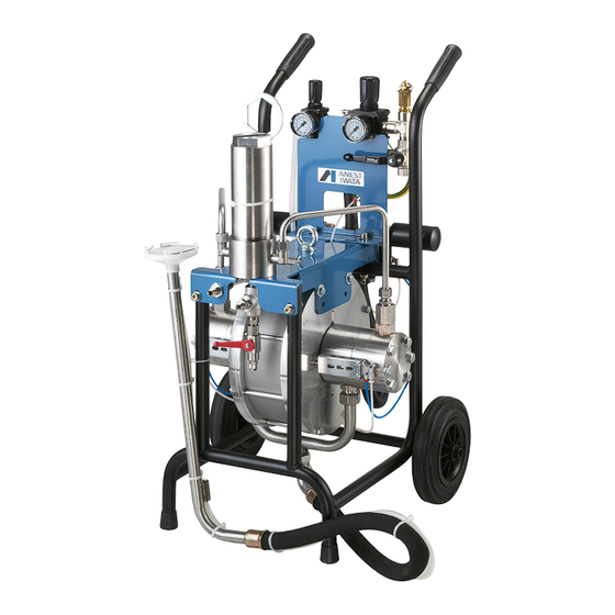
MSU B193 MULTI SPRAY SYSTEM Motor type BM20046, installed on a carrier equipped with an air regulator, exchange valve, check valve, gun atomization adjustment, stainless steel suction and delivery pipes, stainless steel compensator, suction and delivery paint filter, material recirculation. -
Page 11: Technical Specifications
Technical specifications MSU B303 MODEL MSU-B303 Dimensions 555x520x847 Weight 57 Kg Standard pump BM25046 Compression ratio 30:1 Air inlet connector Pipeholder connector for pipe Ø 16mm (inside) Air outlet connector G1/4” Material inlet connector G3/4” Material outlet connector G1/4” Maximum working pressure 6 bars Maximum fluid pressure 180 bars... - Page 12 MSU B193 MODEL MSU B193 Dimensions 555x520x847 Weight 51 Kg Standard pump BM20046 Compression ratio 19:1 Air inlet connector Pipeholder connector for pipe Ø 16mm (inside) Air outlet connector G1/4” Material inlet connector G3/4” Material outlet connector G1/4” Maximum working pressure...
-
Page 13: Safety Devices
Safety devices During the planning and implementation stage of the pumps, different safety devices were conside- red necessary to ensure the safety of users, according to Paint Directive pr EN 12621. INFORMATION ABOUT SAFETY In situations where units need to operate in a potentially explosive atmosphere, the staff in charge must, before starting any activity, switch off the unit and ensure that it is “out of service”... -
Page 14: Uses
Uses The ANEST IWATA MULTI SPRAY pumps have been designed for painting generic ferrous material, wood and plastic. The MSU-B303 and MSU-B193 models are intended for solvent-based and water-based paint with medium or high viscosity. In order to use the equipment with specific products, it is necessary to obtain an approval from the manufacturer as well as the adaptation of the unit’s technical specifications for processing... -
Page 15: Operation
3.OPERATION Description of operation Multi spray pumps are composed of two main parts: the pneumatic motor and the pumping unit; The pneumatic motor is provided with a pneumatic piston and two air inlets for changing the direction of motion. IMPORTANT: it is recommended to supply the unit by using pipes with an inside diameter of at least 15 mm. -
Page 16: Installation And Startup
4. INSTALLATION AND STARTUP Checking the purchased product Before using the pump, make sure it has not been damaged during transport or storage. Also check that all standard components are inside the package. Conditions for the installation - The installation technician must be aware of the ATEX class of the installation area, as well as the risks associated with the presence of a potentially explosive atmosphere, with particular attention to explosion and fire hazards, and thereby adopt the necessary safety precautions. -
Page 17: Precautions
WARNING: - CHECK THE PROPER TIGHTENING OF ALL FITTINGS, SINCE THEIR SUDDEN OPENING CAN SERIOUSLY INJURE PEOPLE. WARNING: - CONSULT THE LOCAL CODE FOR DETAILED INSTRUCTIONS REGARDING GROUND CONNEC- TIONS IN THE WORK AREA AND THE TYPE OF SYSTEM USED. - THE GROUND CABLE (INCLUDED IN THE SUPPLY) MUST HAVE A MINIMUM SECTION OF 1.5 mm2. -
Page 18: Multi Spray Unit Drawing Msu-B303
Multi Spray Unit MSU_B303 FIGURE 2 Pressure regulator (G) Paint filter (F) Working position Eye bolt Air inlet Three way valve (E) Ø 15 Stop position Ground cable (D) Fluid outlet G 1/4” Air outlet (closed) G 1/4” Suction tube (A) Recirculation Valve (C) (open) -
Page 19: Use
If the system is used improperly, it could break down, thereby causing serious damage. Use the multi spray unit for professional purposes only. Do not modify or change the system; use only Anest Iwata original spare parts. Check the system daily: repair or replace all worn or damaged parts immediately. -
Page 20: Prewash
Prewash [See figure 2 and figure 3 page 18] 1. Make sure the pump has been properly installed; (see paragraph 4.3). 2. Immerse the suction pipe (A) in the cleaning liquid (clean solvent or water). 3. Place the three-way valve (E) in the operating position. 4. -
Page 21: Starting Up
Never remove the gun trigger guard. c) Never exceed the maximum working pressure (6 bars). d) Always use a multi spray ANEST IWATA gun, which is provided with various safety devices. e) During operation, never touch the moving parts. Before carrying out any maintenance opera-... -
Page 22: Daily Interruptions
Daily interruptions [ See figure 2 and figure 3 page 18] 1. When the use of the pump is temporarily stopped: It is not necessary to disconnect the air supply if the interruption is short. If the interruption is long, turn the three-way valve (E), thereby releasing the air from the circuit, and open the recirculation valve (C) to release the residual fluid pressure. -
Page 23: Pressure Release Process
Pressure release process [See figure 2 and 3 page 18] WARNING 1. Close the air supply on the pump by turning the air pressure reducer control (G) counter-clockwi- se down to 0 bar. 2. Activate the safety catch of the multi spray gun trigger. 3. -
Page 24: Maintenance And Inspection
6. MAINTENANCE AND INSPECTION General notes - Observe the routine inspection and maintenance schedule to ensure suitable operating conditions and the effective explosion protection of the unit. - Before servicing or repairing internal components, allow the unit to cool down completely before opening it so as to avoid burns from parts which are still hot. -
Page 25: Removing The Hydraulic Motor
Removing the hydraulic motor Use the air regulator to move the limit switch rod (A) to the opposite side relative to that to be removed (then release the air and disconnect the supply pipes as described in paragraph 6.4). Remove the delivery pipe assembly (1) by unscrewing the nuts (2a) and (2b). -
Page 26: Hydraulic Motor Group Assembly
Hydraulic motor group assembly - Place the new bellows (14) onto the chromium plated shaft (4). - Fit the bellows flange (26). - Fit the piston (16) onto the bellows (14). - Completely tighten the screw (18) and washer (17) into the chromium plated shaft (4). -
Page 27: Hydraulic Motor Maintenance
- Position the limit switch (42) and the limit switch cover plate (44) by fastening them onto the hub with the screws (43). - Position the suction pipe assembly (7) and tighten the nuts (6). - Position the delivery pipe assembly (1) and tighten the nuts (2a) and (2b). - Page 28 IMPORTANT: Before positioning the delivery pipe assembly (1), make sure the ferrules (2c) and (2d) are fastened to the pipe; the ferrules must be free to turn around the pipe but must not come off. - Position the delivery pipe assembly (1) as shown in the picture and lubricate the following compo- FIGURE B nents with oil: ferrules (2c and 2d);...
-
Page 29: Removing Delivery Pipes
Removing delivery pipes Unscrew the nuts (2a) and (2b) symmetrically. IMPORTANT: When removing the nut (2b), tighten the connector (2c) with a second wrench by pushing clockwise. 6.10 Installing the suction pipe Lubricate the following components with oil: connector thread (6b); furrule (6a); nut thread (6). Position the suction pipe assembly (7) as shown in the picture. -
Page 30: Tests To Be Carried Out After Reassembly
6.11 Tests to be carried out after reassembly 1. The pump must start up with a supply pressure of at least 0.5 bar. 2. Make sure there are no air or paint leakages. If necessary, tighten the parts involved. 6.12 Paint filter maintenance If the pump is properly used (a thorough cleaning should be carried out each time it is used) the paint filter will not require special maintenance operations except those regarding cleaning and replacement of the fil-... -
Page 31: Troubleshooting
7. TROUBLESHOOTING Problem Cause Check Solution 1. The air pressure a) The three-way valve is not in the a) Make sure the three-way valve is in the a) Adjust the three-way valve in does not increase. proper position. proper position the proper position b) The air regulator is not open. - Page 32 Problem Cause Check Solution 4. The pump does c) Damaged or dirty valves c) Disassemble both and inspect c) Clean them if they are not stop (upper or lower) the seat as well as the ball. encrusted with solidified paint residues.Otherwise, if they are damaged replace them.
- Page 33 Problem Cause Check Solution 9. The pump stops and a) The pneumatic limit switch a) If it is dirty, clean it; if it is worn out, air comes out of is dirty or worn out. replace it. the exchange valve. 10.
-
Page 34: Spare Parts List
QTY Note Pump body set BM25046 (for MSU B303) List of spare parts page 36 paragraph 8.2 Pump body set BM20046 (for MSU B193) List of spare parts page 38 paragraph 8.3 Paint filter set TF10N List of spare parts page 40 paragraph 8.4 Air operating valve set List of spare parts page 41 paragraph 8.5... - Page 35 FIGURE 1...
-
Page 36: Spare Parts List For Motor Bm25046
SPARE PARTS LIST - MOTOR BM25046 (installed on unit MSU-B303); See figure page 37 Item Description Pneumatic cylinder 250 Flange O-ring M250 Motor flange 250 Piston D 249 Piston O-Ring M250 Push rod D 12 Hex. socket cap screw 14.9 M8x50 UNI 5923 O-ring F18 Bellows washer D 51x1.6 Bellows ID 18... - Page 37 EXPLODED VIEW – MOTOR BM25046...
-
Page 38: Spare Parts List For Motor Bm20046
SPARE PARTS LIST - MOTOR BM20046 (installed on unit MSU-B193); [See figure page 39] Item° Description Pneumatic cylinder 200 Flange O-ring PL28; N111; M200 Motor flange 200 Piston Push rod D 12 Hex. socket cap screw 14.9 M8x30 UNI 5923 O-ring F18 Bellows washer D 51x1.6 Bellows ID 18... - Page 39 EXPLODED VIEW – MOTOR BM20046...
-
Page 40: Spare Parts List Paint Filter Set
SPARE PARTS LIST - PAINT FILTER SET For MSU-B303 and MSU-B193 Item Description Paint filter set Cylinder D 75 Filter plug 3/8” F Filter 100 mesh Filter spring Screw Packing D 75 Body Elbow hose joint R3/8”M Nipple R3/8”MM T- joint G3/8”FFF Nipple R3/8”M –... -
Page 41: Spare Parts List Air Operating Valve Set
SPARE PARTS LIST - AIR OPERATING VALVE SET For MSU-B303 and MSU-B193 Item Description Air operating valve set Silencer G3/4"M Reducer R1/2”M – G3/4”F Elbow R1/2”M G1/2”F Nut M6 (OPTIONAL) Washer D 6 (OPTIONAL) Screw M6x50 (OPTIONAL) Quick swivel joint G1/8”M Air operating valve G1/2”F Hexagon nut M3 Washer D 3... -
Page 42: Spare Parts List Air Regulator Set
SPARE PARTS LIST AIR REGULATOR SET For MSU-B303 and MSU-B193 Item Description Air regulator set Quick swivel joint G1/4”M Air regulator with filter G1/4” FF Nipple R1/4”M-R1/4”M Reducer G1/2”M-G1/4”F T- Joint R1/2”M-G1/2”FF M5F Air regulator G1/2”FF Nipple R1/2”M-R1/2”M T-Joint R1/2”M-G1/2”FF Safety valve R1/2”M 3-Way ball valve G1/2”FFF Silencer G1/2"M... -
Page 43: Spare Parts List Suction Hose Set
SPARE PARTS LIST - STAINLESS SUCTION HOSE SET For MSU-B303 and MSU-B193 Item Description Suction hose set Suction hose Recirculation pipe Complete cover set 3 - 1 Cover 3 - 2 Filter 30 mesh 3 - 3 Spring stopper FIG.A... -
Page 44: Spare Parts List Wheel Cart Set
SPARE PARTS LIST - WHEEL CART SET For MSU-B303 and MSU-B193 Item Description Wheel cart set Frame Handgrip Wheel Split pin Rubber foot FIG.A... -
Page 45: Spare Parts List Delivery Pipe Set
SPARE PARTS LIST DELIVERY PIPE SET Item Description Delivery pipe set Stainless steel pipe D 12x9 Nut M18x1.5 Ferrule for pipe D 12 *items available only in designated assembly FIG.A 8.10 SPARE PARTS LIST SUCTION PIPE SET Item Description Suction pipe set Stainless steel pipe D 22x19 Nut M30x2 Ferrule for pipe D 22... -
Page 46: Dismantling
9. DISMANTLING Equipment storage If the multi spray unit is to be stored for some period, the following operations are recommended. Disconnect the equipment from the energy sources. Remove all residues and deposits from the multi spray unit. Cover the equipment with a tarpaulin sheet. Dismantling If for any reason the multi spray unit is to be dismantled, some important rules must be followed in order to protect the environment. - Page 47 NOTE...
- Page 48 ANEST IWATA Europe S.r.l. Corso Vigevano, 46 - 10155, Torino (Italy) Direct Tel. +39 011 - 22 74 402 Fax +39 011 - 22 74 000 info@anest-iwataeu.com European Sales Branches: www.anest-iwataeu.com ANEST IWATA Italia S.r.l. ANEST IWATA Scandinavia Corso Vigevano, 46 - 10155, Torino (Italy) Ögärdesvägen 6C, 433 30 PARTILLE - Sweden...
Need help?
Do you have a question about the MSU B193 and is the answer not in the manual?
Questions and answers