Table of Contents
Advertisement
Quick Links
Advertisement
Table of Contents

Summary of Contents for Honda Hondex HE-773-III-Di
- Page 2 INTRODUCTION Thank you very much for purchasing our product. Please be sure to read this operating manual carefully and understand the contents before the actual operation in order to keep your safety. Please store this manual safely at the convenient place so that you can read it when needed.
-
Page 3: Table Of Contents
TABLE OF CONTENTS CAUTION ON SAFETY (BE SURE TO READ THIS) ······································ 1 1. HANDLING OF MAIN UNIT ································································ 1 2. HANDLING OF CABLE ····································································· 2 3. HANDLING OF TRANSDUCER AND WATER TEMP SENSOR ················· 3 4. HANDLING OF REMOTE ··································································· 3 5. - Page 4 EACH TILT ANGLE (SONAR MODE) ······················································· 27 OVERLAP DISPLAY MODE (SONAR MODE) ············································ 28 EACH SCAN DIRECTION (BOTTOM SONAR MODE) ································· 29 SAVE IMAGE TO MEMORY CARD ·························································· 30 MEMORY CARD ··················································································· 31 DISPLAY RANGE ················································································· 32 SHIFT (DISPLAY RANGE SHIFT) (SOUNDER MODE) ································· 33 SLOW SCAN SPEED (SONAR MODE) ·····················································...
- Page 5 WATER TEMP ALARM ·········································································· 48 OUTPUT POWER ················································································· 48 PULSE LENGTH ·················································································· 49 SENSITIVITY MODE ············································································· 49 SCALE LINE (BOTTOM SONAR/SOUNDER MODES) ································· 50 WATER TEMP CORRECTION ································································· 50 VOLTAGE CORRECTION······································································· 51 INITIALIZATION ··················································································· 51 RESET TRANSDVCER ·········································································· 52 FREQUENCY CHANGE ········································································· 53 DEPTH UNIT ························································································...
-
Page 6: Caution On Safety (Be Sure To Read This)
CAUTION ON SAFETY (BE SURE TO READ THIS) This section explains the important cautions in order to prevent the users and surrounding people from physical injuries and property damages. 1. HANDLING OF MAIN UNIT High voltage is used for the unit inside. No one besides authorized personnel should disassemble or modify the unit. -
Page 7: Handling Of Cable
Do not install the unit where rain or spray dashes hit directly. It causes firing and heating. Do not install the unit at heated places. It causes the firing from the increase of internal temperature, injury, and electronic shock. Use the earthing. Noise influence can be prevented by firm earthing. -
Page 8: Handling Of Transducer And Water Temp Sensor
3. HANDLING OF TRANSDUCER AND WATER TEMP SENSOR Any works on the vessel are very unstable and risky. Installation/maintenance of transducer and water temp sensor should be handled after landing the vessel on ground or fixing the vessel at shipyard etc. Water proof treatment is required for Thru-Hull installation. -
Page 9: Caution Of Operation
6. CAUTION OF OPERATION Power OFF when Starting Engine Battery voltage varies when the engine starts. It may cause some damage onto the unit. Set the power OFF when starting the engine. Power Supply 11~30V Operate the unit within the range of DC 11~30V. Organic Solution is Prohibited Do not clean the unit with organic solution like thinner or alcohol etc because most parts are made with plastic. -
Page 10: Basic Feature
BASIC FEATURE Mode Transducer Frequency Bottom Multi Scan Area Sonar Sounder Sonar 180° Hemisphere TD303 290kHz Full swing 180° Hemisphere TD304 240kHz Full swing... -
Page 11: Display
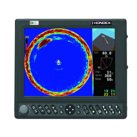
DISPLAY Sonar Mode Example Animation Distance Scale Reflection Freq Tilt Tilt Display Scan Step Gain Bar Display Range Step Stector (Sector) Range Range Water Temp Bottom Voltage Ship Color Pattern GPS mark Auto hull unit indicator When connecting to optional water temp sensor. 2 Only when auto hull unit is selected Bottom Sonar Mode Example Ship... - Page 12 Sounder Mode Example Auto hull unit indicator Fish School GPS mark Freq Gain Bar Bottom Depth Range Color Pattern 1Water Temp Voltage Echo Depth When connecting to optional water temp sensor. 2 Only when auto hull unit is selected. [RSE] “RSE”...
-
Page 13: Description
DESCRIPTION 1. FRONT VIEW OF MAIN UNIT POWER / BRIGHTNESS (p12) Power ON/OFF and adjustment of display brightness. USER KEY <A~H> Set-up the tilt motor angle for 4-Display or overlap mode.(p27, 28) Set-up the scan direction for 4-Display mode.(p29) Set-up the shift ( display range shift). (p33) Set-up the gain for sounder mode. -
Page 14: Rear View Of Main Unit
2. REAR VIEW OF MAIN UNIT TD Connector Plate A+B Fix the plate B on to TD connecto and tighten it with wing bolt. TD Connector Plate B Wing Bolt TD Connector (12P) TD Connector Plate A Water temp sensor (8P) (optional) Auto hull unit controller (8P) (optional) NMEA(GGA,VTG or RMC) output device(6P) Remote (4P) (optional) -
Page 15: Remote (Optional)
3. REMOTE (Optional) DIRECTION (Up/Down/Left/Right) 6RQDU (p14) %RWWRP 6RQDU When opening the menu, it moves the selected item and changes the set-up. 6RXQGHU PRGH When not opening the menu, Up/Down keys, , moves the range of manual expansion, and Left/Right keys, moves the marker toward water surface or bottom direction. - Page 16 About handling remote control (option) Locate the remote to safe spot against vibration etc when not in use. It may cause injury and accidents. · Remote (CR06) is the wired specs only. Wireless not supported.
-
Page 17: Power On / Off
POWER ON / OFF Power Power/Brightness Turn the power/brightness potentiometer potentiometer clockwise so that the power is set to ON. The power lamp is lit, and display will activate. Turn the power/brightness potentiometer counter-clockwise so that the power is set to OFF. -
Page 18: Transducer Set-Up
TRANSDUCER SET-UP TD Set-up The following display appears for factory set-up and initialized condition. Press SET button or right direction button for set-up display. Transducer is not selected. Set Frequency. <CAUTION> Incorrect setting may damage transducer and unit. SET OR TO SELECT TD TD set-up Select the frequency from 1. -
Page 19: Menu
MENU Menu Change the set-up with [MENU] / [DIRECTION] / [SET] / [CLR] keys. MENU DIRECTION [MENU] key Press MENU key to display Menu 1. Press MENU key again to display Menu 2. Press MENU key with water temp alarm display to return to Menu 2. [DIRECTION] key, To move the selected item. -
Page 20: Sonar Mode Switch
SONAR MODE SWITCH Switches to Sonar, Bottom Sonar, or Sounder Mode. The transducer set-up will take sometimes during mode change. Mode Button Press key to change the mode. [Sonar Mode] – [Bottom Sonar Mode] – [Sounder Mode] This key does not work when menu is opened. Mode Button Menu Button Go to Menu1 –... -
Page 21: Scan Direction (Sonar/Bottom Sonar Modes)
(SONAR / BOTTOM SONAR MODES) SCAN DIRECTION Rotate the detecting direction from ship location. Sonar Mode Possible to change the scan direction in 1.8° steps. key to rotate clockwise. key to rotate counter-clockwise. Train Counter-Clockwise Clockwise Search Area... - Page 22 Bottom Sonar Mode Range: 0°~180° in 1.8° steps. 0°: Forward direction for right display, 180°: Forward direction for left display key to rotate clockwise key to rotate counter-clockwise. Train Scan direction: Scan direction: Counter-clockwise Clockwise Angle for train center location Train center is shown in red color.
-
Page 23: Tilt Angle (Sonar/Bottom Sonar Modes)
(SONAR / BOTTOM SONAR MODES) TILT ANGLE Change the tilt angle SONAR MODE Range: 0°~90° in 1° step. (0°: forward (water surface) direction, 90°: vertical direction) moves to upward. moves to downward. TILT Change this tilt angle moves to upward TILT moves to downward Display max. - Page 24 Bottom Sonar Mode Possible to rotate in 1.8° steps. Range: Max.120° moves the target area to clockwise. moves the target area to counter-clockwise. TILT Clockwise shift Counter-clockwise shift Change center direction and angle...
-
Page 25: Detection Range (Sonar/Bottom Sonar Modes)
(SONAR / BOTTOM SONAR MODES) DETECTION RANGE Switch the detectable range (angle). for narrower angle, for wider angle. Range Button Sonar Mode Choose from 9 different sectors. 30°, 60°, 90°, 120°, 150°, 180°, 240°, 300°, 360° 6KNV 5VGR 5GEVQT 4GPIG Display the selected angle Change this angle Bottom Sonar Mode... -
Page 26: Sweeping Step (Sonar/Bottom Sonar Modes)
(SONAR / BOTTOM SONAR MODES) SWEEPING STEP Sweeping Step Select the moving angle for the transducer. Go to MENU1 – STEP. S1~S6 : Fine steps for S1, but at slow speed compared to S6. For some case, the selected step is not executed with sonar mode. Both selected and activated steps are shown on the screen. -
Page 27: Ship Mark (Sonar/Bottom Sonar Modes)
SHIP MARK(SONAR / BOTTOM SONAR MODES) Ship Mark Ship mark is displayed on the screen. Ship mark tells you the direction of ship visually. Go to MENU1 – 2. SHIP MARK. OFF Mark OFF Mark ON No ship mark appears with 4-Display mode (p.25) (SONAR/BOTTOM SONAR MODES) OFF-CENTER MODE Display Off-Center image by expanding the target area. - Page 28 Off-Center Mode(Bottom Sonar Mode) Possible to shift the screen left / right. Press to change Left Right OFF . Off-Center Button Left Right Ship...
-
Page 29: Animation Display (Sonar/Bottom Sonar Modes)
(SONAR / BOTTOM SONAR MODES) ANIMATION DISPLAY Animation Display 3D-like animation appears on the upper-right display showing on-going emission direction. Select “4. ANIMATION”. ON: Animation ON OFF: Animation OFF (Scan or Tilt display is shown instead.) [Animation Display] Display the center angle. [Scan Display (Sonar Mode only)] Scan Secter Train center is shown red color. -
Page 30: 4-Display Mode (Sonar/Bottom Sonar Modes)
(SONAR / BOTTOM SONAR MODES) 4-DISPLAY MODE Set-up different tilt angles for quad-split display. Refer to “Display Order (4-Display Mode)” (p26) for the details of display order. 4-Display Mode Press to enable/disable 4-Display. Quad-Split Display Step Step Sector Sector Range Range [Example of Display of Bottom Sonar Example display of sonar... -
Page 31: Display Order (4-Display Mode)
(4-DISPLAY MODE) DISPLAY ORDER Display Order (4-Display Mode) SONAR MODE Go to MENU1 – 7.OTHER SONAR. BOTTOM SONAR MODE Go to MENU1 – 5.OTHER BOTTOM SONAR. Select the display order for 4-Display mode. Step Step Sector Sector Range Range... -
Page 32: Each Tilt Angle (Sonar Mode)
(SONAR MODE) EACH TILT ANGLE Tilt Direction Change The following buttons are assigned for the set-up of each tilt angle. Buttons Upper Left Upper Right Lower Left Lower Right Tilt Angle Pressing TILT button changes all tilts spontaneously. Upper Left Tilt Angle Upper Right Tilt Angle Lower Left Tilt Angle Lower Right Tilt Angle... -
Page 33: Overlap Display Mode (Sonar Mode)
(SONAR MODE) OVERLAP DISPLAY MODE Overlap Display Mode Overlap Display Mode to compose displays with multiple tilt angles on 1 full display can be selected . On Overlap Display Mode , information of three patterns of tilt angle is shown on 1 full display with different colors . -
Page 34: Each Scan Direction (Bottom Sonar Mode)
(BOTTOM SONAR MODE) EACH SCAN DIRECTION Scan Direction Change The following buttons are assigned for the set-up of each scanning direction. Buttons Upper Left Upper Right Lower Left Lower Right Pressing TRAIN button changes all scan directions spontaneously. Upper Left Scan Direction Upper Right Scan Direction Lower Left Scan Direction Lower Right Scan Direction... -
Page 35: Save Image To Memory Card
SAVE IMAGE TO MEMORY CARD Possible to save the displayed image into memory card, KD05-C-P.(optional) The file format/size is BMP(bitmap)/640x480 which is easy to handle with PC for print- out etc. Caution) You can not see it with this machine. Save Image Go to MENU2 –INITIALIZE –... -
Page 36: Memory Card
MEMORY CARD Memory Card] Possible to copy the data between unit and memory card. Recommended to use the memory card supplied by Hondex. Remove the cover on the card slot. The sticker on memory card should be facing the operator. Insert the memory card Card Slot Cover into the slot. -
Page 37: Display Range
DISPLAY RANGE Display Range Set-up the display range on the screen (depth from water surface). Case of Sonar Mode: Beam length (distance of tilted distance from the ship) Tilt Step Sector Range Distance [Shallower Display Range] Press to make it shallower. [Deeper Display Range] Range Press... -
Page 38: Shift (Display Range Shift) (Sounder Mode)
(SOUNDER MODE) SHIFT (DISPLAY RANGE SHIFT) Shift (Shift of Display) Possible to shift the display range. For example, initial displayed range becomes to 4m and display range becomes 4-12m when shifting to 4m downward at 0-8m depth range. Also, using expand feature would help to enlarge the target area much bigger. [BEFORE] [AFTER] 4m shift... -
Page 39: Slow Scan Speed (Sonar Mode)
(SONAR MODE) SLOW SCAN SPEED The reflected echo from sea bottom might appear when using shallow range than the actual depth (distance). Slow the scan speed to decrease or eliminate the ghost image. Scan Speed Set-up Go to MENU1 – 7.OTHER SONAR. Go to 2.SCAN SPEED. -
Page 40: Sensitivity
SENSITIVITY Digital sounder is capable of changing the sensitivity for whole screen (past image) spontaneously. This feature makes easy manual setting possible by sensitivity adjustment while looking at the past image. Independent sensitivity setting is possible in sonar mode, bottom sonar mode, fish finder mode respectively. - Page 41 Gain Adjustment (Sounder Mode) Select 1 screen display, 2 screen display by menu. ( p39) Single Freq [Lower Sensitivity] Press , user key B , or user key D , to lower the sensitivity. [Higher Sensitivity] Press , user key A , or user key C , to increase the sensitivity.
-
Page 42: Near/Far Gain (Sonar Mode)
(SONAR MODE) NEAR/FAR GAIN Near/Far Gain Change the individual gain set-up for near/far distance. Possible to increase the sensitivity only for far distance. Lowering the sensitivity for near distance reduces the reflections of plankton or water surface. Go to MENU1 – 5. NEAR/FAR GAIN. Press [SET] key. -
Page 43: Near/Far Gain Distance Set-Up (Sonar Mode)
(SONAR MODE) NEAR/FAR GAIN DISTANCE SET-UP Near/Far Gain Distance Set-up Possible to change the distance applied for NEAR/FAR GAIN (p37) Go to MENU1 – 7.OTHER SONAR – 3.NEAR/FAR GAIN TYPE. Select the type. S or L Short: 0, 10, 20, 50m Long: 0, 20, 40, 100m (SONAR MODE) MARKER... -
Page 44: Depth Marker (Bottom Sonar/Sounder Modes)
(BOTTOM SONAR / SOUNDER MODES) DEPTH MARKER Depth Marker Press to display the depth marker line moving downward. Press to move the marker upward. The marker depth figure appears on the line. Depth Marker Line Depth Left Key (Line moves upward.) Right Key (Line moves downward.) DISPLAY SWITCH... -
Page 45: Sweeping Speed (Sounder Mode)
(SOUNDER MODE) SWEEPING SPEED Sweeping Speed Sounder display consists of the consecutive latest image (image beneath the vessel) at the right edge and keep shifting the past image to the left side. Sweeping speed is the speed to shift the image. Whole display appears differently with this set-up value. [Relation between Sweeping Speed and Sounding Rate] Sweeping speed can be selected from 6 different types. -
Page 46: A-Mode (Sounder Mode)
(SOUNDER MODE) A-MODE A-Mode A-mode appears between sounder image and depth indication. The width changes depending on the strength of reflected echo signal. Select MENU1 – SOUNDER – 2. A-MODE. Set 2. A-MODE. A-Mode ON A-Mode OFF (SOUNDER MODE) EXPANSION RATIO Expansion Mode [Expansion Display] Expanded display appears on the left side of screen. -
Page 47: Shift Expansion Position (Sounder Mode)
Expansion Ratio Expansion ratio can be selected from 2x, 4x, 8x. Select MENU1 – SOUNDER – 4. EXP RATE. Set 4. EXP RATE. (SOUNDER MODE) SHIFT EXPANSION POSITION Shift Expanded Area Possible to move the expanded area toward water surface or bottom side. Select the expansion ratio from x2, x4, x8. -
Page 48: Water Temp Graph (Sounder Mode)
(SOUNDER MODE) WATER TEMP GRAPH Water Temp Graph Water temp graph appears. It’s easy to see the fishing points by knowing the variation of water temperature and tide change. Select MENU1 – SOUNDER – 5.OTHER SOUNDER – 2. TEMP GRAPH. Select 2. -
Page 49: Depth Alarm (Sounder Mdoe)
(SOUNDER MODE) DEPTH ALARM Depth Alarm [Depth Alarm] Alarm is ON within or exceeding the range of 2 different depth (Depth Set1, Depth Set2). Select MENU1 – SOUNDER – 5.OTHER SOUNDER – 4.DEPTH ALARM – 1.ALARM SET. Select 1.ALARM SET IN Range Alarm is ON within the range of 2 selected depth. -
Page 50: Super Range (Sounder Mdoe)
(SOUNDER MODE) SUPER RANGE Super Range Whole past image changes automatically according to the current depth (displayed depth range on screen) if changed any. Select MENU1 – SOUNDER – 5.OTHER SOUNDER -5.SUPER RANGE Select 5.SUPER RANGE. No Use (SOUNDER MODE) DEPTH DISPLAY Depth Display Select the display size of depth digit. -
Page 51: Background Color
BACKGROUND COLOR Background Color Visual image of display looks differently by surrounding brightness. It is easier to see the image by selecting the background color from 4 different colors. Select MENU2 – 1.BACK GROUND . Select 1.BACK GROUND . (black, cyan, blue, white) COLOR TONE Color Tone Set-up the color tone of display. -
Page 52: Color Erase
COLOR ERASE Color Erase Fish schools and sea bottom are displayed on screen according to the reflected echo and selected color pattern. “Color Erase” function deletes the color of the weakest reaction one by one so that fish schools can be judged easier by erasing the colors of planktons or dirt inside the water. -
Page 53: Water Temp Alarm
WATER TEMP ALARM Water Temp Alarm Alarm is ON within or exceeding the range of 2 different water temp. Optional water temp sensor is required for water temp alarm. Select MENU2 – 4. TEMP ALARM – 1.ALARM SET. Select 1.ALARM SET-UP. IN RANGE Alarm is ON within the range of 2 selected temp. -
Page 54: Pulse Length
PULSE LENGTH Pulse Length Basic set-up is normal for pulse length, but it is possible to select the pulse length. Selecting “Short” means 2 half shorter pulse compared to normal. Select MENU2 – 6.PULSE LENGTH. Select 6.PULSE LENGTH. SHORT Shorter detectable range, but higher resolution. -
Page 55: Scale Line (Bottom Sonar/Sounder Modes)
(BOTTOM SONAR / SOUNDER MODES) SCALE LINE Scale Line Horizontal line (scale line) appears on the screen. Select MENU2 – 8.SCALE LINE. Select 8.SCALE LINE. OFF No Use WATER TEMP CORRECTION Water Temp Correction Correct the water temperature. Select MENU2 – 9.ADJUST -1. TEMP.CORRECT. -
Page 56: Voltage Correction
VOLTAGE CORRECTION Voltage Correction Corrects the voltage when indicated voltage differs from actual one. Select MENU2 – 9. ADJUST – 2.VOLT.CORRECT. Select 2.VOLT CORRECT. -3.0V +3.0V INITIALIZATION Initialization Initialize all the set-up. Select MENU2 – 0.INITIALIZE – 1.INITIAL ALL. 1.INITIAL ALL. Press SET button to start the initialization. -
Page 57: Reset Transdvcer
RESET TRANSDUCER TD Set-up Select MENU2 – 0.INITIALIZE – 2.TD SET-UP. Use direction button to select one transducer. TD Set-up Select the frequency from 1.SELECT TD. TD303:290kHz TD304:140~240kHz SCAN_PORT Set-up Be sure to set-up SCAN_PORT every time after changing the transducer. To select hull unit Select the hull unit to use. -
Page 58: Frequency Change
FREQUENCY CHANGE Freq Set-up Possible to change the freq when using TD304. Go to MENU2-0.INITIALIZE-6.FREQ SET UP. Press key. Key : Lower Freq Key : Higher Freq MENU key : close the box Close the freq. set-up box tocomplete. DEPTH UNIT Depth Unit Select from “Meter “... -
Page 59: Auto Hull Unit
AUTO HULL UNIT When you use auto hull unit, please select "AUTO" for HULL UNIT of TD SET-UP (p.13,51)."Auto Hull Unit Indicator" appears on the display. UP/DOWN of auto hull unit is enabled. Please operate UP/DOWN of auto hull unit when the vessel is in still condition. (3 knots or less speed). -
Page 60: Nmea Input
NMEA INPUT USAGE OF GPS DATA When you input NMEA data (GGA, VTG or RMC) relating to positioning into the unit, GPS mark is shown. ( Unless positioning, GPS mark is not shown.) When GPS mark is shown (when positioning), some functions of hoist unit becomes effective. -
Page 61: Ir (Sonar/Bottom Sonar Modes)
IR (Interference Rejection : SONAR/BOTTOM SONAR MODES) IR may reduce the level of interference from other sounders. SONAR MODE Go to MENU1-Other Sonar Setup. Bottom Sonar Mode Go to MENU1-Other Bottom Sonar Setup. 0. NORMAL : No IR 1. IR-1 : Same scan speed but lover Sensitivity. -
Page 62: Menu List
MENU LIST Factory set-up: Items shown with underlined block letter <MENU 1> Sonar 1. STEP [ S1 , S2 , S4 ,S6, S6F ] 2. SHIP MARK [ OFF , ON ] 3. MODE [SONAR, BTM SONAR, SOUNDER] 4.ANIMATION [ OFF , ON ] 5.NEAR/FAR GAIN 6.OVERLAP [ OFF , ON ]... - Page 63 <MENU 1> Sounder 1. SWEEP [ STOP , 1 , 2 , 3 , 4 , S ] 2. A-MODE [ OFF , ON ] [ OFF , BOTTOM LOCK , AUTO-EXP , 3. EXP MODE MANUAL-EXP ] 4. EXP RATE [ ×2 , ×4 , ×8 ] 5.
- Page 64 <MENU 2> 1.BACK GROUND [ BLACK , CYAN , BLUE , WHITE ] 2.COLOR TONE [ DAY , NIGHT ] 3.COLOR SETTING 1.COLOR CONFIG [ 0 , 1 , 2 ] 2.COLOR ERASE [ OFF 12 ] 3.INTENSE COL [ Low , STD ,HI] 4.CLUTTER [ -1 , STD , 1 , 2 ] 4.TEMP ALARM...
-
Page 65: Dimensional Drawing
DIMENSIONAL DRAWING <MAIN UNIT> Unit : mm <BRACKET>... - Page 66 <Remote Dimensions> (option) Unit : mm <Remote Holder Dimension> (option)
-
Page 67: Hull Unit Dimension
HULL UNIT DIMENSION Please refer to operation manual supplied with auto hull unit for auto hull unit. Unit : mm *1:Keep the pipe length of 300mm or more even if waterline is below 250mm. Waterline Waterline... -
Page 68: Main Unit Connection
MAIN UNIT CONNECTION Remote control (Optional) NMEA(GGA,VTG) Transducer Sound Dome Power Cable (+)White (-)Black Battery 11-30V DC When it is common with the battery for starting the engine, the battery may rise and may not be able to start the engine. Handling the power cord The power cords are white (+) (plus) and black (-) (minus). -
Page 69: Connector Info
CONNECTOR INFO Caution: Connector image when looking at the main unit. 1. Connector for Power Supply 1. Power Supply( ) 11 35V 2. Power Supply( ) 2. Tx/Rx Connector Line Pin# Description White Scan Motor- Orange Yellow Scan Motor - Scan Motor-A Purple Tilt Motor-... -
Page 70: Main Unit Instrallation
MAIN UNIT INSTALLATION Install the unit firmly. If not, it may cause the human injuries. Install the unit correctly according to the following instruction. Procedure <Mounting the main unit> Using the holes (8 places) of the mounting base of the main unit, attach with the attached screws. -
Page 71: Built-In Installation
BUILT-IN INSTALLATION Install the unit firmly. If not, it may cause the human injuries. Be sure to follow the instruction below and official installation method. [Procedure] Fix the unit by using 4 holes on the front panel. 1 Refer to the actual size-sheet enclosed with the unit for making the fixation holes. Cover for built-in installation (4pcs) 30.5... - Page 72 2 Remove 4pcs covers for built-in 3 Pull the covers for removal. installation. 4 Install the unit into the space. 5 Use 4×30 screw for fixation. 6 Put the covers back (4pcs).
-
Page 73: Transducer Installation
TRANSDUCER INSTALLATION Please refer to operation manual supplied with auto hull unit for auto hull unit. Any works on the vessel are very unstable and risky. Installation/maintenance of transducer should be handled after landing the vessel on ground or fixing the vessel at shipyard etc. If not, it may cause serious injuries. -
Page 74: Hull Unit
2. Hull Unit Please make sure to choose the proper location of hull unit to be installed. The important points to be concerned are safety (intensity and water tightness) and easy maintenance. Add FRP for 20mm over the waterline. Please make up double layer of PVCpipe and FRPpipe coating Max.Waterline with FRP upward from bottom. -
Page 75: Storage Of Transducer
STORAGE OF TRANSDUCER Please be noted for the points below when installing and using the transducer. 1. Make sure that the transducer is always placed/stored straight-up. The transducer is filled with oil inside the case. Placing side-way has the risk of leaking oil to the cable. Do NOT place it side-way. -
Page 76: Hull Unit Installation
HULL UNIT INSTALLATION Please refer to operation manual supplied with auto hull unit for auto hull unit. 1. Cut off Upper/Lower shafts according to pipe length Lt and remaining length Yt. Shaft Length : Pipe Length (Lt) + Stroke + Hand ing Length (Yt) 130mm Standard Length : 1000mm 2. - Page 77 4. Apply the adhesive bond for polyvinyl-chloride pipe onto the slid of pipe socket for one rotation. Tighten the pipe socket and transducer. (Proper level of clamping torque: 8~10kgf.m) Pipe socket Apply the bond for hard vinyl chloride Tighten it enough to see no gap on to base of pipe socket before in between.
- Page 78 6. Use and fix it with Pipe(tank) guide (B) when pipe length is 410mm or more. M5 nut Angled guide Round guide: Screw side M5×20 Pan head screw M5 Spring washer Pipe guide(B) Fix it to pipe guide (A) with M5 screw.
- Page 79 7. Confirm the bow mark on transducer and put the marking onto Upper/Lower shaft. Mark eachi bow mark to upper/lower shafts. Bow mark Bow mark...
- Page 80 8. Loosen the knob of storage pipe cover so that the shaft goes through it. Knob Face it to comfortable direction Retraction pipe Pipe guide 9. Lower the storage pipe cover until it hits the tank guide followed by tightening the knob. 10.
- Page 81 12. Lower Upper/Lower shaft slowly with holding the edge of the shaft. Make sure to match the levels of the lower line and pipe clamp’s upper edge. Face the bow mark to bow direction. Lastly, tighten the knob to fix the shaft. Bow mark Bow direction Lower line...
- Page 82 14. Sliding movement check. Loosen the knob to confirm if the movement of Upper/Lower shaft is smooth from the top to the bottom. When stiff movement or locking occurs, remove the elements inside the pipe. 15. Fix the pipe cover with clamping. 16.
- Page 83 18. After the completion of installation, confirm the operating condition for the hull unit. Firstly, loosen the knob of storage pipe cover followed by moving the unit up and down. After deciding the unit location, tighten the knob and fix the pipe. The positioning clip matches to the pipe clamp at the lower limit position.
-
Page 84: Water Temp Sensor Installation
WATER TEMP SENSOR INSTALLATION Water temp sensor is optional. Any works on the vessel are very unstable and risky. Installation/maintenance of water temp sensor should be handled after the vessel on ground or fixing the vessel at shipyard etc. If not, it may cause serious injuries. -
Page 85: Standard Configuration
STANDARD CONFIGURATION Main Unit Power Supply Cable DC06 2P 2m Bracket 1pc Clamping Knob 2pcs Rubber Washer 2pcs Bracket Washer 2pcs Screws for Main Unit and Bracket Screw for Built-in Installation 5x20 SUS x8pcs 4x30 SUS x4pcs Disk Plate Cable Cap (GC01) ×2 ×2 Transducer (Sound Dome) -
Page 86: Manual Hull Unit Standard Compositions
MANUAL HULL UNIT STANDARD COMPOSITIONS Please refer to operation manual supplied with auto hull unit for auto hull unit. Pipe Guide-A x2 Pipe Guide-B x2 M5x20 SUS M5x20 SUS Screw 6 Screw 6 M5 SUS M5 SUS Spring Washer x6 Spring Washer x6 M5 SUS M5 SUS... -
Page 87: Options
OPTIONS Thru-Hull Water Temp Sensor Transom Water Temp Sensor TC02CS TCK01 8P 15m TC03-05 8P 5m TC03-10 8P 10m Remote controller CR06 Remote control holder RH01 4×16 SUS ×4... -
Page 88: Specifications
SPECIFICATIONS Display 10.4 TFT Color LCD Display Style Landscape Number of Pixel 640 × 480 Display Operating Voltage DC11V ~ 30V Dimension (mm) 239.2(H) x 272(W) x 120(D) Weight Approx. 2.4kg Train (Scan) 0° ~ 360° / in 1.8° steps Tilt 0°... - Page 89 NOV2019 1st Edition...
Need help?
Do you have a question about the Hondex HE-773-III-Di and is the answer not in the manual?
Questions and answers