Table of Contents
Advertisement
Quick Links
Advertisement
Chapters
Table of Contents

Related Manuals for Stober MC6


Summary of Contents for Stober MC6
- Page 1 Motion Controller MC6 Manual stober.com en-US 05/2018 ID 442461.04...
-
Page 2: Table Of Contents
Hardware components.................... 15 4.1.1 Nameplate .................... 15 4.1.2 Material version .................... 17 4.1.3 Type designation .................. 18 4.1.4 MC6 versions.................... 20 Software components .................... 24 4.2.1 Motion software option ................. 24 4.2.2 Visu software option .................. 25 Combinable drive controllers .................. 25... - Page 3 Configuring synchronization using distributed clocks ........ 51 8.2.4 Parameterizing a SoftMotion axis.............. 52 8.2.5 Configuring EoE communication .............. 53 8.2.6 Identifying a MC6 motion controller .............. 54 8.2.7 Transmitting a project configuration ............. 54 8.2.8 Checking the functionality of the axes ............ 55 8.2.9...
- Page 4 Hardware version 1 .................. 58 9.3.2 Hardware version 5 .................. 58 Maintenance ....................... 58 10 More about MC6 and AS6? .................... 59 10.1 Important information about the MC6 ................. 59 10.1.1 Status LEDs.................... 59 10.1.2 Resolution of the monitor display .............. 59 10.1.3 Measures for data security ................
-
Page 5: Foreword
STOBER has developed the MC6 motion controller to offer you completely standalone drive and motion control architecture in one solution. -
Page 6: User Information
Also pass on this documentation if the product is transferred or sold to a third party. Described product type This documentation is binding for: MC6 motion controller in hardware version 1 or later and software version C or later, in combination with AS6 AutomationControlSuite software in Version 3.5.9.20 or later. Timeliness Check whether this document is the most up-to-date version of the documentation. -
Page 7: Formatting Conventions
STOBER 2 | User information Formatting conventions Orientation guides in the form of signal words, symbols and special text markups are used to emphasize specific information so that you are able identify it in this documentation quickly. 2.6.1 Use of symbols Safety instructions are identified with the following symbols. -
Page 8: Markup Of Text Elements
2 | User information STOBER 2.6.2 Markup of text elements Certain elements of the continuous text are distinguished as follows. Quick DC-Link module Words or expressions with a special meaning Detailed information Internal cross-reference http://www.stoeber.de External cross-reference Software and display indicators The following formatting is used to identify the various information content of elements referenced by the software interface or the drive controller display, as well as any user entries. -
Page 9: Program Interfaces
STOBER 2 | User information Program interfaces The following chapters include an overview of the program interfaces for the described software components. 2.7.1 AS6: Structure of the program interface The AS6 development environment gives you a graphic interface you can use to organize your automation projects, configure associated networks like EtherCAT, create or debug program code or parameterize drives. -
Page 10: Ds6: Structure Of The Program Interfaces
2 | User information STOBER 2.7.2 DS6: Structure of the program interfaces The DriveControlSuite commissioning software offers a graphic interface which you can use to project, parameterize and start up your drive controller quickly and efficiently. Fig. 2: DriveControlSuite – Program interface... -
Page 11: Symbols, Marks And Test Symbols
STOBER 2 | User information Symbols, marks and test symbols The following symbols, marks and test symbols are used in this document. CE mark Manufacturer's self declaration: The product meets the requirements of EU directives. Grounding symbol Grounding symbol in accordance with IEC 60417-5019 (DB:2002-10). -
Page 12: General Safety Instructions
Intended use The MC6 motion controller is intended exclusively for automation in industrial systems within the framework conditions specified by the Technical Data. Other applications are prohibited. -
Page 13: Disposal
STOBER 3 | General safety instructions Disposal Observe the current national and regional regulations when disposing of the product! Dispose of the individual product parts depending on their properties, e.g. as: § Electronic waste (circuit boards) § Plastic § Sheet metal §... -
Page 14: System Configuration
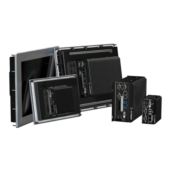
4 | System configuration STOBER System configuration The MC6 motion controller is the perfect choice for reliable coordination of the motion and function sequence in a growing number of applications, in processes with high function complexity and even for very demanding applications. -
Page 15: Hardware Components
Serial number Input voltage 9 – 32 V Input voltage Power consumption Max. 12 watts Power consumption Protection class IP20 Protection class CODESYS V3.5.9.3 Version of the stored software at delivery Tab. 1: Meaning of the specifications on the MC6 nameplate... -
Page 16: Fig. 5 Mc6D01 Nameplate
Serial number Input voltage 9 – 32 V Input voltage Power consumption Max. 12 watts Power consumption Protection class IP20 Protection class CODESYS V3.5.11.50 Version of the stored software at delivery Tab. 2: Meaning of the specifications on the MC6 nameplate... -
Page 17: Material Version
Another sticker with the MV number and serial number, the type designation of the respective device and a combination of STOBER order number and order item is next to the nameplate. Fig. 6: Sticker with MV number and serial number, type designation as well as order number and order... -
Page 18: Type Designation
4 | System configuration STOBER 4.1.3 Type designation Tab. 4: Example code for the MC6 type designation Code Designation Design Series MotionControl Generation Generation 6 C, D Software version Version of the image Design As control cabinet PC With 15'' touch panel With 8.4'' touch panel... -
Page 19: Fig. 7 Graphic Type Overview
STOBER 4 | System configuration 4.1.3.1 Graphic representation of type overview The following graphic provides you with a visual representation of part of the type designation. Fig. 7: Graphic type overview Software version Design Hardware version... -
Page 20: Mc6 Versions
§ SoftMotion CNC/Robotics § Target Visu + Web Visu MC6C15CA 56567 MC6 Core i3 dual-core motion controller (HW 5) with 15" touch panel and software version 3.5.6.40: § SoftMotion CNC/Robotics § Target Visu + Web Visu Tab. 6: MC6, software variant C... -
Page 21: Tab. 7 Mc6, Software Version D, Control Cabinet Pc
STOBER 4 | System configuration Type Description MC6D01NT MC6 Atom dual-core motion controller (HW 1) with software version 3.5.11.50: § Control § Target Visu MC6D01ST MC6 Atom dual-core motion controller (HW 1) with software version 3.5.11.50: § Control + SoftMotion §... -
Page 22: Tab. 8 Mc6, Software Version D, 8.4'' Touch Panel
4 | System configuration STOBER Type Description MC6D21NT MC6 Atom dual-core motion controller (HW 1) with software version 3.5.11.50: § Control § Target Visu MC6D21ST MC6 Atom dual-core motion controller (HW 1) with software version 3.5.11.50: § Control + SoftMotion §... -
Page 23: Tab. 9 Mc6, Software Version D, 15'' Touch Panel
STOBER 4 | System configuration Type Description MC6D11NT MC6 Atom dual-core motion controller (HW 1) with software version 3.5.11.50: § Control § Target Visu MC6D11ST MC6 Atom dual-core motion controller (HW 1) with software version 3.5.11.50: § Control + SoftMotion §... -
Page 24: Software Components
Control (N) license The Control license (N option) is a basic license that is included in the scope of delivery of the MC6 motion controller as standard. It enables flexible programming in accordance with IEC 61131-3 and supports the following languages: §... -
Page 25: Visu Software Option
You can combine the following STOBER drive controllers with the MC6 controller: § SI6 drive controllers § SC6 drive controllers § SD6 drive controllers Note that the axis switcher is not available during operation of a SD6 together with an MC6 motion controller. -
Page 26: Technical Data
5 | Technical data STOBER Technical data Technical data for the MC6 motion controller can be found in the following chapters. Device features Feature MC6, hardware version 1 § Intel Atom Dual-Core E3825, 2 × 1.33 GHz Processor § L2 cache, 1 MB §... -
Page 27: Tab. 11 Device Features For Mc6, Hardware Version 5, Core I3 Dual-Core
(note the functional differences between the software licenses) § Windows Embedded 7 operating system § Real-time clock with battery backup (internal watchdog) Tab. 11: Device features for MC6, hardware version 5, core i3 Dual-Core Feature Version with 8.4'' touch panel § 8.4'' (21.336 cm) SVGA LCD Display §... -
Page 28: Weight
Resistive 4-wire touch panel Touch panel § IP65 protection class Tab. 13: Additional device features for design with 15'' touch panel Weight Type Total weight [kg] MC6x01 MC6x11 MC6x05 1.95 MC6x15 5.95 MC6x21 1.78 Tab. 14: Total weight of the individual MC6 variants... -
Page 29: Dimensions
STOBER 5 | Technical data Dimensions Fig. 8: MC6x01 dimensions, hardware version 1 as control cabinet PC Fig. 9: MC6x11 dimensions, hardware version 1 with 15'' touch panel 256,4 Fig. 10: MC6x21 dimensions, hardware version 1 with 8.4'' touch panel... -
Page 30: Fig. 11 Mc6X05 Dimensions, Hardware Version 5 As Control Cabinet Pc
STOBER Fig. 11: MC6x05 dimensions, hardware version 5 as control cabinet PC Fig. 12: MC6x15 dimensions, hardware version 5 with 15'' touch panel Type Height [mm] Width [mm] Depth [mm] MC6x01 MC6x11 MC6x21 189.4 256.4 MC6x05 MC6x15 Tab. 15: MC6 dimensions [mm]... -
Page 31: Transport, Storage And Operating Conditions
▪ Operate the device within the specified operating conditions. ▪ Make sure the ventilation openings are not covered. Storage and operating conditions Operating temperature 0 – 45 °C Storage temperature –20 – 75 °C Relative humidity 0 – 80%, non-thawing Tab. 16: MC6 storage and operating conditions... -
Page 32: Installation
▪ Mount the MC6 so that the ventilation openings are at the top and bottom and the heat sink ribs are aligned vertically. If this installation position is not possible, be sure to provide adequate ventilation. -
Page 33: Fig. 15 Installation Positions For Mc6X11, Hardware Version 1 With 15'' Touch Panel
STOBER 6 | Installation Fig. 15: Installation positions for MC6x11, hardware version 1 with 15'' touch panel Fig. 16: Installation positions for MC6x21, hardware version 1 with 8'' touch panel Fig. 17: Installation positions for MC6x15, hardware version 5 with 15'' touch panel... -
Page 34: Drilling Diagram: Control Cabinet Pc Variant
6 | Installation STOBER Drilling diagram: control cabinet PC variant MC6x01 The MC6x01 motion controller is mounted on a rail in accordance with DIN EN 60715 TH35. Fig. 18: Top-hat rail mounting of a MC6x01 MC6x05 Due to its size, the MC6x05 motion controller is not suitable for top-hat rail mounting. -
Page 35: Drilling Diagram: 15'' Touch Panel Variant
STOBER 6 | Installation Drilling diagram: 15'' touch panel variant When installing the touch panel, observe the following procedure: First, drill the holes as shown in the drilling diagram. The drilling diagram is valid for all 15'' touch panel variants. -
Page 36: Drilling Diagram: 8.4'' Touch Panel Variant
6 | Installation STOBER Drilling diagram: 8.4'' touch panel variant When installing the touch panel, observe the following procedure: First, drill the holes as shown in the drilling diagram. The drilling diagram is valid for all 8.4'' touch panel variants. -
Page 37: Connection
STOBER 7 | Connection Connection For detailed information about the terminals of the MC6 motion controller and the correct connection, refer to the following chapters. Note that connection work is permitted only when the device is de-energized. Overview: Hardware version 1... -
Page 38: Overview: Hardware Version 5
7 | Connection STOBER Overview: Hardware version 5 Serial 1 Ethernet 24 V CAN 1 CAN 2 CAN 1 / Serial 2 CAN 2 CFast Fig. 23: Connection overview using the example of the MC6x05 Serial 1 Power LED / reset button 2 ×... -
Page 39: Supply
STOBER 7 | Connection 24 V supply ATTENTION! Device damage due to overload! The device may be damaged by a current that is too high. ▪ Make sure that the current over the 24 V power supply terminals does not exceed the value of 2 A. -
Page 40: Canopen
CAN high wire — — External power supply Tab. 19: Connection description for CANopen interface on the MC6 Ethernet Interface 0: Ethernet At this interface, establish the connection to the programming PC or other TCP/IP network nodes in the system. -
Page 41: Commissioning
STOBER 8 | Commissioning Commissioning You would like to operate multiple STOBER drive controllers with the MC6 motion controller using a fieldbus. We are using the following system environment as an example to describe the individual commissioning steps as clearly as possible: §... -
Page 42: Ds6: Configuring The Drive Controller
8 | Commissioning STOBER DS6: Configuring the drive controller Project and configure all drive controllers for your drive system in DS6 DriveControlSuite (also see the chapter DS6: Structure of the program interfaces [} 10]). Information Always perform the steps included in the following chapters in the specified order! 8.1.1... -
Page 43: Parameterizing General Ethercat Settings
Description: If necessary, specify supporting additional information such as the change history of the project configuration. Application tab: If you are working with the MC6 motion controller and the AS6 development environment, we recommend CiA 402 HiRes Motion (version with user-defined units of measure). -
Page 44: Configuring Pdo Transmission
One channel is reserved for FSoE communication and is parameterized automatically. In order to guarantee error-free communication between the controller and drive controller, STOBER offers an application-dependent pre-assignment of the channels which can be changed at any time. -
Page 45: Mapping The Mechanical Drive Model
When scaling the axis, follow the instructions for the application you are projecting. 8.1.4.1 Parameterizing a STOBER standard motor You have projected a STOBER synchronous servo motor with EnDat encoder and integrated holding brake. By projecting the corresponding motor, limit values for currents and torques as well as associated temperature data are automatically transferred to the respective parameters of the individual wizards. - Page 46 8 | Commissioning STOBER 8.1.4.3 CiA 402 HiRes Motion: Scaling an axis ü You have projected the HiRes version of the CiA 402 application. Scale the axis as described below and specify only the number of decimal places in the controller software, i.e.
- Page 47 STOBER 8 | Commissioning 8.1.4.5 Limiting the axis The tasks of a controller include setting axis limits and monitoring them. The reference values necessary for this are parameterized in the controller and transmitted to the individual drive controllers. Note that, for this reason, the reference values of the controller are not negatively affected by the individually configured values on the drive controller side.
-
Page 48: Synchronizing Ethercat Nodes
8 | Commissioning STOBER 8.1.5 Synchronizing EtherCAT nodes Precise synchronization of the EtherCAT nodes is absolutely required for spatially distributed processes that require simultaneous actions (path interpolation). EtherCAT provides the distributed clocks (DC-Sync) method for this. Synchronization using distributed clocks is more precise when compared to the SyncManager event synchronization (SM-Sync) because it is subject to fewer fluctuations. - Page 49 STOBER 8 | Commissioning Saving a project configuration 1. Highlight the drive controllers which have been sent the project configuration in the project tree and click on the first projected axis in the project menu > Wizard area. 2. Select the Save values wizard >...
-
Page 50: As6: Putting The Ethercat System Into Operation
> Project. ð The New Project dialog box opens. 3. Select the standard MC6 project that corresponds to your hardware version. Give it a name and save it wherever you want. ð AutomationControlSuite opens and the Devices view is active. -
Page 51: Configuring Synchronization Using Distributed Clocks
STOBER 8 | Commissioning 8.2.3 Configuring synchronization using distributed clocks ü As the more precise of the two sync methods, synchronization using distributed clocks (DC- Sync) is pre-configured in the EtherCAT master. In order to reduce jitter in general, we recommend setting data transmission (I/O) of the controller to task begin in the EtherCAT configuration. -
Page 52: Parameterizing A Softmotion Axis
8 | Commissioning STOBER 8.2.4 Parameterizing a SoftMotion axis ü You have selected the CiA 402 HiRes Motion application and fully configured the associated axis model in DriveControlSuite. 1. In the device tree, navigate to the first SoftMotion axis SM_Drive_ETC_STOEBER_SI6_HiRes of the first added SI6 or SC6 drive controller and double click to open it. -
Page 53: Configuring Eoe Communication
PC manually to connect the Ethernet and EtherCAT networks (see the chapter EoE: Application cases with STOBER devices). If you are working with a STOBER motion controller and the AS6 development environment, IP routing is activated in the MC6 motion controller by default. -
Page 54: Identifying A Mc6 Motion Controller
Select Device dialog box opens. Select the network path to the controller: Identify the MC6 motion controller by its device name, highlight it and confirm with OK. ð The selected MC6 motion controller is active. 8.2.7 Transmitting a project configuration Transfer the entire project configuration to the motion controller. -
Page 55: Checking The Functionality Of The Axes
6. Click on Insert. ð The Select Item from Object Directory dialog box opens. The directory contains a selection of available CiA objects (along with the coordinates and the name of the corresponding drive controller parameter from STOBER). - Page 56 8 | Commissioning STOBER 7. Highlight the CiA object for which you would like to extend PDO transmission and confirm with OK. If the desired CiA object is not included in the directory, enter its index and subindex in the corresponding fields (if necessary, calculate both indices as described in the chapters Manufacturer-specific parameters: 2000 hex –...
-
Page 57: System Maintenance And Diagnostics
USB dongle. This has multiple advantages: With series machines, an MC6 can also be backed up on an MC6 of the same design. This enables you to shorten the commissioning time significantly. This is also true in case of service: you can use the back-up image not only on the exact same device, but also on any MC6 of the same design. -
Page 58: Diagnostics
9 | System maintenance and diagnostics STOBER Diagnostics LEDs on the front give you initial information about the state of the respective device as well as the states of the physical connection and the communication. 9.3.1 Hardware version 1 The MC6x1 motion controller has three status LEDs with different functions. -
Page 59: More About Mc6 And As6
Important information about the MC6 10.1.1 Status LEDs You can activate the S0 and S1 LEDs of the MC6 in order to display user-defined system statuses. To do so, you need the device description file STOEBER_MC6_LEDS.devdesc.xml. The MC6xx5 version does not support this function. -
Page 60: Measures For Data Security
First shut down, then switch off If the MC6 motion controller is switched off while the software is writing a file to the CFast memory device, this file will be damaged in most cases. -
Page 61: Dual-Use Item
File system check On the MC6 motion controller, the CODESYS runtime environment is not started by the conventional autostart mechanism of the operating system. Instead, it is started by a batch script, the last command of which initiates the start of the runtime environment. -
Page 62: Important Information About The As6
With the HiRes Motion version, the interface for the controller is specifically tailored to the HiRes MC6 device driver, meaning that reference and actual values are displayed and transmitted in units that can be individually defined by the user. - Page 63 STOBER 10 | More about MC6 and AS6? 10.2.1.1 Settings in AutomationControlSuite If you have chosen a HiRes driver, you only need to enter the number of decimal places for the position value in AutomationControlSuite. The axis model is completely parameterized in the drive.
-
Page 64: Synchronization
10 | More about MC6 and AS6? STOBER 10.2.2 Synchronization For spatially distributed processes that require simultaneous actions, the EtherCAT master and slaves absolutely must work in synchronization with each other in the same cycle. EtherCAT provides two different methods for synchronizing the master and slaves: a SyncManager event (SM-Sync) and distributed clocks (DC-Sync). -
Page 65: Fig. 25 Ethercat - Distributed Clocks
STOBER 10 | More about MC6 and AS6? 10.2.2.2 DC-Sync: Synchronization using distributed clocks Synchronization using the distributed clocks method allows the same time to be maintained for all nodes of an EtherCAT network. Each EtherCAT slave with distributed clocks functionality has a local distributed clock. Normally, the time from the first DC-Sync-capable EtherCAT slave downstream of the master in the network serves as the reference time. -
Page 66: Fig. 26 Dc-Sync - Shift Times
Sync0 signal of the slaves for the entire network simultaneously. Master Shift Time is parameterized on the master's end. Master Shift Time is referred to as Sync Offset in STOBER AS6 AutomationControlSuite and as Sync Shift Time in Beckhoff TwinCAT. - Page 67 STOBER 10 | More about MC6 and AS6? § PLL phase offset ... Specifies the time span between the Sync0 signal and the start of process data processing by the slave. PLL phase offset is parameterized on the slave's end, i.e. in the drive controller in parameter A292.
- Page 68 10 | More about MC6 and AS6? STOBER 4. Bit 2: A150 lengthened If the associated LED lights up, the cycle time parameterized in A150 of the drive controller is lengthened. 5. Bit 3: Maximum control range reached If the associated LED lights up, check whether the cycle times of the master and drive controller agree.
-
Page 69: Persistent Variables
Alarms such as faults or messages are automatically saved in non-volatile storage on drive D of the MC6 by the Alarm Manager. The Persistence Manager or the NOVRAM of the MC6 are available as non-volatile data memory in order to save running-time meters, part counters or other data. -
Page 70: Softmotion Encoder
Manager to TRUE. NOVRAM Storage of data is also easy to handle in the NOVRAM of the MC6. However, the size is limited to a maximum of 128 kB. The memory capacity being used is displayed during the transfer to the controller. -
Page 71: Establishing A Connection
10.2.5.1 IP address and subnet mask The MC6 motion controller is factory-set to DHCP server at network jack 0. If a DHCP server cannot be found on the network, after some time, the device switches to the alternative network setting with the following, fixed IP address: §... - Page 72 The connection is password-protected. The password is: stoeber. Change this preset password to prevent a security gap in the system. Information Note that you can use the name as well as the existing IP address of the MC6 to establish the connection. Information This connection cannot be used as-is for remote maintenance.
-
Page 73: Changes To The File System
If "Commit and Restart" is not used, all changes will be lost after a restart. This does not apply to user programs that are written to the MC6 using AutomationControlSuite. The batch files needed for "Commit and Restart" are located on the desktop of the MC6 in the "Batch Files" folder. -
Page 74: Safety-Related Applications
Device description files are already included in the scope of delivery of the AS6. If you want to use an MC6 that is not included in the device repository of the AS6, you can download a corresponding package from the STOBER Download Center. Click the following link http://www.stoeber.de/en/download... -
Page 75: As6: Example Projects
STOBER 10 | More about MC6 and AS6? 10.2.9 AS6: example projects The AS6 AutomationControlSuite development environment provides you with the following example projects: Drive & Motion ActiveX Includes how to handle an ActiveX element in the visualization Drive & Motion CNC 5-axis template Includes how to handle CNC G-code and activate 5-axis kinematics Drive &... -
Page 76: Appendix
11 | Appendix STOBER Appendix 11.1 Detailed information The documentation listed in the following table offers additional relevant information about the associated drive controllers. Current document versions can be found at http://www.stoeber.de/en/download. Device/Software Documentation Contents SC6 drive controller Manual System setup, technical data, project... -
Page 77: Abbreviations
STOBER 11 | Appendix 11.2 Abbreviations Abbreviation Meaning CAN in Automation Digital Visual Interface Ethernet over EtherCAT EtherCAT Ethernet for Control Automation Technology Ground Human Machine Interface Input/Output Internet Protocol Open Platform Communications Process Data Objects Received data RxPDO Received PDO... -
Page 78: Contact
Your suggestions, opinions, wishes and constructive criticism help us to ensure and further develop the quality of our documentation. If you want to contact us for a specific reason, we would be happy to receive an e-mail from you documentation@stoeber.de Thank you for your interest. Your STOBER editorial team... -
Page 79: Close To Customers Around The World
STOBER 12 | Contact 12.3 Close to customers around the world We offer you committed, expert advise and support in over 40 countries worldwide: STOBER AUSTRIA STOBER SOUTH EAST ASIA www.stoeber.at www.stober.sg Phone +43 7613 7600-0 sales@stober.sg sales@stoeber.at STOBER CHINA STOBER SWITZERLAND www.stoeber.cn... - Page 80 List of figures Fig. 1 AS6 – Program interface ..................Fig. 2 DriveControlSuite – Program interface ..............Fig. 3 System overview for the MC6 with SI6 and PS6 ............ Fig. 4 MC6C01CT nameplate ................... Fig. 5 MC6D01 nameplate....................Fig. 6 Sticker with MV number and serial number, type designation as well as order number and order item ...................
- Page 81 MC6, software version D, 15'' touch panel ............. Tab. 10 Device features for MC6, hardware version 1, Atom Dual-Core......Tab. 11 Device features for MC6, hardware version 5, core i3 Dual-Core ......Tab. 12 Additional device features for design with 8.4'' touch panel ........Tab. 13 Additional device features for design with 15'' touch panel ........
- Page 82 Technische Änderungen vorbehalten. Errors and changes excepted. ID 442461.04 05/2018 STÖBER ANTRIEBSTECHNIK GmbH + Co. KG Kieselbronner Str. 12 75177 Pforzheim Germany Tel. +49 7231 582-0 mail@stoeber.de www.stober.com Service-Hotline +49 7231 582-3000...
Need help?
Do you have a question about the MC6 and is the answer not in the manual?
Questions and answers