Stober SD6 Manual
Drive controller
Hide thumbs
Also See for SD6:
- Manual (439 pages) ,
- Commissioning instructions (166 pages) ,
- Operating manual (93 pages)
Table of Contents
Advertisement
Quick Links
Advertisement
Chapters
Table of Contents

Subscribe to Our Youtube Channel
Related Manuals for Stober SD6


Summary of Contents for Stober SD6
- Page 1 SD6 drive controller Manual stober.com en-US 04/2018 ID 442426.07...
-
Page 2: Table Of Contents
Table of contents STOBER Table of contents Foreword .......................... 9 User information........................ 10 Storage and transfer .................... 10 Described product type.................... 10 Timeliness........................ 10 Original language...................... 10 Limitation of liability..................... 10 Formatting conventions .................... 11 2.6.1 Use of symbols ..................... 11 2.6.2... - Page 3 Derating ...................... 47 6.1.4 Dimensions.................... 49 6.1.5 Weight ...................... 52 DC link connection...................... 52 6.2.1 General technical data.................. 52 6.2.2 DL6A – SD6 assignment ................ 53 6.2.3 Dimensions.................... 54 6.2.4 Weight ...................... 55 Safety technology ....................... 55 6.3.1 ST6 ....................... 55 6.3.2 SE6.......................
- Page 4 Table of contents STOBER DC link connection...................... 98 7.2.1 Information on design and operation ............ 99 7.2.2 Design ...................... 100 Mixed operation ...................... 102 Storage .......................... 104 Drive controller...................... 104 8.1.1 Annual reforming .................. 105 8.1.2 Reforming before commissioning ............... 106 Installation........................
- Page 5 12.1.3 Creating other modules and drive controllers.......... 242 12.1.4 Specifying a module ................... 242 12.1.5 Specifying the project ................. 242 12.2 Mechanical drive model .................... 243 12.2.1 Parameterizing the STOBER motor ............ 243 12.2.2 Parameterizing the axis model .............. 243...
- Page 6 Table of contents STOBER 12.3 Testing the project configuration................ 246 12.3.1 Test using DriveControlSuite.............. 246 12.3.2 Test using the operating unit of the drive controller........ 249 13 Communication ....................... 251 13.1 System requirements.................... 251 13.1.1 Personal firewall .................. 251 13.1.2 Protocols and ports for communication using routers ........ 252 13.1.3 IGB and IGB motion bus network ...............
- Page 7 15.3 Replacing the drive controller ................... 317 15.4 Replacing or updating the firmware ................ 319 16 Service.......................... 320 16.1 STOBER electronics service .................. 320 16.2 Creating reverse documentation................ 321 16.2.1 Drive controller without SE6 option ............ 321 16.2.2 Drive controller with SE6 option .............. 322 17 Appendix ..........................
- Page 8 Table of contents STOBER 17.1.5 BFL 5.08HC 180 SN................... 330 17.1.6 BLDF 5.08 180 SN .................. 331 17.1.7 DFMC 1.5 -ST-3.5 .................. 332 17.1.8 GFKC 2,5 -ST-7,62.................. 333 17.1.9 GFKIC 2.5 -ST-7.62.................. 334 17.1.10 SPC 5 -ST-7,62 .................. 335 17.1.11 ISPC 5 -STGCL-7,62.................. 336 17.1.12 SPC 16 -ST-10,16 ..................
-
Page 9: Foreword
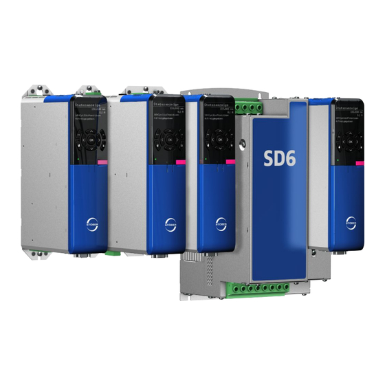
There is also an option of connecting the drive controllers in a DC intermediate circuit for multi-axis applications, which improves the energy footprint of the entire system. The SD6 drive controller is available in four sizes with a nominal output current of up to 85 A. -
Page 10: User Information
2 | User information STOBER User information This documentation covers the SD6 drive controller. You will receive support for the assembly of the individual modules along with the associated components that you will need to operate the drive controllers in the control cabinet. -
Page 11: Formatting Conventions
STOBER 2 | User information Formatting conventions Orientation guides in the form of signal words, symbols and special text markups are used to emphasize specific information so that you are able identify it in this documentation quickly. 2.6.1 Use of symbols Safety instructions are identified with the following symbols. -
Page 12: Markup Of Text Elements
2 | User information STOBER 2.6.2 Markup of text elements Certain elements of the continuous text are distinguished as follows. Quick DC-Link module Words or expressions with a special meaning Detailed information Internal cross-reference http://www.stoeber.de External cross-reference Software and display indicators The following formatting is used to identify the various information content of elements referenced by the software interface or the drive controller display, as well as any user entries. -
Page 13: Symbols, Marks And Test Symbols
STOBER 2 | User information Symbols, marks and test symbols EN 61558-2-20 Choke without overload protection. Grounding symbol Grounding symbol in accordance with IEC 60417-5019 (DB:2002-10). RoHS lead-free mark Marking in accordance with RoHS directive 2011-65-EU. CE mark Manufacturer's self declaration: The product meets the requirements of EU directives. -
Page 14: Trademarks
Products that are registered as trademarks are not specially indicated in this documentation. Existing property rights (patents, trademarks, protection of utility models) are to be observed. Licenses Software from the following licensor is used in SD6: SEGGER Microcontroller GmbH & Co. KG In den Weiden 11... -
Page 15: General Safety Instructions
STOBER 3 | General safety instructions General safety instructions There are risks associated with the product described in this documentation that can be prevented by complying with the described warning and safety instructions as well as the included technical rules and regulations. -
Page 16: Intended Use
EMC-compliant installation The SD6 drive controller and accessories must be installed and wired compliant for EMC Modification As the user, you may not make any physical, technical or electrical modifications to the SD6 drive controller and the accessories. Maintenance The SD6 drive controller and accessories do not require maintenance. For the safety module, take appropriate measures to detect or prevent possible errors in the connection wiring. -
Page 17: Working On The Machine
Use in potentially explosive atmospheres § Use in environments with harmful substances as specified by EN 60721, such as oils, acids, gases, vapors, dust and radiation Implementation of the following applications is permitted only after approval from STOBER: § Use in non-stationary applications §... -
Page 18: Ul-Compliant Use
(peak permitted rated surge voltage = 6 kV) Motor protection All models of the 6th STOBER drive controller generation feature a certified i²t model, a computational model for thermal monitoring of the motor. This fulfills the requirements for solid state motor overload protection in accordance with the amendment to UL 508C from May 2013. - Page 19 The integral solid state short circuit protection does not provide branch circuit protection. If you would like to branch the output of the drive controller, branch circuit protection must be ensured in coordination with STOBER and in compliance with the National Electrical Code as well as all additional applicable local regulations or equivalent provisions.
-
Page 20: System Configuration
402 interface. You commission the drive controller using the DriveControlSuite software. You can also connect multiple SD6 drive controllers in an intermediate circuit and thus improve the energy footprint of the entire system. For this purpose, you will need an appropriate Quick DC-Link module for each drive controller. -
Page 21: Hardware Components
Below you will find an overview of the available hardware components. 5.1.1 Drive controller The SD6 drive controller is available in multiple sizes. Various interface options can also be selected. The type specifications used in this documentation refer to the nameplate located on the side of the drive controller. -
Page 22: Fig. 3 Sticker With Mv And Serial Number
Output current for 8 kHz clock frequency Protection class IP20 Protection class Tab. 2: Meaning of the specifications on the SD6 nameplate Information UL and cUL certified devices with the corresponding test symbol meet the requirements of standards UL 508C and UL 840. -
Page 23: Tab. 4 Sample Code
STOBER 5 | System configuration 5.1.1.3 Type designation Tab. 4: Sample code Code Designation Design Series ServoDrive Generation Generation 6 A, B Version – 3 Size (0 – 9) Power output stage Power output stage within the size Safety module... -
Page 24: Tab. 6 Available Sd6 Types And Sizes
SD6 in sizes 0, 1, 2 and 3 5.1.2 Controller The development of the MC6 motion controller and its integration into the STOBER product portfolio opens up new solutions for drive technology, especially for complex functions with demanding requirements for timing and precision. -
Page 25: Operating Motors, Encoders And Brakes
The LA6A adapter box allows sensor signals from various linear motor types to connect to SD6. In the process, the adapter box is responsible for splitting the various sensor signals, which, depending on the motor type, are sometimes collected at a terminal, as well as the level adjustment of the hall signals. -
Page 26: Accessories
5 | System configuration STOBER 5.1.4 Accessories You can find information about the available accessories in the following chapters. 5.1.4.1 Safety technology The safety modules are used to realize the STO safety function. They prevent the generation of a rotating magnetic field in the power unit of the drive controller. For an external requirement or in the event of error, the safety module switches the drive controller to the STO state. - Page 27 [} 344]. 5.1.4.2 Communication The SD6 drive controller has two interfaces for IGB communication on the top of the device as standard. The communication module is installed in the shaft at the top and it is used to connect the drive controller to the fieldbus system.
- Page 28 5 | System configuration STOBER EC6 communication module ID No. 138425 Communication module for the EtherCAT connection. EtherCAT cables Ethernet patch cable, CAT5e, yellow. The following designs are available: ID No. 49313: Length approx. 0.2 m. ID No. 49314: length approx. 0.35 m.
- Page 29 STOBER 5 | System configuration PN6 communication module ID No. 56426 Communication module for the PROFINET connection. Detailed information about the fieldbus connection can be found in the corresponding manual, see chapter Detailed information [} 344]. 5.1.4.3 Terminal module XI6 terminal module ID no.
- Page 30 TTL pulse train, single-ended (evaluation) § HTL pulse train, single-ended (simulation and evaluation) Please note: For connecting STOBER resolver cables with 9-pin D-sub connectors, you also require the AP6A00 interface adapter, available separately (ID No. 56498, D-sub 9-pin to 15-pin).
- Page 31 STOBER 5 | System configuration AP6 interface adapters Adapter for connecting resolver cables with 9-pin D-sub connectors to the X140 encoder interface of the RI6 terminal module. The following designs are available: AP6A00 ID No. 56498 Adapter X140 resolver, 9/15-pin.
- Page 32 5.1.4.4 DC link connection If you want to connect SD6 drive controllers into the DC link group, you will need the Quick DC- Link module of type DL6A. You receive the DL6A rear section modules in different designs for a horizontal connection, suitable for the size of the drive controller.
- Page 33 More detailed information can be found in the chapter Technical data. 5.1.4.6 Choke STOBER offers different chokes corresponding to your application. More detailed information can be found in the chapter Technical data. 5.1.4.7 EMC shroud You can use the EM6A EMC shroud to connect the cable shield of the power cable.
- Page 34 X120 SSI/TTL connection cable ID No. 49482 Cable for connecting the X120 TTL interface on the SD6 drive controller (on terminal module RI6 or XI6) with the X301 interface on the LA6 adapter box in order to transfer Hall sensor signals.
- Page 35 STOBER 5 | System configuration 5.1.4.9 Battery module Absolute Encoder Support (AES) ID No. 55452 Battery module for buffering the power supply when using an inductive EnDat 2.2 digital absolute encoder with battery-buffered multi-turn stage, for example EBI1135 or EBI135.
-
Page 36: Software Components
5.2.2 Applications Drive-based motion control is recommended for the decentralized motion control of sophisticated machines. The drive-based application package from STOBER is the right choice wherever universal and flexible solutions are needed. In the STOBER Drive Based synchronous application, the PLCopen Motion Control command set provides drive-based motion control for synchronous run, positioning, velocity and torque/force. -
Page 37: Technical Data
STOBER 6 | Technical data Technical data Technical data for the drive controllers and accessories can be found in the following chapters. Drive controllers The following chapters contain specifications for the electrical data, dimensions and weight of the drive controller. -
Page 38: Electrical Data
Tab. 10: Discharge times of the DC link circuit 6.1.2 Electrical data The electrical data of the available SD6 sizes as well as the properties of the brake chopper can be found in the following sections. Information For the time span between two energizing processes, note that: a) Direct, repeat activation of the supply voltage is possible for power-on/power-off operation. -
Page 39: Tab. 12: Sd6 Electrical Data, Size 0
PWM,PU 8,3 A 2,8 A 5,4 A 1N,PU 4 A 2,3 A 4,5 A 2N,PU 180% for 5 s; 150% for 30 s 2maxPU Tab. 13: SD6 electrical data, size 0, for 4 kHz clock frequency Electrical data SD6A02 SD6A04 SD6A06 8 kHz PWM,PU 6 A 2,2 A 4 A 1N,PU 3 A 1,7 A... -
Page 40: Tab. 16 Sd6 Electrical Data, Size 1
SD6A16 4 kHz PWM,PU 12 A 19,2 A 1N,PU 10 A 16 A 2N,PU 180% for 5 s; 150% for 30 s 2maxPU Tab. 17: SD6 electrical data, size 1, for 4 kHz clock frequency Electrical data SD6A14 SD6A16 8 kHz PWM,PU 9,3 A 15,8 A 1N,PU 6 A 10 A 2N,PU 250% for 2 s;... -
Page 41: Tab. 20: Sd6 Electrical Data, Size 2
SD6A26 4 kHz PWM,PU 26,4 A 38,4 A 1N,PU 22 A 32 A 2N,PU 180% for 5 s; 150% for 30 s 2maxPU Tab. 21: SD6 electrical data, size 2, for 4 kHz clock frequency Electrical data SD6A24 SD6A26 8 kHz PWM,PU 24,5 A 32,6 A 1N,PU 14 A 20 A 2N,PU 250% for 2 s;... -
Page 42: Tab. 24: Sd6 Electrical Data, Size 3
PWM,PU 45,3 A 76 A 76 A 1N,PU 44 A 70 A 85 A 2N,PU 180% for 5 s; 150% for 30 s 2maxPU Tab. 25: SD6 electrical data, size 3, for 4 kHz clock frequency Electrical data SD6A34 SD6A36 SD6A38 8 kHz PWM,PU 37 A 62 A 76 A 1N,PU 30 A 50 A... -
Page 43: Tab. 27: Brake Chopper Electrical Data, Size 3
STOBER 6 | Technical data Electrical data SD6A34 SD6A36 SD6A38 780 – 800 V onCH 740 – 760 V offCH 30 Ω (PTC resistance; 100 W; max. 1 kW for 1 s; τ = 40 s) intRB 15 Ω 2minRB 42 kW maxRB 19.4 kW effRB Tab. 27: Brake chopper electrical data, size 3... - Page 44 6 | Technical data STOBER 6.1.2.8 Power loss data in accordance with EN 50598 Type Nominal Apparent Absolute Operating points Compari current power losses class 2N,PU V,CU (0/25) (0/50) (0/100) (50/25) (50/50) (50/100) (90/50) (90/100) Relative losses [kVA] SD6A02 5.01 5.07...
-
Page 45: Tab. 29 Power Loss Data Of The Sd6 Drive Controller In Accordance With En 50598
554.6 1143.1 35.3 Tab. 29: Power loss data of the SD6 drive controller in accordance with EN 50598 General conditions The loss data applies to drive controllers without any accessories. The power loss calculation is based on a three-phase supply voltage with 400 V /50 Hz. -
Page 46: Tab. 30 Absolute Losses In The Accessories
6 | Technical data STOBER 6.1.2.9 Power loss data of accessories If you intend to order the drive controller with accessory parts, losses increase as follows: Type Absolute losses ST6 safety module IO6 terminal module < 2 XI6 terminal module <... -
Page 47: Derating
STOBER 6 | Technical data 6.1.3 Derating When dimensioning the drive controller, observe the derating of the nominal output current as a function of the clock frequency, surrounding temperature and installation altitude. There is no restriction for a surrounding temperature from 0 °C to 45 °C and an installation altitude of 0 m to 1000 m. - Page 48 6 | Technical data STOBER 6.1.3.2 Effect of the surrounding temperature Derating as a function of the surrounding temperature is determined as follows: § 0 °C to 45 °C: No restrictions (D = 100%) § 45 °C to 55 °C: Derating −2.5%/K Example The drive controller needs to be operated at 50 °C.
-
Page 49: Dimensions
STOBER 6 | Technical data 6.1.4 Dimensions The dimensions of the available SD6 sizes can be found in the following sections. 6.1.4.1 Dimensions: sizes 0 to 2 Fig. 4: SD6 dimensional drawing, sizes 0 to 2 Dimension Size 0 Size 1... -
Page 50: Fig. 5: Sd6 Dimensional Drawing, Size 3
6 | Technical data STOBER 6.1.4.2 Dimensions: size 3 Fig. 5: SD6 dimensional drawing, size 3... -
Page 51: Tab. 33 Sd6 Dimensions, Size 3 [Mm]
Fastening holes Vertical distance 365+2 Vertical distance to the 11.5 upper edge Horizontal distance 150+0.2/−0.2 between the fastening holes of the drive controller Horizontal distance to the side edge of the drive controller Tab. 33: SD6 dimensions, size 3 [mm]... -
Page 52: Weight
5470 Size 2 5050 6490 Size 3 13300 14800 Tab. 34: Weight of SD6 [g] If you intend to order the drive controller with accessory parts, the weight increases as follows. Accessories Weight without packaging [g] Communication module Terminal module Safety module Tab. -
Page 53: Dl6A - Sd6 Assignment
— SD6A06 — — — SD6A14 — — — SD6A16 — — — SD6A24 — — — SD6A26 — — — SD6A34 — — — SD6A36 — — — SD6A38 — — — Tab. 39: Assignment of DL6A to SD6... -
Page 54: Dimensions
6 | Technical data STOBER 6.2.3 Dimensions 0 – 2 Fig. 6: DL6A dimensional drawing Dimension DL6A0 DL6A2 DL6A3 DL6A1 Quick DC-Link Width Depth Height Fastening clip height Height incl. fastening clips Fastening holes Vertical distance 283+2 380+2 (wall mounting) Vertical distance to the... -
Page 55: Weight
Tab. 41: DL6A weight [g] Safety technology 6.3.1 The ST6 safety module adds the STO safety function to the SD6 drive controller via terminal X12. Information If you would like to use STO safety function over terminals, be sure to read the ST6 manual;... -
Page 56: Operating Motors
24 V supply 20.4 – 28.8 V Tab. 44: X15 electrical data – Digital outputs (SE6 option) Operating motors You can operate the following motors with the specified control modes on the SD6 drive controller. Motor type B20 Control Encoder Other settings... - Page 57 STOBER 6 | Technical data Motor type B20 Control Encoder Other settings Characteristics mode Asynchronous 2: ASM - vector Encoder — High dynamics, high motor control required accuracy, very constant speed, high overcurrent protection 3: ASM - No encoder —...
-
Page 58: Evaluable Encoders
6 | Technical data STOBER Evaluable encoders The technical data of the evaluable encoder can be found in the following chapters. All encoder connections except connection X50 can be used as position or master encoders. The use as a motor encoder depends on which encoder design is required by your motor and supported by the encoder connection. - Page 59 STOBER 6 | Technical data Encoders Connection Connection location Note HTL pulse and X101 IO6, XI6 or RI6 HTL signals, single-ended; direction terminal modules evaluation and simulation TTL pulse and X101 RI6 terminal module TTL signals, single-ended direction X120 XI6 or RI6 terminal TTL signals, differential;...
-
Page 60: Signal Transmission
6 | Technical data STOBER 6.5.2 Signal transmission The following signal levels apply to single-ended signal transmission: Signal level HTL, single-ended TTL, single-ended Low level 0 – 8 V 0 – 0.8 V High level 15 – 30 V 2 – 6 V The following signal levels apply for differential signal transmission:... -
Page 61: Tab. 49 Ssi Specification
STOBER 6 | Technical data SSI encoders Specification 5 – 15 V (see encoder supply) 250 mA 2max (sum of X4, X120, X140: 500 mA) 13 mA 2min Encoder type and format Multi-turn: 24 or 25 bits; single-turn: 13-bit short or 13-bit fir tree (13 bits of data in 25... -
Page 62: Tab. 51 Encoder Supply X4
6 | Technical data STOBER Encoder supply Through Note 5 V (regulated at the Sense lead of the encoder STOBER synchronous servo encoder) connected at pin 12 (sense) motors; EnDat 2.1/2.2 encoder (standard) 5 V (regulated at X4) Pin 12 (sense) bridged with... -
Page 63: Terminal Module
STOBER 6 | Technical data Incremental encoders Specification Incremental signals 5 – 30 V 0.2 A 2max — 2min 500 kHz Signal level TTL, differential Max. cable length 50 m, shielded Tab. 53: Specification for incremental signals 6.5.4 Terminal module Depending on the terminal module, the following additional encoder interfaces are available. -
Page 64: Tab. 55 Specification For X101 On Ri6 Terminal Module For Incremental, Pulse/Direction Or Hall Sensor Signals
6 | Technical data STOBER X101 on RI6 terminal module Electrical data Binary inputs/ HTL, single-ended TTL, single-ended outputs (evaluation and simulation) BE1 – BE5 30 V 6 V 1max 16 mA 13 mA 1max BE1 – BE3 10 kHz 10 kHz BE4 – BE5 100 kHz 250 kHz... -
Page 65: Tab. 56 Specification For X101 On Xi6 Terminal Module For Incremental, Pulse/Direction Or Hall Sensor Signals
STOBER 6 | Technical data X101 on XI6 terminal module Electrical data Binary inputs/ HTL, single-ended outputs (evaluation and simulation) BE1 – BE5 30 V 1max 16 mA 1max BE1 – BE3 10 kHz BE4 – BE5 100 kHz (if high level > 15 V... -
Page 66: Tab. 57 Specification For X101 On Io6 Terminal Module For Incremental, Pulse/Direction Or Hall Sensor Signals
6 | Technical data STOBER X101 on IO6 terminal module Electrical data Binary inputs/ HTL, single-ended outputs (evaluation and simulation) BE1 – BE5 30 V 1max 16 mA 1max BE1 – BE3 10 kHz BE4 – BE5 100 kHz (if high level > 15 V... -
Page 67: Tab. 58 Ssi Specification
STOBER 6 | Technical data 6.5.4.2 X120 The X120 encoder connection is part of the optional XI6 and RI6 terminal modules. SSI encoder (evaluation and simulation) Specification 15 V (see encoder supply) 250 mA 2max (sum of X4, X120, X140: 500 mA) Encoder type and format Multi-turn: 24 or 25 bits;... -
Page 68: Tab. 60 X120 Encoder Supply
6 | Technical data STOBER Encoder supply Depending on the power consumption of the encoder, an external supply may be required, which can cause differences in the GND connection. Bridge Internal: Pin 8 (U Pin 1 (GND-ENC) to pin 9 (GND) -
Page 69: Tab. 63 Specification For Resolver Signals
STOBER 6 | Technical data Resolver Specification Resolver signals −10 V to +10 V 80 mA 2max 7 – 9 kHz 0.8 W Transfer ratio 0.5 ± 5 % Number of poles 2, 4 and 6 Signal shape Sinus Max. cable length 100 m, shielded Tab. 63: Specification for resolver signals EnDat 2.1 sin/cos encoder and sin/cos encoder... -
Page 70: Tab. 65 Encoder Supply X140
6 | Technical data STOBER Encoder supply Through Note 5 V (regulated at the Sense lead of the encoder STOBER synchronous servo encoder) connected at pin 12 (sense) motors; EnDat 2.1/2.2 (standard) 5 V (regulated at X140) Pin 12 (sense) bridged with... -
Page 71: Encoder Adapter Box
The connections X300 to X306 are part of the optional LA6 adapter box. LA6 is an interface adapter for differential TTL incremental signals and single-ended TTL hall sensor signals. LA6 transmits TTL signals from synchronous linear motors to the SD6 drive controller. 6.5.5.1 X300 X300 transmits differential TTL incremental signals to connection X4 of the drive controller. -
Page 72: Tab. 68 Single-Ended Htl Hall Sensor Signals Specification
6 | Technical data STOBER 6.5.5.3 X302 X302 converts single-ended TTL hall sensor signals for the transmission to connection X101 on the XI6, RI6 or IO6 terminal module. Single-ended HTL hall sensor Specification Incremental signals Typical voltage drop < 2 V ;... -
Page 73: Terminal Module
STOBER 6 | Technical data Information Calculation example – Limit frequency f for an encoder with 2,048 pulses per revolution: 3,000 revolutions per minute (equivalent to 50 revolutions per second) * 2,048 pulses per revolution = 102,400 pulses per second = 102.4 kHz <<... -
Page 74: Tab. 74 X101 Electrical Data For Binary Signals
6 | Technical data STOBER X101 specification for binary signals Electrical data Binary inputs/ Value outputs Low level BE1 – BE5 0 – 8 V High level 12 – 30 V 30 V 1max 16 mA 1max BA1 – BA2 50 mA 2max Typical voltage drop <... -
Page 75: Ri6
STOBER 6 | Technical data X103B specification Electrical data Binary inputs/ Value outputs Low level 0 – 8 V High level 12 – 30 V 30 V 1max 16 mA 1max BA7 – BA10 50 mA 2max Typical voltage drop < 2 V Tab. 77: X103B electrical data... -
Page 76: Tab. 80 X100 Electrical Data
6 | Technical data STOBER X100 specification Electrical data Analog input/ Value output Level AE1 – AE2 ±10 V Resolution 16 bits Internal resistance > 40 kΩ Level AE1 as current ±20 mA input (AE1+ and Resolution 16 bits AE1 shunt bridged) Internal resistance 492 Ω... -
Page 77: Io6
STOBER 6 | Technical data 6.6.3 General specification Specification Value Internal device update rate Cycle time for the application parameterized in A150; t = 1 ms; Also applicable for binary inputs BE4 and BE5: with timestamp correction in an accuracy range of 1 µs Max. -
Page 78: Weight
6 | Technical data STOBER X101 specification for binary signals Electrical data Binary inputs/ Value outputs Low level BE1 – BE5 0 – 8 V High level 12 – 30 V 30 V 1max 16 mA 1max BE1 – BE3 10 kHz 1max BE4 – BE5 250 kHz... -
Page 79: Controllable Brakes
STOBER 6 | Technical data Controllable brakes You can control the following brakes: § 24 V brakes connected directly to X5 § Brakes connected indirectly (e.g. over coupling contactor) to X5 Only in combination with SE6 safety module: § 24 V brakes connected directly to X8 §... -
Page 80: Evaluable Motor Temperature Sensors
6 | Technical data STOBER Evaluable motor temperature sensors You can connect a maximum of 2 PTC triplets in a row, one KTY84-130 or one Pt1000 to SD6. Information STOBER recommends the use of PTC thermistors as thermal motor protection. -
Page 81: Fzmu, Fzzmu Tubular Fixed Resistor
SD6A26 (—) SD6A34 (—) (—) SD6A36 (—) (—) SD6A38 (—) (—) Tab. 88: Assignment of FZMU, FZZMU 400×65 braking resistor – SD6 drive controller Recommended Possible (—) Useful under certain conditions — Not possible Properties Specification FZMU 400×65 FZZMU 400×65 ID No. -
Page 82: Fig. 7 Fzmu, Fzzmu 400×65 Dimensional Drawing
6 | Technical data STOBER The internal connections are wired to terminals with heat-resistant, silicone-insulated strands of wire. Also ensure a heat-resistant and stress-resistant design for the connection! Connection type Conductor cross-section [mm²] Rigid 0.5 – 4.0 Flexible with end sleeve 0.5 –... -
Page 83: Gvadu, Gbadu Flat Resistor
(—) (—) (—) SD6A34 (—) (—) (—) (—) SD6A36 (—) (—) (—) (—) SD6A38 (—) (—) (—) (—) Tab. 92: Assignment of GVADU, GBADU braking resistor – SD6 drive controller Recommended Possible (—) Useful under certain conditions — Not possible... -
Page 84: Tab. 93 Gvadu, Gbadu Specification
6 | Technical data STOBER Properties Specification GVADU GBADU GBADU GBADU GBADU 210×20 265×30 405×30 335×30 265×30 ID No. 55441 55442 55499 55443 55444 Type Flat Flat Flat Flat Flat resistor resistor resistor resistor resistor Resistance [Ω] Power [W] Therm. time const. τ... -
Page 85: Fig. 8 Gvadu, Gbadu Dimensional Drawing
STOBER 6 | Technical data Dimensions Dimension GVADU GBADU GBADU GBADU GBADU 210×20 265×30 405×30 335×30 265×30 ID No. 55441 55442 55499 55443 55444 18.2 28.8 28.8 28.8 28.8 10.8 10.8 10.8 10.8 β 65° 73° 73° 73° 73° Tab. 94: GVADU, GBADU dimensions [mm]... -
Page 86: Fgfku Steel-Grid Fixed Resistor
53897 SD6A24 — — — SD6A26 — — — SD6A34 SD6A36 SD6A38 Tab. 95: Assignment of FGFKU braking resistor – SD6 drive controller Recommended Possible (—) Useful under certain conditions — Not possible Properties Specification FGFKU ID No. 55449 55450... -
Page 87: Fig. 9 Fgfku Dimensional Drawing
STOBER 6 | Technical data Dimensions Dimension FGFKU ID No. 55449 55450 55451 53897 Tab. 98: FGFKU dimensions [mm] ø10,5 Drilling pattern Fig. 9: FGFKU dimensional drawing... -
Page 88: Rb 5000 Rear Section Braking Resistor
SD6A24 — — SD6A26 — — SD6A34 — — — SD6A36 — — — SD6A38 — — — Tab. 99: Assignment of RB 5000 braking resistor – SD6 drive controller Recommended Possible (—) Useful under certain conditions — Not possible... -
Page 89: Tab. 100 Rb 5000 Specification
STOBER 6 | Technical data Properties Specification RB 5022 RB 5047 RB 5100 ID No. 45618 44966 44965 Resistance [Ω] Power [W] Therm. time const. τ Pulse power for < 1 s [kW] Weight [g] approx. 640 approx. 460 approx. 440... -
Page 90: Choke
6 | Technical data STOBER 6.10 Choke Technical specifications for suitable chokes can be found in the following chapters. 6.10.1 TEP power choke For each size 3 SD6 drive controller, you need one power choke. Properties Specification TEP4010-2US00 ID No. -
Page 91: Fig. 10 Derating The Nominal Current Based On Surrounding Temperature
STOBER 6 | Technical data Derating – Effect of surrounding temperature 72 % 72 % Surrounding temperature [°C] Fig. 10: Derating the nominal current based on surrounding temperature Derating – Effect of the installation elevation 87 % 1000 2000 3000 4000... -
Page 92: Fig. 13 Power Choke Dimensional Drawing
6 | Technical data STOBER Dimensions and weight Dimensions TEP4010-2US00 Height [mm] Width [mm] Depth [mm] Vertical distance 1 – fastening holes [mm] Vertical distance 2 – Fastening holes [mm] Horizontal distance 1 – fastening holes [mm] Horizontal distance 2 –... -
Page 93: Tep Output Choke
STOBER 6 | Technical data 6.10.2 TEP output choke Output chokes are required starting from a cable length of > 50 m. Information The following technical data only applies to a rotating magnetic field frequency of 200 Hz. For example, this rotating magnetic field frequency is achieved with a motor with 4 pole pairs and a nominal speed of 3000 rpm. -
Page 94: Fig. 14 Derating The Nominal Current Depending On The Clock Frequency
6 | Technical data STOBER Derating – Effect of the clock frequency I [A] f [Hz] Fig. 14: Derating the nominal current depending on the clock frequency, TEP3720-0ES41 4 kHz clock frequency 8 kHz clock frequency I [A] f [Hz] Fig. 15: Derating the nominal current depending on the clock frequency, TEP3820-0CS41 4 kHz clock frequency... -
Page 95: Fig. 17 Derating The Nominal Current Based On Surrounding Temperature
STOBER 6 | Technical data Derating – Effect of surrounding temperature 72 % 72 % Surrounding temperature [°C] Fig. 17: Derating the nominal current based on surrounding temperature Derating – Effect of the installation elevation 87 % 1000 2000 3000 4000... -
Page 96: Fig. 20 Tep Dimensional Drawing
6 | Technical data STOBER Dimensions and weight Dimension TEP3720-0ES41 TEP3820-0CS41 TEP4020-0RS41 Height h [mm] Max. 153 Max. 153 Max. 180 Width w [mm] Depth d [mm] Vertical distance – Fastening holes a1 [mm] Vertical distance – Fastening holes a2 [mm] Horizontal distance –... -
Page 97: Encoder Adapter Box
STOBER 6 | Technical data 6.11 Encoder adapter box This chapter contains technical specifications for the LA6 encoder adapter box. 6.11.1 Dimensions Fig. 21: LA6 dimensions [mm] 6.11.2 Weight Type Weight without packaging [g] Tab. 106: LA6 weight [g]... -
Page 98: Project Configuration
7 | Project configuration STOBER Project configuration Relevant information on the project configuration and design of your drive system can be found in the following chapters. Drive controllers Minimum time between energizing two devices The drive controllers have temperature-dependent resistors in the charging circuit that prevent the devices from being damaged when being connected to the grid after a fault, such as a short- circuited DC link, incorrect wiring, etc. -
Page 99: Information On Design And Operation
STOBER 7 | Project configuration 7.2.1 Information on design and operation In order to connect the capacitors of multiple drive controllers, you need a separate DL6A type Quick DC-Link module for each drive controller in the group. Information Note that Quick DC-Link can be subject to system or country-specific standards. -
Page 100: Design
7 | Project configuration STOBER 7.2.2 Design Charging capacity The charging circuit integrated into a drive controller can charge the DC links of other drive controllers in addition to its own DC link. Information For a design with Quick DC-Link, note that the sum of the charging capacities of the drive controllers connected to the grid is greater than or equal to the sum of the self-capacitances of all drive controllers in the DC link group. - Page 101 5 x 12 mm. The maximum permitted current load capacity of the copper rails is 200 A. Wiring example The example in the chapter Parallel operation [} 342] illustrates the basic connection of multiple SD6 drive controllers based on a DC link connection with DL6A Quick DC-Link.
-
Page 102: Mixed Operation
7 | Project configuration STOBER Mixed operation You can combine the SD6 drive controller with other drive controllers from the 6th generation of STOBER drive controllers. In mixed operation, only device types of the same series may be supplied with power. The framework conditions apply from the supplying device. -
Page 103: Fig. 23 Grounding Concept In Mixed Operation With Si6 With Powered Sd6 Drive
SI6 drive controllers must also be grounded at the housing using a minimum cross-section of 10 mm². 1. PE 2. PE DC− DL6A DL6B 2. PE Fig. 23: Grounding concept in mixed operation with SI6 with powered SD6 drive controller... -
Page 104: Storage
8 | Storage STOBER Storage Store the products in a dry and dust-free room if you do not install them immediately. Observe the Transport and storage conditions [} 37] specified in the technical data. Drive controller The DC link capacitors can lose their electrical strength due to long storage times. -
Page 105: Annual Reforming
8 | Storage 8.1.1 Annual reforming To prevent damage to stored drive controllers, STOBER recommends connecting stored devices to the supply voltage once per year for one hour. The following graphics show the basic line connection for 1-phase and 3-phase devices. -
Page 106: Reforming Before Commissioning
8 | Storage STOBER 8.1.2 Reforming before commissioning If reforming is not possible every year, institute reforming on stored devices before commissioning. Note that the voltage levels depend on the storage time. The following graphic shows the predominant supply connection. -
Page 107: Fig. 24 Voltage Levels Dependent On Storage Time
STOBER 8 | Storage t [h] Fig. 24: Voltage levels dependent on storage time Storage time of 1 – 2 years: Apply voltage for 1 hour before switching on. Storage time of 2 – 3 years: Implement reforming according to the graph before switching on. -
Page 108: Installation
9 | Installation STOBER Installation The following chapters describe the installation of a drive controller and the available accessories. Safety instructions for installation Installation work is permitted only when no voltage is present. Observe the 5 safety rules; see the chapter Working on the machine [} 17]. - Page 109 STOBER 9 | Installation FZMU, FZZMU tubular fixed resistor Permitted installation: § On vertical surfaces with terminals downwards § On horizontal surfaces § In control cabinets Impermissible installation: § On vertical surfaces with terminals upwards, left or right § Outside of control cabinets...
-
Page 110: Minimum Clearances
9 | Installation STOBER Minimum clearances Note the minimum clearances for installation below. 0 – 2 Fig. 25: Minimum clearances The specified dimensions relate to the outer edges of the drive controller. Minimum clearance A (above) B (below) C (one the side) Size 0 –... -
Page 111: Drilling Diagram And Dimensions
STOBER 9 | Installation Drilling diagram and dimensions 0 – 1 Fig. 26: Bore dimensions [mm]... -
Page 112: Tab. 108 Bore Dimensions For Sd6 Drive Controller [Mm]
— ∅ 4.2 (M5) — — 365+2 Tab. 108: Bore dimensions for SD6 drive controller [mm] The following specifications apply to installation with a DL6A Quick DC-Link or rear section braking resistor: DL6A dimensions / rear section braking resistor Size 0, Size 2 Size 3... -
Page 113: Length Of Copper Rails
9 | Installation Length of copper rails If you would like to connect SD6 drive controllers in the DC link group using DL6A Quick DC- Link, you need two copper rails with a cross-section of 5 × 12 mm in the correct length. -
Page 114: Installing The Communication Module
9 | Installation STOBER Installing the communication module In order to connect EtherCAT, CANopen or PROFINET, you need an EC6, CA6 or PN6 communication module. The communication module is installed in the upper slot. Installation is identical for all communication modules. -
Page 115: Installing The Terminal Module
STOBER 9 | Installation Installing the terminal module Analog and binary signals can be connected only by means of XI6, RI6 or IO6 terminal modules. Installation is identical for all terminal modules. DANGER! Electrical voltage! Risk of fatal injury due to electric shock! ▪... -
Page 116: Installing The Drive Controller Without A Rear Section Module
This chapter describes the installation of the SD6 drive controller without a rear section module. If you would like to connect SD6 drive controllers in the DC link or insert rear section braking resistors, you must mount the required rear section modules and then build the appropriate drive controllers over them. -
Page 117: Installing The Dc Link Connection
9 | Installation Installing the DC link connection If you would like to connect the SD6 drive controllers in the DC link group, you must first mount the Quick DC-Link modules of type DL6A and then build the appropriate drive controllers over them. -
Page 118: Installing A Rear Section Braking Resistor
9 | Installation STOBER 5. Insert the two copper rails one after the other and fasten them with two quick fastening clamps per rail and Quick DC-Link module. Make certain the contact points of the copper rails do not become contaminated. -
Page 119: Mounting The Drive Controller On The Rear Section Module
STOBER 9 | Installation 9.11 Mounting the drive controller on the rear section module DANGER! Electrical voltage! Risk of fatal injury due to electric shock! ▪ Always switch off all power supply voltage before working on the devices! ▪ Note the discharge time of the DC link capacitors. You can only determine the absence of voltage after this time period. - Page 120 9 | Installation STOBER 6. Position the drive controller on the guides of the rear section module. 7. Press the drive controller downward onto the guides. 8. Sizes 0 to 2: Mount the EM6A0 EMC shroud; see the chapter Attaching the EMC shroud...
- Page 121 STOBER 9 | Installation 9. Attach the drive controller to the threaded bolts using the screw and washer assemblies. 10. Sizes 0 to 2: Attach terminal X30 on the underside of the drive controller.
-
Page 122: Attaching The Emc Shroud
9 | Installation STOBER 9.12 Attaching the EMC shroud You install the EMC shroud to be able to apply the cable shield of the power cable. You need the EM6A0 shroud for drive controllers of sizes 0 to 2 and the EM6A3 shroud for size 3. Due to the different designs, the attachment of this accessory part to the drive controllers is also different. -
Page 123: Installing The Encoder Adapter Box
STOBER 9 | Installation 9.13 Installing the encoder adapter box The LA6 adapter box should be mounted right next to the drive controller. The permitted installation options are described below. DANGER! Electrical voltage! Risk of fatal injury due to electric shock! ▪... -
Page 124: Connection
10 | Connection STOBER Connection The following chapter describes the connection of the drive controller and the available accessories. 10.1 Safety instructions for connection Connection work is permitted only when no voltage is present. Observe the 5 safety rules; see... -
Page 125: Protective Measures
STOBER 10 | Connection 10.3 Protective measures Take the following protective measures into account. 10.3.1 Power grid supply in parallel operation In parallel operation, only operate drive controllers with the same supply voltage. ATTENTION! Damage to device when connecting 1-phase and 3-phase drive controllers! Connecting 1-phase and 3-phase drive controllers will damage the 1-phase drive controllers. -
Page 126: Line Fuse
The example in the chapter Parallel operation [} 342] illustrates the basic connection of multiple SD6 drive controllers based on a DC link connection with DL6A Quick DC-Link. 10.3.2 Line fuse The line fuse ensures the line and overload protection in the drive controller. Observe the requirements described below, which vary based on the configuration. -
Page 127: Tab. 111 Recommended Maximum Line Fuse In Stand-Alone Operation
STOBER 10 | Connection Size Type (4 kHz) [A] Recommended max. line fuse [A] 1N,PU SD6A02 SD6A04 SD6A06 SD6A14 SD6A16 19,2 SD6A24 26,4 SD6A26 38,4 SD6A34 45,3 SD6A36 SD6A38 Tab. 111: Recommended maximum line fuse in stand-alone operation... -
Page 128: Tab. 112 Ul-Compliant Line Fuse
10 | Connection STOBER 10.3.2.2 UL-compliant line fuse For UL-compliance, use the following fuses for the powered drive controller: § Fuses of class RK1, e.g. Bussmann KTS-R-xxA/600 V § For drive controllers of sizes 0 and 1, you can alternatively use fuses of class CC §... -
Page 129: Tab. 113 Recommended Line Fuse In Parallel Operation
STOBER 10 | Connection 10.3.2.3 Line fuse in parallel operation Every drive controller connected to the grid in the DC circuit group must be protected at the line input against overload and short circuit. To do this, a fuse combination consisting of overload protection and solid state short circuit protection is connected in series. - Page 130 10 | Connection STOBER Size Type Fuse selection 1N,PU 1maxPU (4 kHz) (4 kHz) Miniature circuit breakers Safety fuse SD6A34 45,3 81.5 EATON SIBA Type: FAZ-B63/3, Type: URZ, SD6A36 136.8 Item No.: 278853 Item No. 50 140 06.100 Triggering characteristics: Triggering SD6A38 136.8...
-
Page 131: Grid Connection In Parallel Operation
10.3.4 Residual current protective device STOBER devices can be protected with a residual current protective device (RCD) to detect residual currents. Residual current protective devices prevent electrical accidents, especially ground fault through the body. They are generally classified by their triggering limit and suitability for detecting different types of residual currents. - Page 132 10 | Connection STOBER False triggering – Causes Depending on stray capacitances and imbalances, leakage currents above 30 mA may occur during operation. Undesirable false triggering occurs under the following conditions: § When connecting installations to the supply voltage. This false triggering can be rectified by using short-time delayed (super-resistant), selective (delayed switch-off) RCDs or RCDs with increased trigger current (e.g.
-
Page 133: Housing Grounding
STOBER 10 | Connection 10.3.5 Housing grounding Additional requirements for protective equipotential bonding apply in the event of ground leakage currents > 10 mA. At least one of the following conditions must be fulfilled: § The grounding conductor must have a minimum cross-section of 10 mm² Cu over its overall length §... -
Page 134: Emc Recommendations
10 | Connection STOBER 10.3.6 EMC recommendations Information This chapter provides general information on EMC-compliant installation. These are recommendations. Depending on the application, the ambient conditions as well as the legal requirements, measures beyond these recommendations may be required. Lay the power line, motor cable and signal lines separately from each other, e.g. in separate conduits. -
Page 135: Drive Controller
10.4.1 Overview with ST6 safety module The images for the connection overviews described in this chapter show the SD6 drive controller in every size with the following equipment: § ST6 safety module (STO over terminals) §... -
Page 136: Fig. 28 Connection Overview Of Sizes 0 And 1 With St6 Safety Module
10 | Connection STOBER 10.4.1.1 Sizes 0 and 1 X120 X200 X201 Fig. 28: Connection overview of sizes 0 and 1 with ST6 safety module Ground bolt X120: Encoder connection on optional XI6 terminal module (alternatively X120 and X140: Encoder connections on RI6... -
Page 137: Fig. 29 Connection Overview Of Size 2 With St6 Safety Module
STOBER 10 | Connection 10.4.1.2 Size 2 X120 X200 X201 Fig. 29: Connection overview of size 2 with ST6 safety module... - Page 138 10 | Connection STOBER Ground bolt X120: Encoder connection on optional XI6 terminal module (alternatively X120 and X140: Encoder connections on RI6 terminal module or IO6 terminal module without encoder connection) X10: 400 V supply X1: Enable and relay 1 X11: 24 V...
-
Page 139: Fig. 30 Connection Overview Of Size 3 With St6 Safety Module, Top Of Device
STOBER 10 | Connection 10.4.1.3 Size 3 X200 X201 Fig. 30: Connection overview of size 3 with ST6 safety module, top of device X10: 400 V supply X11: 24 V supply X12: ST6 safety technology X3A: PC, IGB X3B: PC, IGB X200: EtherCAT on the optional EC6 communication module... -
Page 140: Fig. 31 Connection Overview Of Size 3 With St6 Safety Module, Bottom Of Device
10 | Connection STOBER X120 Fig. 31: Connection overview of size 3 with ST6 safety module, bottom of device X120: Encoder connection on optional XI6 terminal module (alternatively X120 and X140: Encoder connections on RI6 terminal module or IO6 terminal module without encoder... -
Page 141: Overview With Se6 Safety Module
10 | Connection 10.4.2 Overview with SE6 safety module The images for the connection overviews described in this chapter show the SD6 drive controller in every size with the following equipment: § SE6 safety module (expanded safety functionality using terminals) §... -
Page 142: Fig. 32 Connection Overview Of Sizes 0 And 1 With Se6 Safety Module
10 | Connection STOBER 10.4.2.1 Sizes 0 and 1 X120 X200 X201 Fig. 32: Connection overview of sizes 0 and 1 with SE6 safety module Ground bolt X120: Encoder connection on optional XI6 terminal module (alternatively X120 and X140: Encoder connections on RI6... -
Page 143: Fig. 33 Connection Overview Of Size 2 With Se6 Safety Module
STOBER 10 | Connection 10.4.2.2 Size 2 X120 X200 X201 Fig. 33: Connection overview of size 2 with SE6 safety module... - Page 144 10 | Connection STOBER Ground bolt X120: Encoder connection on optional XI6 terminal module (alternatively X120 and X140: Encoder connections on RI6 terminal module or IO6 terminal module without encoder connection) X10: 230/400 V supply X1: Enable and relay 1 X11: 24 V...
-
Page 145: Fig. 34 Connection Overview Of Size 3 With Se6 Safety Module, Top Of Device
STOBER 10 | Connection 10.4.2.3 Size 3 X200 X201 Fig. 34: Connection overview of size 3 with SE6 safety module, top of device X10: 400 V supply X11: 24 V supply X14: SE6 safety technology – Safe inputs X15: SE6 safety technology – Safe outputs and supply for X50 X50: SE6 safety technology –... -
Page 146: Fig. 35 Connection Overview Of Size 3 With Se6 Safety Module, Bottom Of Device
10 | Connection STOBER X120 Fig. 35: Connection overview of size 3 with SE6 safety module, bottom of device X120: Encoder connection on optional XI6 terminal module (alternatively X120 and X140: Encoder connections on RI6 terminal module or IO6 terminal module without encoder... -
Page 147: X1: Enable And Relay 1
Information STOBER recommends the use of PTC thermistors as thermal motor protection. For fuse protection, use a 1 A fuse (time delay) upstream of relay 1. For UL-compliant use, be sure that the fuse meets certification in accordance with UL 248. -
Page 148: Tab. 117 X2 Connection Description
Motor temperature sensor wires in the resolver or EnDat cable for SDS 4000 If you replace an SDS 4000 with an SD6, the wires of the motor temperature sensor are maintained in the previously used encoder cable. To be able to continue using the cable, you need the RI6 terminal module, to which you can connect the cable via an AP6 interface adapter. -
Page 149: X3A, X3B: Pc, Igb
Tab. 119: X3A and X3B connection description Cable requirements Information To ensure proper functionality, we recommend using cables from STOBER that are matched to the complete system. In case of use of unsuitable connection cables, we reserve the right to reject claims under the warranty. -
Page 150: X4: Encoder
10 | Connection STOBER 10.4.6 X4: Encoder The encoders described below can be connected to X4. ATTENTION! Risk of encoder destruction! X4 may not be plugged in or unplugged when the device is switched on! Evaluable encoders Note the technical data of the evaluable encoders at X4; see the chapter [} 60]. -
Page 151: Tab. 121 X4 Connection Description For Differential Htl Incremental Encoders
STOBER 10 | Connection Differential HTL incremental encoders Socket Designation Function 8|7|6|5|4|3|2|1 Differential input for B channel Reference potential for encoder supply to pin 4 15|14|13|12|11|10|9 Differential input for N channel Encoder supply — — Differential input for A channel —... -
Page 152: Tab. 122 X4 Connection Description For Differential Ttl Incremental Encoders
Tab. 123: Cable length [m] Information To ensure proper functionality, we recommend using cables from STOBER that are matched to the complete system. In case of use of unsuitable connection cables, we reserve the right to reject claims under the warranty. -
Page 153: X5: Brake - Actuation
STOBER 10 | Connection 10.4.7 X5: Brake – Actuation The brake is connected to X5. Information Note that brakes from other manufacturers may be connected only after consultation with STOBER. Controllable brakes Note the technical data of the brakes controllable at X5; see the chapter [} 79]. -
Page 154: X6: Brake - Feedback And Supply (St6 Option)
Function Feedback Feedback input of an optional switching amplifier for braking diagnostics; if the brake is connected to SD6 indirectly (e.g. via a coupling contactor) and the 1 | 2 | 3 | 4 switching amplifier is to be monitored,... -
Page 155: X7: Brake 2 - Supply (Se6 Option)
STOBER 10 | Connection 10.4.9 X7: Brake 2 – Supply (SE6 option) X7 serves as the brake supply for brake 2. Note that the X7 connection is part of the SE6 safety module. Electrical data All types 24 V , +20% 8 A, UL: 4 A... -
Page 156: X8: Brake 2 - Safe Brake Control (Se6 Option)
10 | Connection STOBER 10.4.10 X8: Brake 2 – Safe brake control (SE6 option) X8 serves as the safe brake control for brake 2. Note that the X8 connection is part of the SE6 safety module. Information If you would like to use the expanded safety functionality over terminals, be sure to read the SE6 manual;... -
Page 157: 10.4.11 X10: 230/400 V Supply
STOBER 10 | Connection 10.4.11 X10: 230/400 V supply Terminal X10 serves to connect the drive controller to the supply grid. Line cross-section for the power connection When selecting the line cross-section, note the line fuse, the maximum permitted conductor cross-section of terminal X10, the routing method and the surrounding temperature. -
Page 158: Tab. 137 X10 Connection Description - Size 2, 3-Phase Line Connection
10 | Connection STOBER Size 2 Terminal Designation Function Power supply Grounding conductor 1 | 2 | 3 | 4 Tab. 137: X10 connection description – Size 2, 3-phase line connection For connecting wiring, observe the terminal specifications in the chapter SPC 16 -ST-10,16 [} 337]. -
Page 159: Tab. 139 Tep Power Choke Connection Description
STOBER 10 | Connection 10.4.11.1 Connection with power choke WARNING! Risk of burns! Fire hazard! Material damage! Chokes can heat up to over 100 °C under permitted operating conditions. ▪ Take protective measures against accidental and intentional contact with the choke. -
Page 160: 10.4.12 X11: 24 V Supply
10 | Connection STOBER 10.4.12 X11: 24 V supply The connection of 24 V to X11 is required for the power supply of the control unit. ATTENTION! Device damage due to overload! If the 24 V power supply is looped to multiple devices over the terminal, the terminal may be damaged by a current that is too high. -
Page 161: X12: Safety Technology (St6 Option)
STOBER 10 | Connection 10.4.13 X12: Safety technology (ST6 option) The ST6 safety module adds the STO safety function to the SD6 drive controller via terminal X12. Information If you would like to use STO safety function over terminals, be sure to read the ST6 manual;... -
Page 162: X14: Safety Technology - Safe Inputs (Se6 Option)
10 | Connection STOBER 10.4.14 X14: Safety technology – Safe inputs (SE6 option) The SE6 safety module adds the expanded safety functions to the SD6 drive controllers using terminals X14 and X15. Information If you would like to use the expanded safety functionality over terminals, be sure to read the SE6 manual;... -
Page 163: X15: Safety Technology - Safe Outputs, Supply For X50 (Se6 Option)
10 | Connection 10.4.15 X15: Safety technology – Safe outputs, supply for X50 (SE6 option) The SE6 safety module adds the expanded safety functions to the SD6 drive controllers using terminals X14 and X15. Information If you would like to use the expanded safety functionality over terminals, be sure to read the SE6 manual;... -
Page 164: 10.4.16 X20: Motor
10 | Connection STOBER 10.4.16 X20: Motor The motor is connected to X20. For size 3 device types, there is also the connection for the DC link connection and for a braking resistor at terminal X20. Size 0 Terminal Designation... -
Page 165: Tab. 152 X20 Connection Description - Size 3
Tab. 153: Maximum cable length of the power cable [m] Information To ensure proper functionality, we recommend using cables from STOBER that are matched to the complete system. In case of use of unsuitable connection cables, we reserve the right to... - Page 166 Using chokes outside of the nominal data (cable length, current, frequency, etc.) can cause the chokes to overheat. ▪ Always comply with the maximum nominal data when operating the chokes. ATTENTION! Danger of machine standstill! The motor temperature sensor evaluation can be impaired by unsuitable cable capacitances. ▪ Use optimally adapted STOBER system cables.
-
Page 167: Fig. 36 Tep Output Choke Connection Example
STOBER 10 | Connection Choke connection description Designation Function Phase U drive controller connection: X20, Pin 1 Phase U motor connection Phase V drive controller connection: X20, Pin 2 Phase V motor connection Phase W drive controller connection: X20, Pin 3... -
Page 168: Fig. 37 Shielded Connection Of The Power Cable (Graphics: Icotek Gmbh)
10 | Connection STOBER Shielded connection of the power cable Note the following points for the connection of the power cable for a motor with output choke: § Ground the shield of the power cable over large contact areas in the immediate vicinity of the output choke, for example with electrically conductive metal cable clips on a grounded connection rail. -
Page 169: 10.4.17 X30: Dc Link Connection, Braking Resistor
STOBER 10 | Connection 10.4.17 X30: DC link connection, braking resistor Terminal X30 is available in sizes 0 to 2 for the DC link connection of the drive controller and for the connection of a braking resistor. For setting up the Quick DC-Link, note the information on project configuration in chapter link connection [} 98]. -
Page 170: X50: Plausibility Encoder (Se6 Option)
Parallel operation [} 342] illustrates the basic connection of multiple SD6 drive controllers based on a DC link connection with DL6A Quick DC-Link. 10.4.18 X50: Plausibility encoder (SE6 option) At X50, differential TTL incremental encoders or SSI encoders can be connected. Note that the X50 connection is part of the SE6 safety module. -
Page 171: Connecting A Drive Controller (St6 Option)
STOBER 10 | Connection Differential TTL incremental encoders Socket Designation Function 1 | 3 | 5 | 7 Encoder supply (see terminal X15, pin 4) Reference potential for the encoder supply to pin 1 (see terminal X15, pin 8) —... - Page 172 10 | Connection STOBER 3. Sizes 0 to 2: In order to connect the motor temperature sensor, the control of the brake and the motor itself to the drive controller, wire the cores of the power cables with terminals X2, X5 and X20.
-
Page 173: Connecting A Drive Controller (Se6 Option)
STOBER 10 | Connection Top of the device: ü You have a system circuit diagram describing the connection of the drive controller. 1. Connect the 2nd grounding conductor to the ground bolt. Note the instructions and requirements in the chapter Housing grounding [} 133]. - Page 174 10 | Connection STOBER 3. Sizes 0 to 2: In order to connect the motor temperature sensor, the brakes and the motor itself to the drive controller, wire the cores of the power cables to terminals X2, X5, X8 and X20.
-
Page 175: Communication Module
STOBER 10 | Connection Top of the device: ü You have a system circuit diagram describing the connection of the drive controller. 1. Connect the 2nd grounding conductor to the ground bolt. Note the instructions and requirements in the chapter Housing grounding [} 133]. -
Page 176: Tab. 160 X200 And X201 Connection Description
Tab. 160: X200 and X201 connection description Cable requirements Information To ensure proper functionality, we recommend using cables from STOBER that are matched to the complete system. In case of use of unsuitable connection cables, we reserve the right to reject claims under the warranty. -
Page 177: Ca6 - Canopen
STOBER 10 | Connection 10.5.2 CA6 – CANopen The optional CA6 accessory part is available for the CANopen connection. 10.5.2.1 Overview X200 Fig. 39: Connection overview for the CA6 communication module Terminating resistor; must be activated at the last networked drive controller (slider to "ON") -
Page 178: Pn6 - Profinet
10 | Connection STOBER Cable requirements In order to ensure error-free operation—especially at high transmission rates—we recommend using bus wires that meet the requirements listed in ISO 11898-2, such as the following: § Characteristic impedance: 95 – 140 Ω § Maximum operating capacitance: 60 nF/km §... -
Page 179: Tab. 162 X200 And X201 Connection Description
10.5.3.2 X200, X201: PROFINET In order to be able to connect the SD6 drive controller to other PROFINET nodes, an integrated switch with both X200 and X201 RJ-45 sockets is provided. The sockets are located on top of the device. The associated pin assignment and color coding correspond to the EIA/TIA-T568B standard. -
Page 180: Terminal Module
10 | Connection STOBER 10.6 Terminal module The connection descriptions of the optional terminal modules can be found in the following chapters. 10.6.1 10.6.1.1 Overview X102 X100 X103A X101 X103B X103C Fig. 41: Connection overview for the XI6 terminal module X100: AE1 – AE2, AA1 – AA2 X101: BE1 –... -
Page 181: Tab. 116 Cable Length [M]
STOBER 10 | Connection 10.6.1.2 X100: AE1 – AE2, AA1 – AA2 For the connection, note the technical data of the terminal module; see the chapter [} 73]. Terminal Designation Function AE1+ AE1+ input AE1 shunt Current input; shunt connection pin 2 is... -
Page 182: Tab. 165 X101 Connection Description For Binary Signals
10 | Connection STOBER 10.6.1.3 X101: BE1 – BE5, BA1 – BA2 X101 for binary signals For the evaluation of binary signals at X101, observe the technical data of the terminal module; see the chapter [} 73]. Terminal Designation Function DGND Reference ground, internally bridged 9|10|11| ... -
Page 183: Tab. 166 X101 Connection Description For Single-Ended Htl Incremental Signals
STOBER 10 | Connection Single-ended HTL incremental encoders Terminal Designation Function DGND Reference ground, internally bridged 9|10|11| ... |17|18|19 — — Evaluation: N channel Evaluation: A channel Evaluation: B channel Simulation: A channel Simulation: B channel +24 V 24 V supply, internally bridged;... - Page 184 10 | Connection STOBER Single-ended HTL hall sensor Terminal Designation Function DGND Reference ground, internally bridged 9|10|11| ... |17|18|19 HALL A HALL B HALL C Binary input Binary output +24 V 24 V supply, internally bridged; recommended fuse protection: max. 1 AT Tab. 168: X101 connection description for single-ended HTL hall sensor signals...
-
Page 185: Tab. 172 X103A Connection Description
STOBER 10 | Connection 10.6.1.4 X102: AE3 For the connection, note the technical data of the terminal module; see the chapter [} 73]. Designation Function AE3+ AE3+ input; differential input voltage AE3− AE3− input Tab. 170: X102 connection description Connecting wiring... -
Page 186: Tab. 118 Cable Length [M]
10 | Connection STOBER 10.6.1.6 X103B: BE6, BA7 – BA10 For the connection, note the technical data of the terminal module; see the chapter [} 73]. Information In the event of failure of the 24 V supply, the binary input BE6 displays the signal state 0, regardless of the physical signal state. -
Page 187: Tab. 176 X103C Connection Description
STOBER 10 | Connection 10.6.1.7 X103C: BE7 – BE13 For the connection, note the technical data of the terminal module; see the chapter [} 73]. Information In the event of failure of the 24 V supply, the binary inputs BE7 to BE13 display the signal state 0, regardless of the physical signal state. -
Page 188: Tab. 178 X120 Connection Description For Ssi Encoders
10 | Connection STOBER 10.6.1.8 X120 Note the technical data of the evaluable encoders at X120; see the chapter X120 [} 67]. SSI encoders Connector Designation Function 1 | 2 | 3 | 4 | 5 GND-ENC Reference potential for pin 4 to pin 7 —... -
Page 189: Tab. 180 X120 Connection Description For Differential Ttl Hall Sensors
STOBER 10 | Connection Differential TTL hall sensor Connector Designation Function 1 | 2 | 3 | 4 | 5 GND-HALL Reference potential for pin 4 to pin 7 HALL C+ Differential input for HALL C HALL C− Inverse differential input for HALL C 6 | 7 | 8 | 9 HALL A−... -
Page 190: Ri6
10 | Connection STOBER 10.6.2 10.6.2.1 Overview X100 X101 Fig. 42: Connection overview for the RI6 terminal module X100: AE1 – AE2, AA1 – AA2 X101: BE1 – BE5, BA1 – BA2 X120: Encoder connection 3 sliders for the HTL/TTL level conversion X140: Encoder connection 10.6.2.2... -
Page 191: Tab. 123 Cable Length [M]
STOBER 10 | Connection Connecting wiring For connecting wiring, observe the terminal specifications in the chapter FK-MCP 1,5 -ST-3,5 [} 328]. Cable requirements Feature All sizes Max. cable length 30 m Tab. 184: Cable length [m] 10.6.2.3 X101: BE1 – BE5, BA1 – BA2 X101 for binary signals For the evaluation of binary signals at X101, observe the technical data of the terminal module;... -
Page 192: Tab. 186 X101 Connection Description For Single-Ended Htl And Single-Ended Ttl Incremental Signals
10 | Connection STOBER X101 for encoders If you would like to use X101 as an encoder connection, note the technical data of the evaluable encoders at X101; see the chapter X101 for encoders [} 63]. Use the binary inputs BE3 to BE5 to evaluate incremental or pulse/direction signals. For the simulation, use the binary outputs BA1 and BA2. -
Page 193: Tab. 168 X101 Connection Description For Single-Ended Htl Hall Sensor Signals
STOBER 10 | Connection Single-ended HTL and single-ended TTL pulse train Terminal Designation Function DGND Reference ground, internally bridged 9|10|11| ... |17|18|19 — — — Evaluation: Pulse Evaluation: Direction Simulation: Pulse Simulation: Direction +24 V 24 V supply, internally bridged; recommended fuse protection: max. -
Page 194: Tab. 189 Cable Length [M]
10 | Connection STOBER Connecting wiring For connecting wiring, observe the terminal specifications in the chapter FK-MCP 1,5 -ST-3,5 [} 328]. Cable requirements Feature All sizes Max. cable length 30 m Tab. 189: Cable length [m] 10.6.2.4 X120 Note the technical data of the evaluable encoders at X120; see the chapter X120 [} 67]. -
Page 195: Tab. 191 X120 Connection Description For Differential Ttl Incremental Encoders
STOBER 10 | Connection Differential TTL incremental encoders Connector Designation Function 1 | 2 | 3 | 4 | 5 GND-ENC Reference potential for pin 4 to pin 7 Differential input/output for the N channel N− Inverse differential input/output for the N... -
Page 196: Tab. 193 X120 Connection Description For Differential Ttl Pulse Train Signals
10 | Connection STOBER Differential TTL pulse train Connector Designation Function 1 | 2 | 3 | 4 | 5 GND-ENC Reference potential for pin 2 to pin 7 — — — — 6 | 7 | 8 | 9 Pulse− Inverse differential input for pulses... -
Page 197: Tab. 195 X140 Connection Description For Endat 2.1/2.2 Digital Encoders
STOBER 10 | Connection 10.6.2.5 X140 Note the technical data of the evaluable encoders at X140; see the chapter X140 [} 68]. EnDat 2.1/2.2 digital encoders Socket Designation Function 8|7|6|5|4|3|2|1 — — Reference for encoder supply to pin 4 — —... -
Page 198: Tab. 196 X140 Connection Description For Resolvers
10 | Connection STOBER Resolver Socket Designation Function 8|7|6|5|4|3|2|1 Sin+ Sin input R1 Ref− Resolver excitation signal Cos+ Cos input 15|14|13|12|11|10|9 — — — — R2 Ref+ Resolver excitation signal — — — — Sin− Inverse sin input — —... -
Page 199: Tab. 197 X140 Connection Description For Endat 2.1 Sin/Cos Encoders
STOBER 10 | Connection EnDat 2.1 sin/cos encoders Socket Designation Function 8|7|6|5|4|3|2|1 Sin+ Sin input Reference for encoder supply at pin 4 Cos+ Cos input 15|14|13|12|11|10|9 Encoder supply Data+ Differential input for DATA — — — — Clock+ Differential input for CLOCK Sin−... -
Page 200: Tab. 198 X140 Connection Description For Sin/Cos Encoders
10 | Connection STOBER Sin/cos encoders Socket Designation Function 8|7|6|5|4|3|2|1 Sin+ Sin input Reference for encoder supply at pin 4 Cos+ Cos input 15|14|13|12|11|10|9 Encoder supply — — — — — — — — Sin− Inverse sin input — —... -
Page 201: Tab. 200 Ap6A00 Connection Description For Resolvers
— Sin+ Sin input Cos+ Cos input ResolverExc Resolver excitation signal Tab. 200: AP6A00 connection description for resolvers View of D-sub 9-pin for connecting the SDS 4000-compatible resolver cable View of 15-pin D-sub for connecting to SD6, terminal X140 (RI6) -
Page 202: Tab. 201 Ap6A01 Connection Description For The Resolver And Motor Temperature Sensor
Cos input ResolverExc Resolver excitation signal Tab. 201: AP6A01 connection description for the resolver and motor temperature sensor View of D-sub 9-pin for connecting the SDS 4000-compatible resolver cable View of 15-pin D-sub for connecting to SD6, terminal X140 (RI6) -
Page 203: Tab. 202 Ap6A02 Connection Description For Endat 2.1 Sin/Cos Encoder And Motor Temperature Sensor
Inverse, differential input for CLOCK Tab. 202: AP6A02 connection description for EnDat 2.1 sin/cos encoder and motor temperature sensor View of 15-pin D-sub for connecting the SDS 4000-compatible EnDat cable View of 15-pin D-sub for connecting to SD6, terminal X140 (RI6) -
Page 204: Io6
10 | Connection STOBER 10.6.3 10.6.3.1 Overview X100 X101 Fig. 43: Connection overview for the IO6 terminal module X100: AE1 – AE2, AA1 – AA2 X101: BE1 – BE5, BA1 – BA2 10.6.3.2 X100: AE1 – AE2, AA1 – AA2 For the connection, note the technical data of the terminal module; see the chapter [} 77]. -
Page 205: Tab. 125 Cable Length [M]
STOBER 10 | Connection Cable requirements Feature All sizes Max. cable length 30 m Tab. 204: Cable length [m] 10.6.3.3 X101: BE1 – BE5, BA1 – BA2 X101 for binary signals For the evaluation of binary signals at X101, observe the technical data of the terminal module;... -
Page 206: Tab. 206 X101 Connection Description For Single-Ended Htl Incremental Signals
10 | Connection STOBER Single-ended HTL incremental encoders Terminal Designation Function DGND Reference ground, internally bridged 9|10|11| ... |17|18|19 — — Evaluation: N channel Evaluation: A channel Evaluation: B channel Simulation: A channel Simulation: B channel +24 V 24 V supply, internally bridged;... -
Page 207: Tab. 188 X101 Connection Description For Single-Ended Htl Hall Sensor Signals
STOBER 10 | Connection Single-ended HTL pulse train Terminal Designation Function DGND Reference ground, internally bridged 9|10|11| ... |17|18|19 — — — Evaluation: Pulse Evaluation: Direction Simulation: Pulse Simulation: Direction +24 V 24 V supply, internally bridged; recommended fuse protection: max. 1 AT Tab. -
Page 208: Encoder Adapter Box
LA6 is responsible for adjusting the hall sensor signals. In addition to the adapter box, an XI6, IO6 or RI6 terminal module is required for connecting the hall sensor to SD6. The incremental encoder is connected to terminal X4 of the drive controller. -
Page 209: La6 For Synchronous Linear Motors
X306: Connection of TTL (incremental encoder and hall sensor) using loose cable ends X304: Connection of TTL (incremental encoder and hall sensor) using D-sub connector X303: 24 V supply X302: Connection to SD6, terminal X101 on terminal module XI6, RI6 or IO6 Shield connection for encoder for connection using loose cable ends... -
Page 210: Tab. 210 X300 Connection Description For Differential Ttl Incremental Encoders
100 m, shielded (motor to adapter box to drive controller) Tab. 211: Cable length [m] 1:1 connection to SD6: Pin assignment corresponds to terminal X4. Both the encoder supply and the sense line pass through the LA6 to the drive controller. -
Page 211: Tab. 212 X301 Connection Description For Differential Ttl Hall Sensors
Feature All sizes Max. cable length 50 m, shielded Tab. 213: Cable length [m] 1:1 connection to SD6: Pin assignment corresponds to terminal X120 on terminal module XI6 or RI6. The encoder supply passes through the LA6 to the drive controller. -
Page 212: Tab. 128 Cable Length [M]
10 | Connection STOBER 10.7.1.4 X302: Hall sensor at X101 X302 converts single-ended TTL hall sensor signals for the transmission to connection X101 on the XI6, RI6 or IO6 terminal module. Observe the technical data for the X302 connection; see the chapter X302 [} 72]. -
Page 213: Tab. 216 Electrical Data
STOBER 10 | Connection 10.7.1.5 X303: 24 V supply The connection of 24 V to X303 is required for supplying the adapter box. Electrical data Value 24 V , +20%/−15% 100 mA 1max Tab. 216: Electrical data Designation Function 24 V supply − Reference potential for +24 V 1 | 2 Tab. -
Page 214: Tab. 219 X304 Connection Description For Differential Ttl Incremental Encoder With Single- Ended Ttl Hall Sensor
10 | Connection STOBER 10.7.1.6 X304: Encoder and hall sensor via D-sub Connect the differential TTL incremental encoder to the single-ended TTL hall sensor at X304 using a D-sub connector. Observe the technical data for the X304 connection; see the chapter X304, X305, X306 [} 72]. -
Page 215: Tab. 220 Cable Length [M]
STOBER 10 | Connection Cable requirements Feature All sizes Max. cable length, in total 100 m, shielded (motor to adapter box to drive controller) Tab. 220: Cable length [m] 10.7.1.7 X305, X306: Encoder and hall sensor via loose cable ends At X305 and X306, you can alternatively connect the differential TTL incremental encoder with the single-ended TTL hall sensor using loose cable ends. -
Page 216: Cables
10 | Connection STOBER Terminal Designation Function Reference potential for encoder supply Differential input for N channel 1|2|3|4|5|6|7|8|9 Differential input for B channel Differential input for the C channel HALL C HALL C — — — — — — —... -
Page 217: Power Cables
STOBER 10 | Connection Information To ensure proper functionality, we recommend using cables from STOBER that are matched to the complete system. In case of use of unsuitable connection cables, we reserve the right to reject claims under the warranty. -
Page 218: Tab. 225 Con.15 Power Cable Pin Assignment
10 | Connection STOBER Power cables – con.15 plug connector Motor Cable Drive controller (3) – (5) Motor Designation Int. motor Core No./ connection core color Core color diagram — — — — — — 1TP1/1TP1/ BK/RD/BN — — 1TP2/1TP2/ WH/WH/ —... -
Page 219: Tab. 227 Con.23 Power Cable Pin Assignment
STOBER 10 | Connection Power cables – con.23 plug connectors Motor Cable Drive controller (3) – (5) Motor Designation Int. motor Core No./ connection core color Core color diagram — — — — — — 1BD1 — — 1BD2 —... -
Page 220: Tab. 229 Con.40 Power Cable Pin Assignment
10 | Connection STOBER Power cables – con.40 plug connectors Motor Cable Drive controller (3) – (5) Motor Designation Int. motor Core No./ connection core color Core color diagram — — — — — — 1BD1 — — − 1BD2 —... -
Page 221: Tab. 231 Con.58 Power Cable Pin Assignment
STOBER 10 | Connection Power cables – con.58 plug connectors Motor Cable Drive controller (3) – (5) Motor Designation Int. motor Core No./ connection core color Core color diagram — — — — — — 1BD1 — — − 1BD2 —... -
Page 222: Encoder Cables
STOBER motors are equipped with encoder systems as standard. Depending on the respective motor types, different encoder systems and associated plug connectors are used. The following chapters describe the available encoder cables for connecting to STOBER drive controllers. 10.8.2.1 EnDat 2.1/2.2 digital encoders Suitable encoder cables are described below. -
Page 223: Tab. 235 Con.15 Encoder Cable Pin Assignment
STOBER 10 | Connection Encoder cables – con.15 plug connector The power supply is buffered for EnDat 2.2 digital "EBI 1135" and "EBI 135" inductive encoders with a multi-turn function. In this case, pin 2 and pin 3 of the motor are assigned to the U 2BAT buffer battery. -
Page 224: Tab. 237 Con.17 Encoder Cable Pin Assignment
10 | Connection STOBER Encoder cables – con.17 plug connector The power supply is buffered for EnDat 2.2 digital "EBI 1135" and "EBI 135" inductive encoders with a multi-turn function. In this case, pin 2 and pin 3 of the motor are assigned to the U 2BAT buffer battery. - Page 225 Tab. 239: Cable color – Key Two-colored core: WHYE WHITEYELLOW (white and yellow) Single-colored core: BK/BN BLACK/BROWN (black or brown) Tab. 240: Formatting conventions 10.8.2.2 SSI encoders Suitable encoder cables are described below. con.23 Plug connectors STOBER encoder cable D-sub X4...
- Page 226 10 | Connection STOBER Encoder cables – con.23 plug connector Motor Cable Drive controller Connection Designation Core color Core color diagram Clock+ Sense BNGN — — — — — — — — Data− Data+ — — — — Clock− —...
- Page 227 STOBER 10 | Connection 10.8.2.3 Differential HTL incremental encoders Suitable encoder cables are described below. con.23 Plug connectors STOBER encoder cable D-sub X4 Encoder cables – con.23 plug connector Motor Cable Drive controller Connection Designatio Core color Core color Core color...
- Page 228 10 | Connection STOBER BLACK PINK BROWN BLUE VIOLET GREEN WHITE GRAY YELLOW ORANGE Tab. 247: Cable color – Key Two-colored core: WHYE WHITEYELLOW (white and yellow) Single-colored core: BK/BN BLACK/BROWN (black or brown) Tab. 248: Formatting conventions...
- Page 229 STOBER 10 | Connection 10.8.2.4 Differential TTL incremental encoders The encoder cable appropriate for connecting a differential TTL incremental encoder with a single-ended TTL hall sensor to the LA6 adapter box is described below. Encoder cables – con.17 plug connectors...
- Page 230 10 | Connection STOBER BLACK PINK BROWN BLUE VIOLET GREEN WHITE GRAY YELLOW ORANGE Tab. 251: Cable color – Key Two-colored core: WHYE WHITEYELLOW (white and yellow) Single-colored core: BK/BN BLACK/BROWN (black or brown) Tab. 252: Formatting conventions...
- Page 231 STOBER 10 | Connection 10.8.2.5 Resolver Suitable resolver cables are described below. con.15 con.17 Plug connector STOBER encoder cable D-sub X140 Encoder cables – con.15 plug connectors Motor Cable Drive controller Connection Designation Core color Core color diagram X140 S3 Cos+ S1 Cos−...
- Page 232 10 | Connection STOBER Length x [mm] Diameter y [mm] 18.7 Tab. 254: con.15 dimensions Encoder cables – con.17 plug connectors Motor Cable Drive controller Connection Designation Core color Core color diagram X140 S3 Cos+ S1 Cos− S4 Sin+ S2 Sin−...
- Page 233 Tab. 257: Cable color – Key Two-colored core: WHYE WHITEYELLOW (white and yellow) Single-colored core: BK/BN BLACK/BROWN (black or brown) Tab. 258: Formatting conventions 10.8.2.6 Encoders EnDat 2.1 sin/cos Suitable encoder cables are described below. con.15 con.17 Plug connector STOBER encoder cable D-sub X140...
- Page 234 10 | Connection STOBER Encoder cable – con.15 plug connector Motor Cable Drive controller Connection Designation Wire color Wire color diagram X140 Sense+ GNRD Sense- GNBK BNGN BNRD Clock+ WHBK Clock- WHYE WHGN BNBU B+ (Sin+) BUBK B- (Sin-) RDBK...
- Page 235 STOBER 10 | Connection Encoder cable – con.17 plug connector Motor Cable Drive controller Connection Designation Wire color Wire color diagram X140 Sense+ GNRD — — — — — — — — Sense- GNBK — — — — — —...
- Page 236 10 | Connection STOBER BLACK PINK BROWN BLUE VIOLET GREEN WHITE GRAY YELLOW ORANGE Tab. 263: Cable color – Key Two-colored core: WHYE WHITEYELLOW (white and yellow) Single-colored core: BK/BN BLACK/BROWN (black or brown) Tab. 264: Formatting conventions...
-
Page 237: Operation
The operating unit of the drive controller consists of a graphic display (LCD) and buttons. 11.1 Overview Fig. 45: Operating unit of the SD6 drive controller Select levels, parameter groups and parameters or apply modified parameter values Display parameters of the start display,... -
Page 238: Menu Structure And Navigation
A09 Restart A00 Save values A926 Limitation Fig. 46: Menu structure and navigation using the SD6 operating unit Parameters – Quick access Using quick access, you get direct access to the status of the most important (diagnostic) parameters. This level consists of the... - Page 239 STOBER 11 | Operation Parameter groups Parameters are combined into groups by their functional properties, such as "Drive controller", "Motor", "Machine", "Terminal", etc. You can navigate within this level using the right and left arrow buttons; you can select one of the possible groups with [OK].
-
Page 240: Commissioning
The following section involves commissioning your drive system with the aid of the DriveControlSuite DS6 software. For the components of your drive model, we require a STOBER synchronous servo motor with EnDat 2.1/2.2 digital encoder and optional brake. These motors together with all relevant data... -
Page 241: Configuring The Safety Module
STOBER 12 | Commissioning Option modules tab: Communication module: If the drive controller communicates using a fieldbus with a controller, select the corresponding communication module. Terminal module: If you control the drive controller using analog and digital inputs, select the corresponding terminal module (in addition to the communication module in mixed operation). -
Page 242: Creating Other Modules And Drive Controllers
12 | Commissioning STOBER 12.1.3 Creating other modules and drive controllers We recommend sorting all drive controllers of your project in DriveControlSuite either functionally by groups and combining a group under a module, or organizing several drive controllers in corresponding modules based on their distribution to different control cabinets. -
Page 243: Mechanical Drive Model
12.2.1 Parameterizing the STOBER motor You have projected a STOBER synchronous servo motor with EnDat 2.1/2.2 digital encoder and optional brake. By projecting the corresponding motor, limit values for currents and torques as well as associated temperature data are automatically transferred to the respective parameters of the individual wizards. - Page 244 12 | Commissioning STOBER 12.2.2.2 Scale the axis 1. Highlight the relevant drive controller in the project tree and click on the first projected axis in the project menu > Wizard area. 2. Select the Axis model wizard > Scaling axis.
- Page 245 STOBER 12 | Commissioning 12.2.2.3 Limiting the axis If necessary, limit the movement variables for position, velocity, acceleration, jerk as well as torque/force according to the applicable conditions for your drive model. Limiting the position (optional) 1. Highlight the relevant drive controller in the project tree and click on the first projected axis in the project menu >...
-
Page 246: Testing The Project Configuration
12 | Commissioning STOBER 12.3 Testing the project configuration You can quickly and easily test the project configuration using the DriveControlSuite software or directly using the drive controller display. 12.3.1 Test using DriveControlSuite Before you continue parameterizing your application, we recommend testing your projected axis model using the jog control panel. - Page 247 STOBER 12 | Commissioning Transferring the test configuration – Drive controller with SE6 option ü You have verified the predefined test movement variables for plausibility. To be able to transfer a test configuration to a drive controller, you must connect your PC to the network.
- Page 248 12 | Commissioning STOBER Saving the test configuration 1. Highlight the drive controller you have transferred the test configuration to in the project tree and click on the first projected axis in the project menu > Wizard section. 2. Select the Save values wizard >...
-
Page 249: Test Using The Operating Unit Of The Drive Controller
12.3.2 Test using the operating unit of the drive controller You have connected the SD6 drive controller along with its accessories as described and would like to test the components in the group for correct wiring and functionality. STOBER standard parameterization enables an initial function test if you are operating the drive controller together with a STOBER synchronous servo motor and an EnDat encoder. - Page 250 12 | Commissioning STOBER 12.3.2.2 Practical test sequence DANGER! Moving parts! Risk of fatal injury! Motor shaft rotates during the wiring and function test described below! ▪ Clear the danger area before the test. ▪ Do not connect any downstream mechanical parts to the motor or gear unit until the test has finished.
-
Page 251: Communication
STOBER 13 | Communication Communication There are several options available for establishing a communication connection with the SD6 drive controller: § Direct connection between the drive controller and a PC § STOBER remote maintenance as an indirect communication connection over a substitute server §... -
Page 252: Protocols And Ports For Communication Using Routers
Both network variants require the following conditions: § At least 2 and up to 32 SD6 drive controllers can be networked § All nodes in the respective network must be connected with each other directly—without any intermediary hubs or switches §... -
Page 253: Fig. 48 Igb And Igb Motion Bus Network
STOBER 13 | Communication § The use of a suitable Ethernet cable is required for a functioning network; STOBER offers pre-made cables for setting up an IGB or IGB motion bus network § The total length of each network can be up to 100 m §... -
Page 254: Direct Connection
PC using a teleserver operated by STOBER and secured over the Internet. 13.4 IGB motion bus You can find more detailed information on communication over IGB motion bus in the STOBER Drive Based synchronous application manual; see the chapter Detailed information [} 344]. -
Page 255: Diagnostics
14.1.1 Drive controller state 3 LEDs on the front of the device provide information about the state of the drive controller. Fig. 50: LEDs for the state of the drive controller on the front of the SD6 Blue: REMOTE Green: RUN... - Page 256 14 | Diagnostics STOBER Blue LED Behavior Description Remote maintenance not active Single flash Connection established to the teleserver Flashing Drive controller waits for connection to DriveControlSuite Remote maintenance is active Tab. 268: Meaning of the blue LED (REMOTE) LEDs:...
-
Page 257: Service Network Connection
The LEDs at X3A and X3B on the top of the device indicate the state of the service network connection. Fig. 51: LEDS for the state of the service network connection on the top of the SD6 LINK at X3A ACTIVITY at X3A... -
Page 258: Igb State
14 | Diagnostics STOBER 14.1.3 IGB state 2 LEDs on the top of the device indicate the IGB device state. Fig. 52: LEDs for the IGB device state on the top of the SD6 Green: RUN Red: ERROR Green LED Behavior... -
Page 259: Fieldbus State
STOBER 14 | Diagnostics 14.1.4 Fieldbus state The LEDs for the diagnostics of the fieldbus state vary depending on the implemented fieldbus system or communication module. 14.1.4.1 EtherCAT state There are 2 LEDs on the top of the drive controller that provide information about the connection between EtherCAT master and slave and about the state of the data exchange. -
Page 260: Fig. 54 Leds For The Profinet State
14 | Diagnostics STOBER Red LED Behavior Error Description No Error No error Flashing Invalid Invalid configuration Configuration 1x flashing Unsolicited State The EtherCAT slave changed Change operating states by itself 2x flashing Application The EtherCAT slave did not Watchdog Timeout... -
Page 261: Fieldbus Network Connection
STOBER 14 | Diagnostics Green LED Behavior Description No connection Flash Connection is set up to IO controller Flash, inverse IO controller activates DHCP signal service Flashing Existing connection to IO controller; data exchange expected Existing connection to IO controller Tab. -
Page 262: Fig. 56 Leds For The State Of The Profinet Network Connection
14 | Diagnostics STOBER 14.1.5.2 PROFINET network connection The Act. and Link LEDs at X200 and X201 on the top of the device indicate the state of the PROFINET network connection. X200 X201 Link Link Fig. 56: LEDs for the state of the PROFINET network connection... -
Page 263: Events
STOBER 14 | Diagnostics 14.2 Events The drive controller has a self-monitoring system that uses test rules to protect the drive system from damage. Violating the test rules triggers a corresponding event. There is no possible way for you as the user to intervene in some events, such as event Short/ground. In other cases, such as event Overspeed, you can define the triggering threshold and the response. - Page 264 14 | Diagnostics STOBER Event Event 49: Brake [} 282] Event 50: Safety module [} 284] Event 51: Virtual master limit switch [} 285] Event 52: Communication [} 286] Event 53: Limit switch [} 288] Event 54: Following error [} 290] Event 55: Option module [} 291] Event 56: Overspeed [} 293]...
-
Page 265: Event 31: Short/Ground
STOBER 14 | Diagnostics 14.2.2 Event 31: Short/ground The drive controller is interrupted: § The power unit is disabled and axis movement is no longer controlled by the drive controller § The brakes are no longer controlled by the drive controller and engage in the event of an inactive release override (F06) The brake chopper is disabled. -
Page 266: Event 33: Overcurrent
The drive controller is interrupted with emergency braking if: § U30 = 1: Active and § A29 = 1: Active for STOBER device controller § U30 = 1: Active and § A540 = 2: slow down on quick stop ramp for CiA device controller Response: §... -
Page 267: Event 34: Hardware Fault
STOBER 14 | Diagnostics 14.2.5 Event 34: Hardware fault The drive controller is interrupted: § The power unit is disabled and axis movement is no longer controlled by the drive controller § The brakes are no longer controlled by the drive controller and engage in the event of an... -
Page 268: Event 36: High Voltage
14 | Diagnostics STOBER 14.2.7 Event 36: High voltage The drive controller is interrupted: § The power unit is disabled and axis movement is no longer controlled by the drive controller § The brakes are no longer controlled by the drive controller and engage in the event of an... -
Page 269: Event 37: Motor Encoder
The drive controller is interrupted with emergency braking if: § U30 = 1: Active and § A29 = 1: Active for STOBER device controller § U30 = 1: Active and § A540 = 2: slow down on quick stop ramp for CiA device controller Response: §... - Page 270 – necessary 22: Resolver overvoltage Incompatible resolver Compare the specification of the resolver to the corresponding specifications from STOBER and replace the resolver or motor if necessary; fault cannot be acknowledged 24: Resolver failure Defective encoder cable Check the cable and replace it if...
-
Page 271: Event 38: Temperature Drive Controller Sensor
Tab. 287: Event 37 – Causes and actions 14.2.9 Event 38: Temperature drive controller sensor The drive controller is interrupted if: § A29 = 0: Inactive for STOBER device controller § A540 = 0: disable drive, motor is free to rotate for CiA device controller Response: §... - Page 272 14 | Diagnostics STOBER Cause Check and action Surrounding temperatures Check the surrounding temperature of the drive controller and too high or too low adjust it to the operating conditions of the drive controller if necessary Too little air circulation in...
-
Page 273: 14.2.10 Event 39: Overtemperature Drive Controller I2T
105%, event 59: Overtemperature drive controller i2t is triggered. The drive controller is interrupted if: § A29 = 0: Inactive for STOBER device controller § A540 = 0: disable drive, motor is free to rotate for CiA device controller Response: §... -
Page 274: 14.2.11 Event 40: Invalid Data
14 | Diagnostics STOBER 14.2.11 Event 40: Invalid data The drive controller is interrupted: § The power unit is disabled and axis movement is no longer controlled by the drive controller § The brakes are no longer controlled by the drive controller and engage in the event of an... -
Page 275: 14.2.12 Event 41: Temp.motortmp
2: Warning § 3: Fault The drive controller is interrupted if: § A29 = 0: Inactive for STOBER device controller § A540 = 0: disable drive, motor is free to rotate for CiA device controller Response: § The power unit is disabled and axis movement is no longer controlled by the drive controller §... -
Page 276: 14.2.13 Event 42: Tempbrakeres
14 | Diagnostics STOBER 14.2.13 Event 42: TempBrakeRes The drive controller is interrupted if: § A29 = 0: Inactive for STOBER device controller § A540 = 0: disable drive, motor is free to rotate for CiA device controller Response: §... -
Page 277: 14.2.14 Event 43: Ae1 Wire Break
14 | Diagnostics 14.2.14 Event 43: AE1 wire break The drive controller is interrupted if: § A29 = 0: Inactive for STOBER device controller § A540 = 0: disable drive, motor is free to rotate for CiA device controller Response: §... -
Page 278: Event 44: External Fault 1
14 | Diagnostics STOBER 14.2.15 Event 44: External fault 1 The drive controller is interrupted if: § A29 = 0: Inactive for STOBER device controller § A540 = 0: disable drive, motor is free to rotate for CiA device controller Response: §... -
Page 279: 14.2.16 Event 45: Overtemp.motor I2T
2: Warning § 3: Fault The drive controller is interrupted if: § A29 = 0: Inactive for STOBER device controller § A540 = 0: disable drive, motor is free to rotate for CiA device controller Response: § The power unit is disabled and axis movement is no longer controlled by the drive controller §... -
Page 280: 14.2.17 Event 46: Low Voltage
2: Warning § 3: Fault The drive controller is interrupted if: § A29 = 0: Inactive for STOBER device controller § A540 = 0: disable drive, motor is free to rotate for CiA device controller Response: § The power unit is disabled and axis movement is no longer controlled by the drive controller §... -
Page 281: 14.2.18 Event 47: Torque Limit
2: Warning § 3: Fault The drive controller is interrupted if: § A29 = 0: Inactive for STOBER device controller § A540 = 0: disable drive, motor is free to rotate for CiA device controller Response: § The power unit is disabled and axis movement is no longer controlled by the drive controller §... -
Page 282: 14.2.19 Event 48: Brake Release Control
The possible effects depend on the configured level (U26). The drive controller is interrupted if: § A29 = 0: Inactive for STOBER device controller § A540 = 0: disable drive, motor is free to rotate for CiA device controller Response: §... - Page 283 STOBER 14 | Diagnostics The drive controller is interrupted with a quick stop if: § A29 = 1: Active for STOBER device controller § A540 = 2: slow down on quick stop ramp for CiA device controller Response: § The axis is stopped by a quick stop; meanwhile, the brakes are controlled by the drive controller and remain released §...
-
Page 284: 14.2.21 Event 50: Safety Module
14 | Diagnostics STOBER 14.2.21 Event 50: Safety module The drive controller is interrupted: § The power unit is disabled and axis movement is no longer controlled by the drive controller § The brakes are no longer controlled by the drive controller and engage in the event of an... -
Page 285: 14.2.22 Event 51: Virtual Master Limit Switch
1: Message § 3: Fault The drive controller is interrupted if: § A29 = 0: Inactive for STOBER device controller § A540 = 0: disable drive, motor is free to rotate for CiA device controller Response: § The power unit is disabled and axis movement is no longer controlled by the drive controller §... -
Page 286: 14.2.23 Event 52: Communication
Tab. 301: Event 51 – Causes and actions 14.2.23 Event 52: Communication The drive controller is interrupted if: § A29 = 0: Inactive for STOBER device controller § A540 = 0: disable drive, motor is free to rotate for CiA device controller Response: §... - Page 287 STOBER 14 | Diagnostics Number Cause Check and action 1: CAN Life Guarding Missing node/life Check the node/life guarding settings in the Event guarding request CANopen master and drive controller and correct them if necessary (A203, A204) 2: CAN Sync Error...
-
Page 288: 14.2.24 Event 53: Limit Switch
14 | Diagnostics STOBER 14.2.24 Event 53: Limit switch The drive controller is interrupted if: § A29 = 0: Inactive for STOBER device controller § A540 = 0: disable drive, motor is free to rotate for CiA device controller Response: §... - Page 289 STOBER 14 | Diagnostics Number Cause Check and action 1: Hardware-Limit-Switch End of the travel range Move in the travel range in the positive reached direction opposite the limit switch – Connection error Check the connection and source 2: Hardware-Limit-Switch...
-
Page 290: 14.2.25 Event 54: Following Error
Check the general machine limit and adjust it if necessary (C03, torque/force limits C05); check the application limits and adjust them if necessary (STOBER C132, C133 and the parameters dependent on the operating mode or CiA 402 A559) Maximum permitted drag... -
Page 291: 14.2.26 Event 55: Option Module
14 | Diagnostics 14.2.26 Event 55: Option module The drive controller is interrupted if: § A29 = 0: Inactive for STOBER device controller § A540 = 0: disable drive, motor is free to rotate for CiA device controller Response: §... - Page 292 14 | Diagnostics STOBER Number Cause Check and action 1: Communication module No communication module Compare the projecting with the wrong/missing or wrong type installed installation; correct the projecting or installation if necessary; fault cannot be acknowledged 2: EC6 failure...
-
Page 293: 14.2.27 Event 56: Overspeed
The drive controller is interrupted with emergency braking if: § U30 = 1: Active and § A29 = 1: Active for STOBER device controller § U30 = 1: Active and § A540 = 2: slow down on quick stop ramp for CiA device controller Response: §... -
Page 294: 14.2.28 Event 57: Runtime Usage
14 | Diagnostics STOBER 14.2.28 Event 57: Runtime usage The drive controller is interrupted if: § A29 = 0: Inactive for STOBER device controller § A540 = 0: disable drive, motor is free to rotate for CiA device controller Response: §... -
Page 295: 14.2.29 Event 58: Encoder Simulation
14 | Diagnostics 14.2.29 Event 58: Encoder simulation The drive controller is interrupted if: § A29 = 0: Inactive for STOBER device controller § A540 = 0: disable drive, motor is free to rotate for CiA device controller Response: §... -
Page 296: 14.2.30 Event 59: Overtemperature Drive Controller I2T
STOBER 14.2.30 Event 59: Overtemperature drive controller i2t The drive controller is interrupted if: § A29 = 0: Inactive for STOBER device controller § A540 = 0: disable drive, motor is free to rotate for CiA device controller Response: §... -
Page 297: Event 60: Application Event 0 - Event 67: Application Event 7
2: Warning § 3: Fault The drive controller is interrupted if: § A29 = 0: Inactive for STOBER device controller § A540 = 0: disable drive, motor is free to rotate for CiA device controller Response: § The power unit is disabled and axis movement is no longer controlled by the drive controller §... -
Page 298: Event 68: External Fault 2
14 | Diagnostics STOBER 14.2.32 Event 68: External fault 2 The drive controller is interrupted if: § A29 = 0: Inactive for STOBER device controller § A540 = 0: disable drive, motor is free to rotate for CiA device controller Response: §... -
Page 299: 14.2.33 Event 69: Motor Connection
0: Inactive § 3: Fault The drive controller is interrupted if: § A29 = 0: Inactive for STOBER device controller § A540 = 0: disable drive, motor is free to rotate for CiA device controller Response: § The power unit is disabled and axis movement is no longer controlled by the drive controller §... -
Page 300: 14.2.34 Event 70: Parameter Consistency
14 | Diagnostics STOBER 14.2.34 Event 70: Parameter consistency The drive controller is interrupted: § The power unit is disabled and axis movement is no longer controlled by the drive controller § The brakes are no longer controlled by the drive controller and engage in the event of an... -
Page 301: 14.2.35 Event 71: Firmware
The brakes are no longer controlled by the drive controller and engage in the event of an inactive release override (F06) Cause 3: The drive controller is interrupted if: § A29 = 0: Inactive for STOBER device controller § A540 = 0: disable drive, motor is free to rotate for CiA device controller Response: §... -
Page 302: Event 72: Brake Test Timeout - Event 75: Axis 4 Brake Test Timeout
14 | Diagnostics STOBER 14.2.36 Event 72: Brake test timeout – Event 75: Axis 4 brake test timeout The possible effects depend on the cause. Cause 1 and 2 lead to a fault, cause 3 is output as a message. -
Page 303: 14.2.37 Event 76: Position Encoder
14 | Diagnostics 14.2.37 Event 76: Position encoder The drive controller is interrupted if: § A29 = 0: Inactive for STOBER device controller § A540 = 0: disable drive, motor is free to rotate for CiA device controller Response: §... - Page 304 22: Resolver Incompatible resolver Compare the specification of the resolver overvoltage to the corresponding specifications from STOBER and replace the resolver or motor if necessary; fault cannot be acknowledged Defective encoder cable Check the cable and replace it if 24: Resolver failure...
-
Page 305: 14.2.38 Event 77: Master Encoder
14 | Diagnostics 14.2.38 Event 77: Master encoder The drive controller is interrupted if: § A29 = 0: Inactive for STOBER device controller § A540 = 0: disable drive, motor is free to rotate for CiA device controller Response: §... - Page 306 Defective encoder cable Check the cable and replace it if – necessary 22: Resolver Incompatible resolver Compare the specification of the resolver overvoltage to the corresponding specifications from STOBER and replace the resolver or motor if necessary; fault cannot be acknowledged...
- Page 307 (H128) or replace the encoder if necessary Incompatible encoder Compare the specification of the encoder with the corresponding specifications from STOBER and replace the encoder or motor if necessary 36: X120 busy Defective encoder cable Check the cable and replace it if...
-
Page 308: 14.2.39 Event 78: Position Limit Cyclic
14 | Diagnostics STOBER 14.2.39 Event 78: Position limit cyclic The drive controller is interrupted if: § A29 = 0: Inactive for STOBER device controller § A540 = 0: disable drive, motor is free to rotate for CiA device controller Response: §... -
Page 309: 14.2.40 Event 79: Motor / Position Monitor
1: Message § 3: Fault The drive controller is interrupted if: § A29 = 0: Inactive for STOBER device controller § A540 = 0: disable drive, motor is free to rotate for CiA device controller Response: § The power unit is disabled and axis movement is no longer controlled by the drive controller §... -
Page 310: 14.2.41 Event 80: Illegal Action
14 | Diagnostics STOBER 14.2.41 Event 80: Illegal action The drive controller is interrupted: § The power unit is disabled and axis movement is no longer controlled by the drive controller § The brakes are no longer controlled by the drive controller and engage in the event of an... -
Page 311: 14.2.43 Event 82: Hall Sensor
The drive controller is interrupted with emergency braking if: § U30 = 1: Active and § A29 = 1: Active for STOBER device controller § U30 = 1: Active and § A540 = 2: slow down on quick stop ramp for CiA device controller Response: §... -
Page 312: Event 83: Failure Of One/ All Phases (Mains)
Upon the occurrence of an event, a warning is output initially, becoming a fault after a 10 s warning period. The drive controller is interrupted if: § A29 = 0: Inactive for STOBER device controller § A540 = 0: disable drive, motor is free to rotate for CiA device controller Response: §... -
Page 313: Event 84: Drop In Network Voltage When Power Section Active
14.2.45 Event 84: Drop in network voltage when power section active The drive controller is interrupted if: § A29 = 0: Inactive for STOBER device controller § A540 = 0: disable drive, motor is free to rotate for CiA device controller Response: §... -
Page 314: 14.2.46 Event 85: Excessive Jump In Reference Value
STOBER 14.2.46 Event 85: Excessive jump in reference value The drive controller is interrupted if: § A29 = 0: Inactive for STOBER device controller § A540 = 0: disable drive, motor is free to rotate for CiA device controller Response: §... -
Page 315: 14.2.47 Event 88: Control Panel
14 | Diagnostics 14.2.47 Event 88: Control panel The drive controller is interrupted if: § A29 = 0: Inactive for STOBER device controller § A540 = 0: disable drive, motor is free to rotate for CiA device controller Response: §... -
Page 316: Replacement
15 | Replacement STOBER Replacement The following chapters describe the replacement of a drive controller and the available accessories. 15.1 Safety instructions for device replacement Replacement work is permitted only when no voltage is present. Observe the 5 safety rules; see... -
Page 317: Replacing The Drive Controller
STOBER 15 | Replacement 15.3 Replacing the drive controller DANGER! Electrical voltage! Risk of fatal injury due to electric shock! ▪ Always switch off all power supply voltage before working on the devices! ▪ Note the discharge time of the DC link capacitors. You can only determine the absence of voltage after this time period. - Page 318 15 | Replacement STOBER 1. Optional: If an AES battery module is present, disconnect the AES from the drive controller. 2. Remove all terminals from the drive controller being uninstalled. 3. Release the 2nd grounding conductor from the ground bolt.
-
Page 319: Replacing Or Updating The Firmware
15.4 Replacing or updating the firmware Drive controllers from STOBER are normally delivered with the latest firmware version. You can change the firmware at a later point if you need a different firmware version or a device with an older firmware needs to be updated. In order to perform a live firmware update, you have to connect your PC to the network. -
Page 320: Service
The MV number indicates the ordered and delivered material variant, i.e. the device-specific combination of all hardware and software components. The serial number is used to determine your customer information. Both numbers are stored in the STOBER enterprise resource planning system and make reordering a drive controller easier in case of service. -
Page 321: Creating Reverse Documentation
STOBER 16 | Service 16.2 Creating reverse documentation If you have questions concerning commissioning and would like to contact our service department, start by first creating reverse documentation and send this to the e-mail address of our first level support (see the chapter Consultation, service and address [} 349]). -
Page 322: Drive Controller With Se6 Option
16 | Service STOBER 6. Select the context menu Read out from all drive controllers in order to activate all drive controllers for data synchronization. 7. In the context menu, select Assign all drive controllers according to reference. 8. Then click Establish online connections. - Page 323 STOBER 16 | Service 8. Optional: If the configurations match, click on Done after device synchronization has finished. 9. Optional: If the configurations do not match, click on Next after device synchronization has finished. 9.1. Confirm the serial number of the safety module and click Next.
- Page 324 16 | Service STOBER 10. In the PASmotion project administration, navigate to the safety module for the drive controller and double-click to open it. ð The dialog box for the password prompt opens. 11. Enter the password and confirm with OK.
-
Page 325: Appendix
STOBER 17 | Appendix Appendix 17.1 Terminal specifications Relevant information for projecting the connecting wiring can be taken from the following chapters. DIN EN 60204-1 contains basic recommendations that should be taken into account when selecting conductors. The chapter "Conductors and cables" provides specifications for the... -
Page 326: Fmc 1,5 -St-3,5
17 | Appendix STOBER Safety module Type X2, X5, X6 BFL 5.08HC 180 SN [} 330] BCF 3,81 180 SN [} 329] Tab. 328: Terminal specifications of the ST6 safety module Type X2, X5, X7, X8 X14, X15 BFL 5.08HC 180 SN [} 330] DFMC 1.5 -ST-3.5 [} 332]... - Page 327 STOBER 17 | Appendix 17.1.2 FMC 1,5 -ST-3,5 Feature Line type Value Contact spacing — 3.5 mm Nominal current at ϑ = 40 °C — CE/UL/CSA: 8 A Max. conductor cross-section Flexible without end sleeve 1.5 mm² Flexible with end sleeve without plastic 1.5 mm²...
- Page 328 17 | Appendix STOBER 17.1.3 FK-MCP 1,5 -ST-3,5 Feature Line type Value Contact spacing — 3.5 mm Nominal current at ϑ = 40 °C — CE/UL/CSA: 8 A Max. conductor cross-section Flexible without end sleeve 1.5 mm² Flexible with end sleeve without plastic 1.5 mm²...
-
Page 329: Bcf 3,81 180 Sn
STOBER 17 | Appendix 17.1.4 BCF 3,81 180 SN Feature Line type Value Contact spacing — 3.81 mm Nominal current at ϑ = 40 °C — CE/UL/CSA: 16 A/10 A/11 A Max. conductor cross-section Flexible without end sleeve 1.5 mm² Flexible with end sleeve without plastic 1.0 mm²... -
Page 330: Bfl 5.08Hc 180 Sn
17 | Appendix STOBER 17.1.5 BFL 5.08HC 180 SN Feature Line type Value Contact spacing — 5.08 mm Nominal current at ϑ = 40 °C — CE/UL/CSA: 16 A/10 A/10 A Max. conductor cross-section Flexible without end sleeve 2.5 mm² Flexible with end sleeve without plastic 2.5 mm²... - Page 331 STOBER 17 | Appendix 17.1.6 BLDF 5.08 180 SN Feature Line type Value Contact spacing — 5.08 mm Nominal current at ϑ = 40 °C — CE/UL/CSA: 14 A/10 A/10 A Max. conductor cross-section Flexible without end sleeve 2.5 mm² Flexible with end sleeve without plastic 2.5 mm²...
- Page 332 17 | Appendix STOBER 17.1.7 DFMC 1.5 -ST-3.5 Feature Line type Value Contact spacing — 3.5 mm Nominal current at ϑ = 40 °C — CE/UL/CSA: 8 A Max. conductor cross-section Flexible without end sleeve 1.5 mm² Flexible with end sleeve without plastic 1.5 mm²...
- Page 333 STOBER 17 | Appendix 17.1.8 GFKC 2,5 -ST-7,62 Feature Line type Value Contact spacing — 7.62 mm Nominal current at ϑ = 40 °C — CE/UL/CSA: 12 A/10 A/10 A Max. conductor cross-section Flexible without end sleeve 2.5 mm² Flexible with end sleeve without plastic 2.5 mm²...
- Page 334 17 | Appendix STOBER 17.1.9 GFKIC 2.5 -ST-7.62 Feature Line type Value Contact spacing — 7.62 mm Nominal current at ϑ = 40 °C — CE/UL/CSA: 12 A/10 A/10 A Max. conductor cross-section Flexible without end sleeve 2.5 mm² Flexible with end sleeve without plastic 2.5 mm²...
- Page 335 STOBER 17 | Appendix 17.1.10 SPC 5 -ST-7,62 Feature Line type Value Contact spacing — 7.62 mm Nominal current at ϑ = 40 °C — CE/UL/CSA: 32 A/35 A/35 A Max. conductor cross-section Flexible without end sleeve 6.0 mm² Flexible with end sleeve without plastic 6.0 mm²...
-
Page 336: Ispc 5 -Stgcl-7,62
17 | Appendix STOBER 17.1.11 ISPC 5 -STGCL-7,62 Feature Line type Value Contact spacing — 7.62 mm Nominal current at ϑ = 40 °C — CE/UL/CSA: 32 A/35 A/35 A Max. conductor cross-section Flexible without end sleeve 6.0 mm² Flexible with end sleeve without plastic 6.0 mm²... - Page 337 STOBER 17 | Appendix 17.1.12 SPC 16 -ST-10,16 Feature Line type Value Contact spacing — 10.16 mm Nominal current at ϑ = 40 °C — CE/UL/CSA: 55 A/66 A/66 A Max. conductor cross-section Flexible without end sleeve 16.0 mm² Flexible with end sleeve without plastic 16.0 mm²...
- Page 338 17 | Appendix STOBER 17.1.13 ISPC 16 -ST-10,16 Feature Line type Value Contact spacing — 10.16 mm Nominal current at ϑ = 40 °C — CE/UL/CSA: 55 A/66 A/66 A Max. conductor cross-section Flexible without end sleeve 16.0 mm² Flexible with end sleeve without plastic 16.0 mm²...
-
Page 339: Mkdsp 25 -15,00
STOBER 17 | Appendix 17.1.14 MKDSP 25 -15,00 Feature Line type Value Contact spacing — 15.0 mm Nominal current at ϑ = 40 °C — CE/UL/CSA: 125 A/115 A/115 A Max. conductor cross-section Flexible without end sleeve 35.0 mm² Flexible with end sleeve without plastic 35.0 mm²... -
Page 340: Wiring Examples
Wiring examples The following chapters show the basic connection using examples. 17.2.1 Stand-alone operation with direct brake control The following graphic shows a wiring example for the stand-alone operation of SD6 with direct brake control. L1 L2 L3 24 V... -
Page 341: Stand-Alone Operation With Indirect Brake Control
STOBER 17 | Appendix 17.2.2 Stand-alone operation with indirect brake control The following graphic shows a wiring example for the stand-alone operation of SD6 with indirect brake control. L1 L2 L3 24 V Digital Digital input output STO_a STO_b L1 L2 L3 PE... -
Page 342: Parallel Operation
17 | Appendix STOBER 17.2.3 Parallel operation The following graphic shows the basic connection of multiple SD6 drive controllers based on a DC link connection with DL6A Quick DC-Link. L1 L2 L3 PE L1 L2 L3 PE L1 L2 L3 PE... -
Page 343: Device Addressing
The MAC addresses of the interfaces are issued by STOBER and cannot be changed. Information The MAC address range of the STOBER hardware is: 00:11:39:00:00:00 – 00:11:39:FF:FF:FF IP address –... -
Page 344: Detailed Information
System setup, technical data, 442537 instructions storage, installation, connection, commissioning MC6 motion controller Manual Technical data, installation, 442461 commissioning, diagnostics CiA 402 application – SD6 Manual Projecting, configuration, 443077 parameterization, function test, more detailed information STOBER Drive Based Manual Projecting, configuration, 442706... -
Page 345: Symbols In Formulas
STOBER 17 | Appendix 17.5 Symbols in formulas Symbol Unit Explanation Maximum input capacitance 1max Charging capacity of the power unit maxPU Self-capacitance of the power unit Reduction in the nominal current depending on the installation altitude Reduction in the nominal current depending on the surrounding... - Page 346 17 | Appendix STOBER Symbol Unit Explanation Maximum power at the external braking resistor maxRB Power output LINE Motor rating Total rating of all motors totalMOT Power loss Power loss of the control unit V,CU Ω Minimum resistance of the external braking resistor 2minRB Ω...
-
Page 347: Abbreviations
STOBER 17 | Appendix 17.6 Abbreviations Abbreviation Meaning Analoger Ausgang (en: analog output) Alternating Current Analoger Eingang (en: analog input) Aderendhülse (en: end sleeve) American Wire Gauge Binärer Ausgang (en: binary output) Battery Binärer Eingang (en: binary input) Baugröße (en: size) - Page 348 17 | Appendix STOBER Abbreviation Meaning Positive Temperature Coefficient Profile velocity mode Residual Current protective Device Safe Brake Control Safe Brake Test Safe Direction Safety Integrity Level Safely-Limited Increment Safely-Limited Speed Programmable Logic Controller Safe Stop 1 Safe Stop 2...
-
Page 349: Contact
Your suggestions, opinions, wishes and constructive criticism help us to ensure and further develop the quality of our documentation. If you want to contact us for a specific reason, we would be happy to receive an e-mail from you documentation@stoeber.de Thank you for your interest. Your STOBER editorial team... -
Page 350: Close To Customers Around The World
18 | Contact STOBER 18.3 Close to customers around the world We offer you committed, expert advise and support in over 40 countries worldwide: STOBER AUSTRIA STOBER SOUTH EAST ASIA www.stoeber.at www.stober.sg Phone +43 7613 7600-0 sales@stober.sg sales@stoeber.at STOBER CHINA STOBER SWITZERLAND www.stoeber.cn... -
Page 351: Glossary
STOBER Glossary Glossary 100Base-TX Ethernet network standard based on symmetrical copper cables in which the nodes are connected to a switch via copper cables twisted in pairs (shielded twisted pair, CAT 5e quality level). 100Base-TX is the subsequent progression from 10Base-T and includes those properties with the option of a transfer speed of 100 Mbps (Fast Ethernet). - Page 352 When you operate a drive controller with a STOBER synchronous servo motor and an absolute encoder, the electronic nameplate is read and all motor data transferred if the drive controller is connected online.
- Page 353 3 phases are monitored, achieving effective motor protection. Reverse documentation A specific STOBER project file that is created with the aid of the DriveControlSuite project configuration and commissioning software. The file is a snapshot of the project at the time that the connection between the PC and drive controller is interrupted.
- Page 354 Glossary STOBER Safe Stop 1 (SS1) In accordance with DIN EN 61800-5-2: Procedure for stopping a PDS(SR). With the SS1 safety function, the PDS(SR) performs one of the following functions: a) Triggering and controlling the motor delay variable within defined limits and triggering the STO function if...
- Page 355 Passive running process that causes the DC link capacitors to discharge even when no electrical load is connected. Serial number Consecutive number stored for a product in STOBER's enterprise resource planning system and used for individual identification of the product and for determining the associated customer information.
-
Page 356: List Of Figures
TEP dimensional drawing ..................Fig. 21 LA6 dimensions [mm] ..................... Fig. 22 Grounding concept in mixed operation with SI6 and SC6 with powered SD6 drive controller ......................102 Fig. 23 Grounding concept in mixed operation with SI6 with powered SD6 drive controller ......................... - Page 357 LEDs for the state of the drive controller on the front of the SD6 ......255 Fig. 51 LEDS for the state of the service network connection on the top of the SD6 ..257 Fig. 52 LEDs for the IGB device state on the top of the SD6 ..........258 Fig.
- Page 358 Brake chopper electrical data, size 3..............Tab. 28 X1 electrical data ....................Tab. 29 Power loss data of the SD6 drive controller in accordance with EN 50598.... Tab. 30 Absolute losses in the accessories................. Tab. 31 Nominal output current I2N,PU dependent on the clock frequency......
- Page 359 Device features....................... Tab. 37 Transport and storage conditions ................Tab. 38 Operating conditions....................Tab. 39 Assignment of DL6A to SD6 ................... Tab. 40 DL6A dimensions [mm]................... Tab. 41 DL6A weight [g] ...................... Tab. 42 X12 electrical data (ST6 option) ................
- Page 360 Electrical data of the brake output ................Tab. 87 Electrical data of the brake output ................Tab. 88 Assignment of FZMU, FZZMU 400×65 braking resistor – SD6 drive controller..Tab. 89 FZMU, FZZMU 400×65 specification..............Tab. 90 FZMU conductor cross-section, FZZM(Q)U 400×65 ..........
- Page 361 Tab. 106 LA6 weight [g] ......................Tab. 107 Minimum clearances [mm]..................110 Tab. 108 Bore dimensions for SD6 drive controller [mm] ............112 Tab. 109 Bore dimensions for DL6A Quick DC-Link or rear section braking resistor [mm] ... 112 Tab. 110 Determination of the correct length of the copper rails [mm] ........113 Tab.
- Page 362 List of tables STOBER Tab. 137 X10 connection description – Size 2, 3-phase line connection....... 158 Tab. 138 X10 connection description – Size 3, 3-phase line connection....... 158 Tab. 139 TEP power choke connection description............... 159 Tab. 140 Control unit electrical data ..................160 Tab.
- Page 363 STOBER List of tables Tab. 172 X103A connection description ................185 Tab. 173 Cable length [m]...................... 185 Tab. 174 X103B connection description ................186 Tab. 175 Cable length [m]...................... 186 Tab. 176 X103C connection description ................187 Tab. 177 Cable length [m]...................... 187 Tab.
- Page 364 List of tables STOBER Tab. 205 X101 connection description for binary signals ............205 Tab. 206 X101 connection description for single-ended HTL incremental signals ....206 Tab. 207 X101 connection description for single-ended HTL pulse train signals ....207 Tab. 208 X101 connection description for single-ended HTL hall sensor signals ....207 Tab.
- Page 365 Tab. 265 Programs and services ................... 251 Tab. 266 Protocols and ports for a direct connection ............252 Tab. 267 Protocols and ports for STOBER remote maintenance .......... 252 Tab. 268 Meaning of the blue LED (REMOTE) ..............256 Tab. 269 Meaning of the green and red LED (RUN) ............. 256 Tab.
- Page 366 List of tables STOBER Tab. 273 Meaning of the red LED (ERROR) ................. 258 Tab. 274 Meaning of the green LED (run) ................259 Tab. 275 Meaning of the red LED (error)................260 Tab. 276 Meaning of the red LED (BF).................. 260 Tab.
- Page 367 STOBER List of tables Tab. 309 Event 59 – Causes and actions ................296 Tab. 310 Events 60 – 67 – Causes and actions ..............297 Tab. 311 Event 68 – Causes and actions ................298 Tab. 312 Event 69 – Causes and actions ................299 Tab.
- Page 368 Technische Änderungen vorbehalten. Errors and changes excepted. ID 442426.07 04/2018 STÖBER ANTRIEBSTECHNIK GmbH + Co. KG Kieselbronner Str. 12 75177 Pforzheim Germany Tel. +49 7231 582-0 mail@stoeber.de www.stober.com Service-Hotline +49 7231 582-3000...
Need help?
Do you have a question about the SD6 and is the answer not in the manual?
Questions and answers