Stober SC6 Series Manual
Drive controller
Hide thumbs
Also See for SC6 Series:
- Commissioning instructions (74 pages) ,
- Commissioning instructions (99 pages) ,
- Operating manual (96 pages)
Table of Contents
Advertisement
Quick Links
Advertisement
Chapters
Table of Contents

Subscribe to Our Youtube Channel
Related Manuals for Stober SC6 Series


Summary of Contents for Stober SC6 Series
- Page 1 SC6 drive controller Manual en-US 05/2019 ID 442790.01...
-
Page 2: Table Of Contents
Table of contents STOBER Table of contents Foreword .................................. 8 User information ............................... 9 Storage and transfer .............................. 9 Described product type ............................ 9 Timeliness ................................ 9 Original language .............................. 9 Limitation of liability .............................. 9 Formatting conventions............................ 10 2.6.1 Use of symbols............................ - Page 3 STOBER Table of contents 5.1.3 Derating .............................. 36 5.1.4 Dimensions ............................ 38 5.1.5 Weight .............................. 38 DC link connection .............................. 39 5.2.1 General technical data.......................... 39 5.2.2 Assignment of DL6B to SC6........................ 39 5.2.3 Dimensions ............................ 40 5.2.4 Weight .............................. 41 Safety technology ..............................
- Page 4 Table of contents STOBER Drilling diagrams and bore dimensions........................ 64 8.4.1 Drive controllers ........................... 64 Length of copper rails ............................ 65 Installing the drive controller without a rear section module ................ 66 Installing the DC link connection ........................... 67 Mounting the drive controller on the rear section module................... 69 Connection................................
- Page 5 Specifying a module.......................... 119 10.1.5 Specifying the project ......................... 119 10.2 Mechanical drive model............................ 119 10.2.1 Parameterizing the STOBER motor ..................... 120 10.2.2 Parameterizing the axis model ...................... 120 10.3 Testing the project configuration ........................ 123 11 Communication .............................. 125 11.1...
- Page 6 13.3.3 Changing the fieldbus ......................... 184 14 Service .................................. 185 14.1 Information about the product.......................... 185 14.2 STOBER electronics service .......................... 185 14.3 Reverse documentation............................ 186 14.3.1 Creating reverse documentation in a new project ................ 186 14.3.2 Loading reverse documentation in an existing project............... 186...
- Page 7 STOBER Table of contents 15 Appendix................................ 188 15.1 Terminal specifications ............................ 188 15.1.1 Overview............................. 188 15.1.2 FMC 1,5 -ST-3,5........................... 189 15.1.3 BCF 3,81 180 SN.......................... 189 15.1.4 BLDF 5.08 180 SN.......................... 190 15.1.5 GFKC 2,5 -ST-7,62.......................... 190 15.1.6 GFKIC 2.5 -ST-7.62.......................... 191 15.1.7...
-
Page 8: Foreword
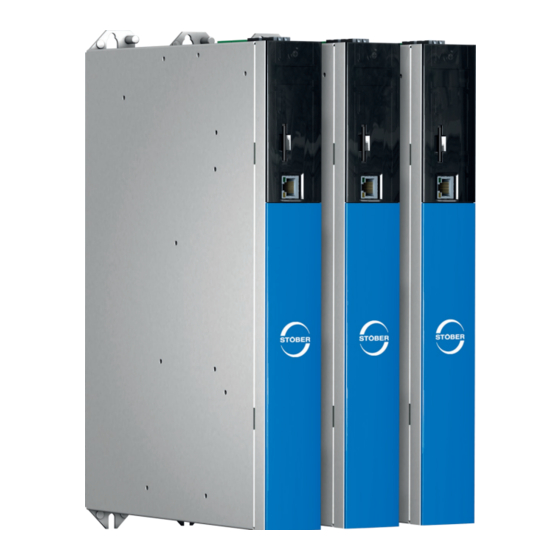
However, the SC6 can also be used in combination with asynchronous motors or synchronous servo motors with encoders (e.g. the STOBER EZ series). The SC6 is available in three sizes with a nominal output current of up to 19 A: sizes 0 and 1 as a double-axis controller, size 2 as a single-axis controller. -
Page 9: User Information
You will also find information on wiring the modules correctly and checking their functionality in the group with an initial test. Information To ensure proper functionality, we recommend using cables from STOBER that are matched to the complete system. If unsuitable connection cables are used, we reserve the right to reject claims under the warranty. Storage and transfer As this documentation contains important information for handling the product safely and efficiently, it must be stored in the immediate vicinity of the product until product disposal and be accessible to qualified personnel at all times. -
Page 10: Formatting Conventions
2 | User information STOBER Formatting conventions Orientation guides in the form of signal words, symbols and special text markups are used to emphasize specific information so that you are able identify it in this documentation quickly. 2.6.1 Use of symbols Safety instructions are identified with the following symbols. -
Page 11: Markup Of Text Elements
STOBER 2 | User information 2.6.2 Markup of text elements Certain elements of the continuous text are distinguished as follows. Important information Words or expressions with a special meaning Interpolated position mode Optional: File or product name or other name... -
Page 12: Conventions For Cables
2 | User information STOBER 2.6.3 Conventions for cables In the cable connection descriptions, core colors are shortened and used as follows. Cable colors BLACK PINK BROWN BLUE VIOLET GREEN WHITE GRAY YELLOW ORANGE Formatting conventions Two-colored core: WHYE WHITEYELLOW (white and yellow) -
Page 13: Trademarks
STOBER 2 | User information Trademarks The following names used in connection with the device, its optional equipment and its accessories are trademarks or registered trademarks of other companies: ® ® ® CANopen CANopen and CiA are registered European Union trademarks of CAN in ®... -
Page 14: General Safety Instructions
3 | General safety instructions STOBER General safety instructions There are risks associated with the product described in this documentation that can be prevented by complying with the described warning and safety instructions as well as the included technical rules and regulations. -
Page 15: Intended Use
As defined by DIN EN 50178, SC6 drive controllers are electrical devices operating as power electronics to control the flow of energy in high-voltage systems. They are intended solely for the operation of STOBER LM series Lean motors, synchronous servo motors (e.g. from the STOBER EZ series), asynchronous motors or torque motors. -
Page 16: Operational Environment And Operation
Use in potentially explosive atmospheres § Use in environments with harmful substances as specified by EN 60721, such as oils, acids, gases, vapors, dust and radiation Implementation of the following applications is permitted only after approval from STOBER: § Use in non-stationary applications §... -
Page 17: Working On The Machine
STOBER 3 | General safety instructions Working on the machine Before all work on machines and systems, apply the 5 safety rules in accordance with DIN VDE 0105-100 (Operation of electrical installations – Part 100: General requirements) in the order listed: §... -
Page 18: System Configuration
STOBER System configuration For connecting to a controller, we recommend the PROFINET fieldbus in combination with the STOBER Drive Based application. As an alternative, you can use the EtherCAT fieldbus and an application with a CiA 402 interface. You commission the drive controller using the DriveControlSuite software. -
Page 19: Hardware Components
STOBER 4 | System configuration Hardware components Below you will find an overview of the available hardware components. 4.1.1 Drive controllers The SC6 drive controller is available in three sizes. Various safety options are also available. The type specifications used in this documentation refer to the nameplate located on the side of the drive controller. -
Page 20: Fig. 3 Sticker With Mv And Serial Number
4 | System configuration STOBER Designation Value in example Meaning Type SC6A062 Production information ID No. 56690 027 HD Date 1602 9001303 Input voltage 3 × 400 V Input voltage 50 Hz UL: 3 × 480 V 50 – 60 Hz Input current 10.0 A... -
Page 21: Tab. 4 Example Code For Type Designation
STOBER 4 | System configuration 4.1.1.3 Type designation Tab. 4: Example code for type designation Code Designation Design Series ServoCompact Generation Generation 6 Version 0 – 2 Size Power output stage Power output stage within the size Axis controller Double-axis controller Single-axis controller... -
Page 22: Controller
4.1.3 Operating motors, encoders and brakes You can use the SC6 drive controller to operate STOBER Lean motors of the LM series, synchronous servo motors (such as those of the STOBER EZ series), asynchronous motors or torque motors. Evaluation options for feedback are available on the X4 connection for the following encoders: §... -
Page 23: Accessories
STOBER 4 | System configuration 4.1.4 Accessories You can find information about the available accessories in the following chapters. 4.1.4.1 Safety technology The safety modules are used to realize the STO safety function. They prevent the generation of a rotating magnetic field in the power unit of the drive controller. - Page 24 4 | System configuration STOBER 4.1.4.2 Communication The drive controller has two interfaces for the fieldbus connection on the top of the device as well as an Ethernet service port on the front of the device. Cables for the connection are available separately.
- Page 25 STOBER 4 | System configuration 4.1.4.3 DC link connection If you want to connect SC6 drive controllers into the DC link group, you will need Quick DC-Link modules of type DL6B. You receive the DL6B rear section modules in different designs for a horizontal connection, suitable for the size of the drive controller.
- Page 26 4 | System configuration STOBER 4.1.4.4 Braking resistor STOBER offers braking resistors in different sizes and performance classes. More detailed information can be found in the chapter Braking resistor [} 48]. 4.1.4.5 Encoder battery module Absolute Encoder Support AES ID No. 55452 Battery module for buffering the power supply when using the EnDat 2.2 digital...
-
Page 27: Software Components
Drive-based motion control is recommended for the decentralized motion control of sophisticated machines. The drive-based application package from STOBER is the right choice wherever universal and flexible solutions are needed. The STOBER Drive Based application provides drive-based motion control for positioning, velocity and torque/force with the PLCopen Motion Control command set. -
Page 28: Technical Data
5 | Technical data STOBER Technical data Technical data for the drive controllers and accessories can be found in the following chapters. Drive controllers The following chapters contain specifications for the electrical data, dimensions and weight of the drive controller. -
Page 29: Tab. 10 Discharge Times Of The Dc Link Circuit
STOBER 5 | Technical data Discharge times Self-discharge of DC link 15 min Tab. 10: Discharge times of the DC link circuit 5.1.2 Electrical data The electrical data of the available SC6 sizes as well as the properties of the brake chopper can be found in the following sections. -
Page 30: Tab. 12: Sc6 Electrical Data, Size 0
5 | Technical data STOBER 5.1.2.2 Power unit: Size 0 Electrical data SC6A062 3 × 400 V , +32% / −50%, 50/60 Hz; 3 × 480 V , +10% / −58%, 50/60 Hz 0 – 700 Hz 0 – max. U 270 µF 1400 µF maxPU Tab. -
Page 31: Tab. 16: Sc6 Electrical Data, Size 1
STOBER 5 | Technical data 5.1.2.3 Power unit: Size 1 Electrical data SC6A162 3 × 400 V , +32% / −50%, 50/60 Hz; 3 × 480 V , +10% / −58%, 50/60 Hz 0 – 700 Hz 0 – max. U 940 µF 1400 µF maxPU Tab. -
Page 32: Tab. 20: Sc6 Electrical Data, Size 2
5 | Technical data STOBER 5.1.2.4 Power unit: Size 2 Electrical data SC6A261 3 × 400 V , +32% / −50%, 50/60 Hz; 3 × 480 V , +10% / −58%, 50/60 Hz 0 – 700 Hz 0 – max. U 940 µF 1400 µF maxPU Tab. -
Page 33: Tab. 24 X101 Electrical Data
STOBER 5 | Technical data 5.1.2.5 Parallel connection The charging capacity of the driver controllers can be increased by a parallel connection only if the power grid supply is connected to all drive controllers simultaneously. Note the general conditions for parallel connection in the chapter Project configuration [} 52]. -
Page 34: Fig. 4 Asymmetric Load On Double-Axis Controllers
5 | Technical data STOBER 5.1.2.7 Single-ended nominal power consumption on double-axis controllers Operating two motors on one double-axis controller makes it possible to operate one of the motors with a continuous current above the nominal drive controller current if the continuous current of the second connected motor is lower than the nominal drive controller current. -
Page 35: Tab. 26 Power Loss Data Of The Sc6 Drive Controller In Accordance With En 61800-9-2
STOBER 5 | Technical data 5.1.2.8 Power loss data in accordance with EN 61800-9-2 Type Nominal Apparent Absolute Operating points IE class Compariso current power losses 2N,PU V,CU (0/25) (0/50) (0/100) (50/25) (50/50) (50/100) (90/50) (90/100) Relative losses [kVA] SC6A062 Max. -
Page 36: Derating
5 | Technical data STOBER 5.1.2.9 Power loss data of accessories If you intend to order the drive controller with accessory parts, losses increase as follows. Type Absolute losses Safety module SR6 Safety module SY6 Tab. 27: Absolute losses in the accessories Information Note the absolute power loss of the encoder (usually <... - Page 37 STOBER 5 | Technical data 5.1.3.2 Effect of the surrounding temperature Derating as a function of the surrounding temperature is determined as follows: § 0 °C to 45 °C: No restrictions (D = 100%) § 45 °C to 55 °C: Derating −2.5%/K Example The drive controller needs to be operated at 50 °C.
-
Page 38: Dimensions
5 | Technical data STOBER 5.1.4 Dimensions Fig. 5: SC6 dimensional drawing Dimension Size 0 Size 1 Size 2 Drive Controllers Width Depth Body height Fastening clip height Height incl. fastening clips Total height incl. shield connection Fastening holes (M5) Vertical distance... -
Page 39: Assignment Of Dl6B To Sc6
STOBER 5 | Technical data DC link connection The following section contains specifications for the electrical data, dimensions and weight of the DL6B modules Quick DC- Link. 5.2.1 General technical data The following information applies to all Quick DC-Link modules and corresponds to the general technical data for the base device. -
Page 40: Dimensions
5 | Technical data STOBER 5.2.3 Dimensions Fig. 6: DL6B dimensional drawing Dimension DL6B10 DL6B11 Quick DC-Link Width Depth Depth incl. attachment bolts Height Fastening clip height Height incl. fastening clips Fastening holes Vertical distance 393+2 (wall mounting) Vertical distance (module mounting) -
Page 41: Weight
STOBER 5 | Technical data 5.2.4 Weight Type Weight without packaging [g] Weight with packaging [g] DL6B10 DL6B11 Tab. 35: DL6B weight [g] Safety technology The SR6 option adds the STO safety function to the SC6 drive controller via terminal X12. -
Page 42: Operating Motors
5 | Technical data STOBER Operating motors The drive controller supports rotational motors with a number of motor poles from 2 to 120 poles (1 through 60 pole pairs). You can operate the following motors with the specified control modes. -
Page 43: Evaluable Encoders
STOBER 5 | Technical data Evaluable encoders The technical data of the evaluable encoder can be found in the following chapters. 5.5.1 Overview The following table explains which connections are available for the various encoders. Encoders Connection Note EnDat 2.2 digital —... -
Page 44: Tab. 39 Endat 2.1 Digital Specification
Max. cable length 100 m, shielded Tab. 39: EnDat 2.1 digital specification Information An EnDat 2.1 digital encoder can be connected only if certain general conditions are adhered to and STOBER has been consulted in advance. EnDat 2.2 digital encoders Specification EnDat 2.2 digital... -
Page 45: Tab. 42 Specification For Ttl Differential Incremental Signals
STOBER 5 | Technical data Incremental encoders Specification Incremental signals 12 V (unregulated) 250 mA 2max 1 MHz Signal level TTL, differential Max. cable length 100 m, shielded Tab. 42: Specification for TTL differential incremental signals Information Calculation example – Maximum frequency f for an encoder with 2,048 pulses per revolution: 3,000 revolutions per minute (equivalent to 50 revolutions per second) * 2,048 pulses per revolution = 102,400 pulses per second = 102.4 kHz <<... -
Page 46: X101 For Encoders
5 | Technical data STOBER Unsuitable encoder models The following STOBER encoder models may be connected: Encoder model Code according to type designation ECI 1118 EQI 1130 ECI 1319 EQI 1329 EQI 1331 Tab. 45: Encoder models with unsuitable supply voltage range 5.5.4... -
Page 47: Controllable Brakes
STOBER 5 | Technical data Controllable brakes The brake of axis A is connected to X2A. Connect the brake of axis B to X2B for double-axis controllers. You can control the following brakes: § Directly connected 24 V brakes § Indirectly connected brakes (e.g. over coupling contactor) The brake is supplied over X300. -
Page 48: Braking Resistor
STOBER Braking resistor In addition to drive controllers, STOBER offers the following braking resistors described below in various sizes and performance classes. For the selection, note the minimum permitted braking resistors specified in the technical data of the individual drive controller types. -
Page 49: Fig. 7 Fzmu (1), Fzzmu (2) Dimensional Drawing
STOBER 5 | Technical data Dimensions Dimension FZMU 400×65 FZZMU 400×65 ID No. 49010 53895 L x D 400 × 65 400 × 65 6.5 × 12 6.5 × 12 Tab. 51: FZMU, FZZMU dimensions [mm] Fig. 7: FZMU (1), FZZMU (2) dimensional drawing... -
Page 50: Flat Resistor Gvadu, Gbadu
5 | Technical data STOBER 5.8.2 Flat resistor GVADU, GBADU Type GVADU 210×20 GBADU 265×30 GBADU 335×30 ID No. 55441 55442 55443 SC6A062 — SC6A162 SC6A261 Tab. 52: Assignment of GVADU, GBADU braking resistor – SC6 drive controller Recommended Possible —... -
Page 51: Fig. 9 Gvadu, Gbadu Dimensional Drawing
STOBER 5 | Technical data Dimensions Dimension GVADU 210×20 GBADU 265×30 GBADU 335×30 ID No. 55441 55442 55443 18.2 28.8 28.8 10.8 10.8 β 65° 73° 73° Tab. 54: GVADU, GBADU dimensions [mm] Fig. 9: GVADU, GBADU dimensional drawing Fig. 10: GVADU, GBADU drilling diagram... -
Page 52: Project Configuration
6 | Project configuration STOBER Project configuration Relevant information on the project configuration and design of your drive system can be found in the following chapters. Drive controllers Minimum time between energizing two devices The drive controllers have temperature-dependent resistors in the charging circuit that prevent the devices from being damaged when being connected to the grid after a fault, such as a short-circuited DC link, incorrect wiring, etc. -
Page 53: Information On Design And Operation
STOBER 6 | Project configuration 6.2.1 Information on design and operation In order to connect the capacitors of multiple drive controllers, you need a separate Quick DC-Link module of type DL6B for each drive controller in the group. Information Note that Quick DC-Link can be subject to system or country-specific standards. -
Page 54: Design
6 | Project configuration STOBER 6.2.2 Design Charging capacity The charging circuit integrated into a drive controller can charge the DC links of other drive controllers in addition to its own DC link. Information When designing the Quick DC-Link, note that the sum of the charging capacities of the drive controllers connected to the grid is greater than or equal to the sum of the self-capacitances of all drive controllers in the DC link group. - Page 55 STOBER 6 | Project configuration Calculating motor rating and voltage The following formulas and assumptions are used to calculate the motor rating and voltage: ´ ´ ´ ´ ´ ´ l Line Line Line,nec Line 0,8 U ´ maxMOT LINE ´...
-
Page 56: Motors
6 | Project configuration STOBER Motors During the project configuration for motors, note the framework conditions described below. Rotational motors (Lean motors, synchronous servo motors, asynchronous motors, torque motors) The maximum possible motor speed is limited to 20000 rpm. The following relationship applies: Rotating magnetic field frequency = Motor speed ×... -
Page 57: Mixed Operation
Mixed operation You can combine the SC6 drive controller with other drive controllers from the 6th generation of STOBER drive controllers. In mixed operation, only device types of the same series may be supplied with power. The framework conditions for the supplying device apply. -
Page 58: Fig. 12 Grounding Concept In Mixed Operation With Si6 With Powered Sc6 Drive Controller
6 | Project configuration STOBER If you would like to connect two drive controllers directly via terminal X22 without a rear section module, there are special requirements for the connecting wiring: § The connection lines must satisfy a nominal voltage of up to 750 V to ground, e.g. -
Page 59: Storage
Reform drive controllers in storage annually or before commissioning. 7.1.1 Annual reforming To prevent damage to stored drive controllers, STOBER recommends connecting stored devices to the supply voltage once per year for one hour. The following graphics show the basic line connection for 3-phase devices. -
Page 60: Reforming Before Commissioning
7 | Storage STOBER 7.1.2 Reforming before commissioning If reforming is not possible every year, institute reforming on stored devices before commissioning. Note that the voltage levels depend on the storage time. The following graphic shows the predominant supply connection. -
Page 61: Installation
STOBER 8 | Installation Installation The following chapters describe the installation of a drive controller and the available accessories. Safety instructions for installation Installation work is permitted only when no voltage is present. Observe the 5 safety rules; see the chapter... -
Page 62: Braking Resistor
8 | Installation STOBER 8.2.2 Braking resistor Note the permitted mounting positions for the braking resistor. FZMU, FZZMU tubular fixed resistor Permitted installation: § On vertical surfaces with terminals downwards § On horizontal surfaces § In control cabinets Impermissible installation: §... -
Page 63: Minimum Clearances
STOBER 8 | Installation Minimum clearances Note the minimum clearances for installation below. Drive controller Fig. 15: Minimum clearances The specified dimensions relate to the outer edges of the drive controller. Minimum clearance A (above) B (below) C (on the side) -
Page 64: Drilling Diagrams And Bore Dimensions
8 | Installation STOBER Drilling diagrams and bore dimensions Drilling diagrams and bore dimensions can be found in the following chapters. 8.4.1 Drive controllers 1 – 2 Fig. 16: SC6 and DL6B drilling diagram The bore dimensions depend on the selected design. -
Page 65: Length Of Copper Rails
STOBER 8 | Installation The following specifications apply to installation with Quick DC-Link DL6B: DL6B dimensions Size 0 Size 1, size 2 Horizontal fastening holes Size 0 46±1 56±1 ∅ 4.2 (M5) Size 1, size 2 56±1 66±1 Vertical fastening 393+2 393+2 holes ∅ 4.2 (M5) Tab. -
Page 66: Installing The Drive Controller Without A Rear Section Module
8 | Installation STOBER Installing the drive controller without a rear section module This chapter describes the installation of the SC6 drive controller without a rear section module. If you would like to connect the drive controllers in the DC link, you must mount the required rear section modules and then build the appropriate drive controllers over them. -
Page 67: Installing The Dc Link Connection
STOBER 8 | Installation Installing the DC link connection DANGER! Electrical voltage! Risk of fatal injury due to electric shock! ▪ Always switch off all power supply voltage before working on the devices! ▪ Note the discharge time of the DC link capacitors in the general technical data. You can only determine the absence of voltage after this time period. - Page 68 8 | Installation STOBER 2. Insert the insulation connection pieces between the modules and insulation end section each at the left edge of the first module and at the right edge of the last module. Ensure correct alignment of the end section using the marking on the outside and the insertion aids for the copper rails on the inside.
-
Page 69: Mounting The Drive Controller On The Rear Section Module
STOBER 8 | Installation 6. Fasten each of the copper rails with two quick fastening clamps per rail and Quick DC-Link module. Make certain the contact points of the copper rails do not become contaminated. ð You have installed the Quick DC-Link. In the next step, build over the Quick DC-Link modules with the appropriate drive controllers. - Page 70 8 | Installation STOBER Requirements and installation Perform the following steps for each drive controller within the group. ü There is a circuit diagram of the system that describes the connection of the drive controllers. ü For each drive controller, the appropriate DL6B Quick DC-Link rear section modules for the DC link connection have already been installed in the installation position.
- Page 71 STOBER 8 | Installation 3. Fasten the drive controller to both threaded bolts of the Quick DC-Link module using the nut and washer assemblies (M5). The nut and washer assemblies are included with the Quick DC-Link module. 4. Connect the grounding conductor to the ground bolt. Note the instructions and requirements in the chapter...
-
Page 72: Connection
9 | Connection STOBER Connection The following chapter describes the connection of the drive controller and the available accessories. Safety instructions for connection Connection work is permitted only when no voltage is present. Observe the 5 safety rules; see the chapter... -
Page 73: Protective Measures
STOBER 9 | Connection Protective measures Take the following protective measures into account. 9.3.1 Power grid supply in case of parallel connection All drive controllers must be connected to the same supply grid. ATTENTION! Damage to device due to the emission of electromagnetic interference! If the EMC threshold limits are exceeded during the operation of a DC link connection, devices in the immediate area can be interrupted or damaged. -
Page 74: Line Fuse
9 | Connection STOBER 9.3.2 Line fuse The line fuse ensures the line and overload protection in the drive controller. Observe the requirements described below, which vary based on the configuration. 9.3.2.1 Line fuse in stand-alone operation Information To ensure problem-free operation, always comply with the recommended trigger limits and trigger characteristics of the fuse elements. -
Page 75: Tab. 59 Recommended Line Fuse In Parallel Connection
STOBER 9 | Connection 9.3.2.2 Line fuse in case of parallel connection Every drive controller connected to the grid in the DC link group must be protected at the line input against overload and short circuit. To do this, a fuse combination consisting of overload protection and solid state short circuit protection is connected in series. -
Page 76: Grid Connection In Case Of Parallel Connection
9.3.4 Residual current protective device STOBER devices can be protected with a residual current protective device (RCD) to detect residual currents. Residual current protective devices prevent electrical accidents, especially ground fault through the body. They are generally classified by their triggering limit and suitability for detecting different types of residual currents. -
Page 77: Housing Grounding
STOBER 9 | Connection Information Check whether the use of residual current protective devices with increased trigger current as well as with short-time delayed or delayed switch-off trigger characteristics are permitted in your application. DANGER! Electrical voltage! Risk of fatal injury due to electric shock! Leakage and residual currents with a DC current component can restrict the functionality of type A and AC residual current protective devices. -
Page 78: Emc Recommendations
9 | Connection STOBER Leakage currents > 10 mA can arise in normal operation. To fulfill DIN EN 61800-5-1 and EN 60204-1, connect the grounding bolt with a copper conductor according to the following table: Cross-section A Minimum cross-section A Power grid line Grounding conductor at grounding bolt A ≤... -
Page 79: Drive Controller
STOBER 9 | Connection Drive controller The following section contains detailed information about the terminals and the correct connection of the drive controller. 9.4.1 Overview X20B X700 X300 X20A X103 X101 X201 X200 Fig. 19: Connection overview using the example of the SC6A162... -
Page 80: X2A: Brake A
The brake of axis A is connected to X2A. All device types of the SC6 drive controller can control a 24 V brake as standard. Information Note that brakes from other manufacturers may be connected only after consultation with STOBER. Controllable brakes Note the technical data of the brakes controllable at X2A; see the chapter Controllable brakes [} 47]. -
Page 81: X2A: Motor Temperature Sensor A
STOBER 9 | Connection 9.4.3 X2A: Motor temperature sensor A The motor temperature sensor of axis A is connected to terminal X2A. All device types of the SC6 drive controller have connections for thermistors. You can connect a maximum of two PTC triplets to X2A. -
Page 82: X4A: Encoder A
9 | Connection STOBER 9.4.6 X4A: Encoder A The encoder of axis A is connected to terminal X4A. ATTENTION! Risk of encoder destruction! X4 may not be plugged in or unplugged when the device is switched on! ATTENTION! Risk of encoder destruction! Only encoders with a suitable input voltage range (minimum 12 V... -
Page 83: Tab. 66 X4A Connection Description For Differential Ttl And Differential Htl Incremental Encoders (Htl Via Ht6 Adapter)
STOBER 9 | Connection Differential TTL and differential HTL incremental encoders (HTL via HT6 adapter) Socket Designation Function 8|7|6|5|4|3|2|1 — — Reference potential for encoder supply to pin 4 — — 15|14|13|12|11|10|9 Encoder supply Differential input for B channel —... -
Page 84: Tab. 68 X4A Connection Description For Hiperface Dsl Encoders
Tab. 69: Cable length [m] Information To ensure proper functionality, we recommend using cables from STOBER that are matched to the complete system. If unsuitable connection cables are used, we reserve the right to reject claims under the warranty. Unsuitable encoder models... -
Page 85: X4B: Encoder B
STOBER 9 | Connection 9.4.6.1 AP6 interface adapter (resolver) AP6A00 – resolver (9-pin to 15-pin) Socket Designation Function Connector 1 | 2 | 3 | 4 | 5 — — — 1|2|3|4|5|6|7|8|9 1TP1 — — S2 Sin− Sin input reference potential S1 Cos−... -
Page 86: X10: 400 V Supply
STOBER Information To ensure proper functionality, we recommend using cables from STOBER that are matched to the complete system. If unsuitable connection cables are used, we reserve the right to reject claims under the warranty. It is also possible to use cables with the following specification:... -
Page 87: X11: 24 V Supply
STOBER 9 | Connection 9.4.10 X11: 24 V supply The connection of 24 V to X11 is required for the power supply of the control unit. ATTENTION! Device damage due to overload! If the 24 V power supply is looped to multiple devices over the terminal, the terminal may be damaged by a current that is too high. -
Page 88: X12: Safety Technology (Option Sr6)
9 | Connection STOBER 9.4.11 X12: Safety technology (option SR6) The SR6 option adds the STO safety function to the SC6 drive controller via terminal X12. For double-axis controllers, the STO safety function has a two-channel structure that acts upon both axes. -
Page 89: X20A: Motor A
Tab. 84: Maximum cable length of the power cable [m] Information To ensure proper functionality, we recommend using cables from STOBER that are matched to the complete system. If unsuitable connection cables are used, we reserve the right to reject claims under the warranty. -
Page 90: X20B: Motor B
9 | Connection STOBER 9.4.13 X20B: Motor B The motor of axis B is connected to X20B for double-axis controllers. Only X20A is available for single-axis controllers. The connection description of X20B matches the X20A description. 9.4.14 X21: Braking resistor Terminal X21 is available for the connection of a braking resistor. -
Page 91: X22: Dc Link Connection
STOBER 9 | Connection 9.4.15 X22: DC link connection Terminal X22 is available for the DC link connection of the drive controller. For setting up the Quick DC-Link, note the information on project configuration in the chapter DC link connection [} 52]. -
Page 92: X101: Be1 - Be4
9 | Connection STOBER 9.4.16 X101: BE1 – BE4 The binary inputs 1 to 4 are available on terminal X101. X101 for binary signals For evaluating binary signals at X101, note the specification for the binary inputs in the technical data of the drive... -
Page 93: X103: Be6 - Be9
STOBER 9 | Connection 9.4.17 X103: BE6 – BE9 The binary inputs 6 to 9 are available on terminal X103. X103 for binary signals For the evaluation of binary signals at X103, observe the technical data of the drive controller; see the chapter Binary inputs [} 33]. -
Page 94: X200, X201: Ethercat
Cable requirements Information To ensure proper functionality, we recommend using cables from STOBER that are matched to the complete system. If unsuitable connection cables are used, we reserve the right to reject claims under the warranty. STOBER provides ready-made cables for the EtherCAT connection. It is also possible to use cables with the following specification: Ethernet patch cables or crossover cables meeting the CAT 5e quality level are the ideal cables. -
Page 95: X200, X201: Profinet
STOBER 9 | Connection 9.4.19 X200, X201: PROFINET In order to be able to connect the drive controllers to other PROFINET nodes, an integrated switch with both X200 and X201 RJ-45 sockets is provided. The sockets are located on top of the device. The associated pin assignment and color coding correspond to the EIA/TIA-T568B standard. -
Page 96: X300: Brake 24 V Supply
SDHC cards with a storage capacity of 64 GB can be used only if they have been first reformatted to max. 32 GB. Since higher capacities increase the controller starting time, STOBER recommends the use of cards with a storage capacity from 2 to 4 GB. -
Page 97: Connecting A Drive Controller
STOBER 9 | Connection 9.4.22 Connecting a drive controller DANGER! Electrical voltage! Risk of fatal injury due to electric shock! ▪ Always switch off all power supply voltage before working on the devices! ▪ Note the discharge time of the DC link capacitors in the general technical data. You can only determine the absence of voltage after this time period. - Page 98 9 | Connection STOBER Top of the device: ü You have a system circuit diagram describing the connection of the drive controller. 1. Connect the power supply to terminal X10 and attach the terminal. 2. Connect the 24 V power supply for the control electronics to terminal X11 and attach the terminal.
-
Page 99: Braking Resistor
STOBER 9 | Connection Braking resistor Housing grounding of the braking resistor Note the information on connecting the grounding conductor in the chapter Housing grounding [} 77] for the braking resistor housing ground. 9.5.1 FZMU, FZZMU connection description The internal connections of the tubular fixed resistor are wired to terminals with heat-resistant, silicone-insulated strands of wire. -
Page 100: Gvadu, Gbadu Connection Description
When using a motor brake, pay attention to the voltage drop in the supply voltage on the line. Information To ensure proper functionality, we recommend using cables from STOBER that are matched to the complete system. If unsuitable connection cables are used, we reserve the right to reject claims under the warranty. -
Page 101: Power Cables
STOBER 9 | Connection 9.6.1 Power cables Synchronous servo motors and Lean motors from STOBER are equipped with plug connectors as standard. STOBER provides suitable cables in various lengths, conductor cross-sections and connector sizes. 9.6.1.1 Connection description Depending on the size of the motor plug connector, power cables are available in the following designs: §... -
Page 102: Tab. 106 Con.15 Power Cable Pin Assignment
9 | Connection STOBER Power cables – con.15 plug connector Motor Cable Drive controller (3) – (5) Motor connection Designation Int. motor Core No./ diagram Core color Core color X300 — — — — — — 1TP1 — — 1TP2 —... -
Page 103: Tab. 110 Con.40 Power Cable Pin Assignment
STOBER 9 | Connection Power cables – con.40 plug connectors Motor Cable Drive controller (3) – (5) Motor Designation Int. motor Core No./ connection Core color Core color X300 diagram — — — — — — 1BD1 — — −... -
Page 104: Encoder Cables
STOBER 9.6.2 Encoder cables STOBER motors are equipped with encoder systems and plug connectors as standard. STOBER provides suitable cables in various lengths, conductor cross-sections and connector sizes. Depending on the respective motor types, different encoder systems can be used. -
Page 105: Tab. 112 Con.15 Encoder Cable Pin Assignment, Endat 2.1/2.2 Digital
STOBER 9 | Connection Encoder cables – con.15 plug connector The power supply is buffered for EnDat 2.2 digital "EBI 1135" and "EBI 135" inductive encoders with a multi-turn function. In this case, pin 2 and pin 3 of the motor are assigned to the U buffer battery. -
Page 106: Tab. 114 Con.17 Encoder Cable Pin Assignment, Endat 2.1/2.2 Digital
9 | Connection STOBER Encoder cables – con.17 plug connector The power supply is buffered for EnDat 2.2 digital "EBI 1135" and "EBI 135" inductive encoders with a multi-turn function. In this case, pin 2 and pin 3 of the motor are assigned to the U buffer battery. -
Page 107: Tab. 116 Con.23 Encoder Cable Pin Assignment, Endat 2.1/2.2 Digital
STOBER 9 | Connection Encoder cables – con.23 plug connector Motor Cable Drive controller Connection diagram Designation Core color Core color Clock+ Sense U — — — — — — — — Data− Data+ — — — — Clock− —... -
Page 108: Tab. 117 Con.23 Dimensions
Suitable encoder cables are described below. 9.6.2.2.1 Connection description The encoder cable is available in plug connector size con.23 with a speedtec quick lock. con.23 Plug connectors STOBER encoder cable D-sub X4 Encoder cables – con.23 plug connector Motor Cable Drive controller... -
Page 109: Tab. 120 Con.23 Encoder Cable Pin Assignment, Incremental Htl
The encoder cable is available in plug connector size con.23 with a speedtec quick lock. con.23 Plug connectors STOBER encoder cable D-sub X4 Information For the connection of an HTL incremental encoder to terminal X4 of the SC6 or SI6 drive controller, you need the HT6 adapter (ID No. - Page 110 Depending on the size of the motor plug connector, encoder cables are available in the following designs: § springtec quick lock for con.15 § speedtec quick lock for con.17 and con.23 con.15 con.17 con.23 Plug connector STOBER encoder cable D-sub X4...
-
Page 111: Tab. 122 Con.15 Encoder Cable Pin Assignment, Resolver
STOBER 9 | Connection Encoder cables – con.15 plug connector Motor Cable Drive controller Connection diagram Designation Core color Core color S3 Cos+ S1 Cos− S4 Sin+ S2 Sin− 1TP1 1TP2 R2 Ref+ YEWH/ BKWH R1 Ref− RDWH — —... -
Page 112: Tab. 124 Con.17 Encoder Cable Pin Assignment, Resolver
9 | Connection STOBER Encoder cables – con.17 plug connector Motor Cable Drive controller Connection diagram Designation Core color Core color S3 Cos+ S1 Cos− S4 Sin+ S2 Sin− 1TP1 1TP2 R2 Ref+ YEWH/ BKWH R1 Ref− RDWH — —... -
Page 113: Tab. 126 Con.23 Encoder Cable Pin Assignment
STOBER 9 | Connection Encoder cables – con.23 plug connector Information For connecting STOBER resolver cables with a 9-pin D-sub connector, you also require the AP6A00 interface adapter (ID No. 56498, 9-pin to 15-pin D-sub), available separately. Motor Cable Drive controller... -
Page 114: One Cable Solution
Information For connecting as a One Cable Solution, use exclusively hybrid cables from STOBER. The use of unsuitable cables or poorly made connections can cause subsequent damage. For this reason, we reserve the right to reject claims under the warranty in this case. -
Page 115: Tab. 128 Con.23 Hybrid Cable Pin Assignment
STOBER 9 | Connection Hybrid cables – con.23 plug connectors Motor Cable Drive controller (3) – (5) Connection diagram Designation Core color Core No./ Core color — — — — — — DSL− — — DSL shield — — —... -
Page 116: Commissioning
[} 196]. For the components of your drive model, we require one of the following two combinations: STOBER synchronous servo motor with EnDat 2.2 digital encoder or HIPERFACE DSL encoder (and optional brake) These motors together with all relevant data for the project configuration are saved in the motor database of... -
Page 117: Initiating The Project
Description: If necessary specify supporting additional information such as the change history of the project configuration. Drive controller tab: Select the SC6 series and the device type of the drive controller. Option modules tab: Safety module: If the drive controller is part of a safety circuit, select the SR6 or SY6 safety module. -
Page 118: Configuring Safety Technology
10 | Commissioning STOBER Projecting the axis 1. Click on Axis Properties tab: Establish the connection between your circuit diagram and the axis to be projected in DriveControlSuite. Reference: Specify the reference code (equipment code) of the axis. Designation: Give the axis a unique name. -
Page 119: Specifying A Module
STOBER 10 | Commissioning 10.1.4 Specifying a module After you have created and projected all the drive controllers that you would like to gather under one module, specify the module. 1. Highlight the module M1: Module 1 in the project tree. -
Page 120: Parameterizing The Stober Motor
Parameterizing the STOBER motor You have projected one of the following motors: STOBER synchronous servo motor with EnDat 2.2 digital encoder or HIPERFACE DSL encoder (with optional brake) By projecting the corresponding motor, limit values for currents and torques as well as associated temperature data are automatically transferred to the respective parameters of the individual wizards. - Page 121 STOBER 10 | Commissioning 10.2.2.1 Define the axis model 1. Highlight the relevant drive controller in the project tree and click on the first projected axis in the project menu > Wizard area. 2. Select the Axis model wizard. 3. I05 Type of axis: In order to configure the units of measure and the number of decimal places individually for specifying and displaying position set values, velocities and accelerations, select 0: User defined, rotational or 1: User defined, translational.
- Page 122 10 | Commissioning STOBER 10.2.2.3 Parameterizing the position and velocity range Enter position limits and velocity zones for set values, i.e. parameterize boundary values for reaching a position or velocity. 1. Select the Axis model wizard > Window position, velocity.
-
Page 123: Testing The Project Configuration
STOBER 10 | Commissioning Limiting torque/force (optional) The specified default values take into account the rated operation together with the overload reserves. 1. Select the Axis model wizard > Limit: Torque/force. 2. If the motor force must be limited, adapt the saved values as necessary. - Page 124 10 | Commissioning STOBER Saving the test configuration 1. In the project tree, highlight the drive controller to which you have transferred the test configuration and click on the first projected axis in the project menu > Wizard area. 2. Select the Save values wizard >...
-
Page 125: Communication
Also observe the notes in the chapter Communication requirements [} 200]. Virtual machines If you would like to connect STOBER drive controllers to DriveControlSuite from a virtual machine, observe the information in the chapter Configuring virtual machines [} 201]. 11.2 Fieldbus... -
Page 126: Diagnostics
DriveControlSuite commissioning software. 12.1 Drive controller STOBER drive controllers have diagnostic LEDs that visually indicate the state of the drive controller as well as the states of the physical connection and communication. FSoE Fig. 22: Positions of the diagnostic LEDs on the front and top of the drive controller... -
Page 127: Fieldbus State
STOBER 12 | Diagnostics 12.1.1 Fieldbus state The LEDs for the diagnostics of the fieldbus state vary depending on the implemented fieldbus system or communication module. 12.1.1.1 EtherCAT state There are 2 LEDs on the front of the drive controller that provide information about the connection between EtherCAT master and slave and about the state of the data exchange. -
Page 128: Fig. 24 Leds For The Profinet State
12 | Diagnostics STOBER 12.1.1.2 PROFINET state There are 2 LEDs on the front of the drive controller that provide information about the connection between the IO controller and device and about the state of the data exchange. This information can also be read out in parameter A271 PN state. -
Page 129: Fsoe State
STOBER 12 | Diagnostics 12.1.2 FSoE state If the drive controller includes the SY6 safety module, the STO and SS1 safety functions are activated over EtherCAT FSoE. In this case, an LED on the front of the device provides information about the state of FSoE communication. This information can also be read out in parameter S20 FSoE status indicator. -
Page 130: Drive Controller State
12 | Diagnostics STOBER 12.1.3 Drive controller state 3 LEDs on the front of the device provide information about the state of the drive controller. Fig. 26: LEDs for the state of the drive controller Green: Run Red: Error in axis controller A... -
Page 131: Tab. 140 States Of The Leds When Using An Sd Card To Transfer A Firmware File
STOBER 12 | Diagnostics Pattern when transferring a firmware file using DriveControlSuite The states of the green and red LEDs also apply as described when transferring a firmware file using DriveControlSuite. Pattern when transferring a firmware file using an SD card... -
Page 132: Service Network Connection
12 | Diagnostics STOBER 12.1.4 Service network connection The LEDs at X9 on the front of the device display the state of the service network connection. Fig. 27: LEDs for the state of the service network connection Green: Link Yellow: Activity... -
Page 133: Fieldbus Network Connection
STOBER 12 | Diagnostics 12.1.5 Fieldbus network connection The LEDs for communication diagnostics vary depending on implemented fieldbus system or communication module. 12.1.5.1 EtherCAT network connection The LEDs LA IN and LA OUT at X200 and X201 on the top of the device indicate the state of the EtherCAT network connection. -
Page 134: Fig. 29 Leds For The State Of The Profinet Network Connection
12 | Diagnostics STOBER 12.1.5.2 PROFINET network connection The Act. and Link LEDs at X200 and X201 on the top of the device indicate the state of the PROFINET network connection. Fig. 29: LEDs for the state of the PROFINET network connection... -
Page 135: Events
STOBER 12 | Diagnostics 12.2 Events The drive controller has a self-monitoring system that uses test rules to protect the drive system from damage. Violating the test rules triggers a corresponding event. There is no possible way for you as the user to intervene in some events, such as the Short/ground event. - Page 136 12 | Diagnostics STOBER Event Event 60: Application event 0 – Event 67: Application event 7 [} 160] Event 68: External fault 2 [} 161] Event 69: Motor connection [} 162] Event 70: Parameter consistency [} 163] Event 71: Firmware [} 164] Event 72: Brake test timeout [} 165] Event 76: Position encoder [} 166]...
-
Page 137: Event 31: Short/Ground
STOBER 12 | Diagnostics 12.2.2 Event 31: Short/ground The drive controller is interrupted: § The power unit is disabled and axis movement is no longer controlled by the drive controller § The brakes are no longer controlled by the drive controller and engage in the event of an inactive release override (F06) The brake chopper is disabled. -
Page 138: Event 33: Overcurrent
The drive controller is interrupted with emergency braking if: § U30 = 1: Active and § A29 = 1: Active for STOBER device controller § U30 = 1: Active and § A540 = 2: slow down on quick stop ramp for CiA 402 device controller Response: §... -
Page 139: Event 34: Hardware Fault
STOBER 12 | Diagnostics 12.2.5 Event 34: Hardware fault The drive controller is interrupted: § The power unit is disabled and axis movement is no longer controlled by the drive controller § The brakes are no longer controlled by the drive controller and engage in the event of an inactive release override... -
Page 140: Event 36: High Voltage
The drive controller is interrupted with emergency braking if: § U30 = 1: Active and § A29 = 1: Active for STOBER device controller § U30 = 1: Active and § A540 = 2: slow down on quick stop ramp for CiA 402 device controller Response: §... - Page 141 STOBER 12 | Diagnostics Number Cause Check and action 1: Parameter <-> encoder Inconsistent parameterization Compare the specification of the connected encoder to the corresponding values of the H parameters and correct them if necessary 2: X4 speed Exceeded encoder maximum...
- Page 142 (H00) Incompatible encoder Compare the specification of the encoder with the corresponding specifications from STOBER and replace the motor if necessary 17: EBI encoder low battery Battery in battery module weak Replace the battery; reference remains intact...
-
Page 143: Event 38: Temperature Drive Controller Sensor
12 | Diagnostics 12.2.9 Event 38: Temperature drive controller sensor The drive controller is interrupted if: § A29 = 0: Inactive for STOBER device controller § A540 = 0: disable drive, motor is free to rotate for CiA device controller Response: §... -
Page 144: Event 39: Overtemperature Drive Controller I2T
(E24) increases to 105%, event 59: 2N,PU Overtemperature drive controller i2t is triggered. The drive controller is interrupted if: § A29 = 0: Inactive for STOBER device controller § A540 = 0: disable drive, motor is free to rotate for CiA device controller Response: §... -
Page 145: Event 40: Invalid Data
STOBER 12 | Diagnostics 12.2.11 Event 40: Invalid data The drive controller is interrupted: § The power unit is disabled and axis movement is no longer controlled by the drive controller § The brakes are no longer controlled by the drive controller and engage in the event of an inactive release override... -
Page 146: Event 41: Temp.motortmp
2: Warning § 3: Fault The drive controller is interrupted if: § A29 = 0: Inactive for STOBER device controller § A540 = 0: disable drive, motor is free to rotate for CiA device controller Response: § The power unit is disabled and axis movement is no longer controlled by the drive controller §... -
Page 147: Event 42: Tempbrakeres
12 | Diagnostics 12.2.13 Event 42: TempBrakeRes The drive controller is interrupted if: § A29 = 0: Inactive for STOBER device controller § A540 = 0: disable drive, motor is free to rotate for CiA device controller Response: § The power unit is disabled and axis movement is no longer controlled by the drive controller §... -
Page 148: Event 44: External Fault 1
STOBER 12.2.14 Event 44: External fault 1 The drive controller is interrupted if: § A29 = 0: Inactive for STOBER device controller § A540 = 0: disable drive, motor is free to rotate for CiA device controller Response: § The power unit is disabled and axis movement is no longer controlled by the drive controller §... -
Page 149: Event 45: Overtemp.motor I2T
2: Warning § 3: Fault The drive controller is interrupted if: § A29 = 0: Inactive for STOBER device controller § A540 = 0: disable drive, motor is free to rotate for CiA device controller Response: § The power unit is disabled and axis movement is no longer controlled by the drive controller §... -
Page 150: Event 46: Low Voltage
2: Warning § 3: Fault The drive controller is interrupted if: § A29 = 0: Inactive for STOBER device controller § A540 = 0: disable drive, motor is free to rotate for CiA device controller Response: § The power unit is disabled and axis movement is no longer controlled by the drive controller §... -
Page 151: Event 47: Torque Limit
Check the general machine limit and adjust it if necessary (C03, C05); check the limits application limits and the parameters dependent on the operating mode and adjust them if necessary (STOBER C132, C133 or CiA 402 A559) Wrong motor design Check the design and change the motor type if necessary... -
Page 152: Event 50: Safety Module
12 | Diagnostics STOBER 12.2.18 Event 50: Safety module The drive controller is interrupted: § The power unit is disabled and axis movement is no longer controlled by the drive controller § The brakes are no longer controlled by the drive controller and engage in the event of an inactive release override... -
Page 153: Event 51: Virtual Master Limit Switch
1: Message § 3: Fault The drive controller is interrupted if: § A29 = 0: Inactive for STOBER device controller § A540 = 0: disable drive, motor is free to rotate for CiA device controller Response: § The power unit is disabled and axis movement is no longer controlled by the drive controller §... -
Page 154: Event 52: Communication
STOBER 12.2.20 Event 52: Communication The drive controller is interrupted if: § A29 = 0: Inactive for STOBER device controller § A540 = 0: disable drive, motor is free to rotate for CiA device controller Response: § The power unit is disabled and axis movement is no longer controlled by the drive controller §... -
Page 155: Event 53: Limit Switch
12 | Diagnostics 12.2.21 Event 53: Limit switch The drive controller is interrupted if: § A29 = 0: Inactive for STOBER device controller § A540 = 0: disable drive, motor is free to rotate for CiA device controller Response: §... -
Page 156: Event 54: Following Error
(STOBER C132, C133 and the parameters dependent on the operating mode or CiA 402 A559) Maximum permitted drag distance Check the maximum permitted drag error and correct it if necessary (STOBER I21 or too small CiA A546) -
Page 157: Event 56: Overspeed
The drive controller is interrupted with emergency braking if: § U30 = 1: Active and § A29 = 1: Active for STOBER device controller § U30 = 1: Active and § A540 = 2: slow down on quick stop ramp for CiA 402 device controller Response: §... -
Page 158: Event 57: Runtime Usage
STOBER 12.2.24 Event 57: Runtime usage The drive controller is interrupted if: § A29 = 0: Inactive for STOBER device controller § A540 = 0: disable drive, motor is free to rotate for CiA device controller Response: § The power unit is disabled and axis movement is no longer controlled by the drive controller §... -
Page 159: Event 59: Overtemperature Drive Controller I2T
12 | Diagnostics 12.2.25 Event 59: Overtemperature drive controller i2t The drive controller is interrupted if: § A29 = 0: Inactive for STOBER device controller § A540 = 0: disable drive, motor is free to rotate for CiA device controller Response: §... -
Page 160: Event 60: Application Event 0 - Event 67: Application Event 7
2: Warning § 3: Fault The drive controller is interrupted if: § A29 = 0: Inactive for STOBER device controller § A540 = 0: disable drive, motor is free to rotate for CiA device controller Response: § The power unit is disabled and axis movement is no longer controlled by the drive controller §... -
Page 161: Event 68: External Fault 2
12 | Diagnostics 12.2.27 Event 68: External fault 2 The drive controller is interrupted if: § A29 = 0: Inactive for STOBER device controller § A540 = 0: disable drive, motor is free to rotate for CiA device controller Response: §... -
Page 162: Event 69: Motor Connection
0: Inactive § 3: Fault The drive controller is interrupted if: § A29 = 0: Inactive for STOBER device controller § A540 = 0: disable drive, motor is free to rotate for CiA device controller Response: § The power unit is disabled and axis movement is no longer controlled by the drive controller §... -
Page 163: Event 70: Parameter Consistency
STOBER 12 | Diagnostics 12.2.29 Event 70: Parameter consistency The drive controller is interrupted: § The power unit is disabled and axis movement is no longer controlled by the drive controller § The brakes are no longer controlled by the drive controller and engage in the event of an inactive release override... -
Page 164: Event 71: Firmware
The brakes are no longer controlled by the drive controller and engage in the event of an inactive release override (F06) Cause 3: The drive controller is interrupted if: § A29 = 0: Inactive for STOBER device controller § A540 = 0: disable drive, motor is free to rotate for CiA device controller Response: §... -
Page 165: Event 72: Brake Test Timeout
STOBER 12 | Diagnostics 12.2.31 Event 72: Brake test timeout The possible effects depend on the cause. Cause 1 and 2 lead to a fault, cause 3 is output as a message. The drive controller is interrupted: § The power unit is disabled and axis movement is no longer controlled by the drive controller §... -
Page 166: Event 76: Position Encoder
The drive controller is interrupted if: § U30 = 0: Inactive and § A29 = 0: Inactive for STOBER device controller § U30 = 1: Active and § A540 = 0: disable drive, motor is free to rotate for CiA 402 device controller Response: §... - Page 167 Check the cable and replace it if necessary Inconsistent parameterization Compare the connected encoder to the parameterized encoder and correct it if necessary (H00) Incompatible encoder Compare the specification of the encoder with the corresponding specifications from STOBER and replace the encoder or motor if necessary...
- Page 168 Check the cable and replace it if necessary – Incompatible encoder Compare the specification of the encoder with 22: Resolver overvoltage the corresponding specifications from STOBER and replace the encoder or motor if necessary; fault cannot be acknowledged 24: Resolver failure Defective encoder cable...
-
Page 169: Event 77: Master Encoder
12 | Diagnostics 12.2.33 Event 77: Master encoder The drive controller is interrupted if: § A29 = 0: Inactive for STOBER device controller § A540 = 0: disable drive, motor is free to rotate for CiA device controller Response: §... - Page 170 (H00) Incompatible encoder Compare the specification of the encoder with the corresponding specifications from STOBER and replace the encoder if necessary 17: EBI encoder low battery Battery in battery module Replace the battery; reference is not deleted by the...
-
Page 171: Event 78: Position Limit Cyclic
Check the set position in the controller and software limit switch software limit switch in the drive controller and correct it if necessary (STOBER I50, I51 or CiA 402 A570) 2: Reference value outside of Set position outside of the travel... -
Page 172: Event 79: Motor / Position Monitor
1: Message § 3: Fault The drive controller is interrupted if: § A29 = 0: Inactive for STOBER device controller § A540 = 0: disable drive, motor is free to rotate for CiA device controller Response: § The power unit is disabled and axis movement is no longer controlled by the drive controller §... -
Page 173: Event 80: Illegal Action
STOBER 12 | Diagnostics 12.2.36 Event 80: Illegal action The drive controller is interrupted: § The power unit is disabled and axis movement is no longer controlled by the drive controller § The brakes are no longer controlled by the drive controller and engage in the event of an inactive release override... -
Page 174: Event 83: Failure Of One/ All Phases (Mains)
Upon the occurrence of an event, a warning is output initially, becoming a fault after a 10 s warning period. The drive controller is interrupted if: § A29 = 0: Inactive for STOBER device controller § A540 = 0: disable drive, motor is free to rotate for CiA device controller Response: §... -
Page 175: Event 84: Drop In Network Voltage When Power Section Active
The drive controller is interrupted if: § U30 = 0: Inactive and § A29 = 0: Inactive for STOBER device controller § U30 = 1: Active and § A540 = 0: disable drive, motor is free to rotate for CiA 402 device controller Response: §... -
Page 176: Event 85: Excessive Jump In Reference Value
12.2.40 Event 85: Excessive jump in reference value The drive controller is interrupted if: § A29 = 0: Inactive for STOBER device controller § A540 = 0: disable drive, motor is free to rotate for CiA device controller Response: §... -
Page 177: Event 86: Unknown Leanmotor Record
12 | Diagnostics 12.2.41 Event 86: Unknown LeanMotor record The drive controller is interrupted if: § A29 = 0: Inactive for STOBER device controller § A540 = 0: disable drive, motor is free to rotate for CiA device controller Response: §... -
Page 178: Event 87: Reference Lostreference Loss
STOBER 12.2.42 Event 87: Reference lostReference loss The drive controller is interrupted if: § A29 = 0: Inactive for STOBER device controller § A540 = 0: disable drive, motor is free to rotate for CiA device controller Response: § The power unit is disabled and axis movement is no longer controlled by the drive controller §... -
Page 179: Event 88: Control Panel
12 | Diagnostics 12.2.43 Event 88: Control panel The drive controller is interrupted if: § A29 = 0: Inactive for STOBER device controller § A540 = 0: disable drive, motor is free to rotate for CiA device controller Response: §... -
Page 180: Event 89: Maximum Current Lm
STOBER 12.2.44 Event 89: Maximum current Lm The drive controller is interrupted if: § A29 = 0: Inactive for STOBER device controller § A540 = 0: disable drive, motor is free to rotate for CiA device controller Response: § The power unit is disabled and axis movement is no longer controlled by the drive controller §... -
Page 181: Replacement
STOBER 13 | Replacement Replacement The following chapters describe the replacement of a drive controller and the available accessories. 13.1 Safety instructions for device replacement Replacement work is permitted only when no voltage is present. Observe the 5 safety rules; see the chapter... - Page 182 13 | Replacement STOBER Information Note that the SD card from the drive controller being replaced can be re-used only for drive controllers of the same series. Information The safety module is a permanently integrated component in the drive controller where any design, technical and electrical modifications are prohibited! Any removal of the safety module from the drive controller as well as any attempt at repair or replacement is prohibited.
-
Page 183: Updating Firmware
13.3 Updating firmware Drive controllers from STOBER are normally delivered with the latest firmware version. You can use the DriveControlSuite commissioning software to update the firmware version of one or more drive controllers simultaneously and then monitor the successful update. On the other hand, if a PC with a network connection is not available at the drive controller location, you also have the option of using an SD card to transfer a more current firmware version. -
Page 184: Updating Firmware Using An Sd Card
[} 185]. Information In the event of a change of the drive controller fieldbus variant without prior consultation with STOBER, any warranty claims are void. We can expand your warranty on request, such as for replacement part storage with different fieldbus variants. -
Page 185: Service
The MV number indicates the ordered and delivered material variant, i.e. the device-specific combination of all hardware and software components. The serial number is used to determine your customer information. Both numbers are stored in the STOBER enterprise resource planning system and make reordering a drive controller easier in case of service. Fieldbus variant change... -
Page 186: Reverse Documentation
14 | Service STOBER 14.3 Reverse documentation If you have questions concerning commissioning and would like to contact our service department, start by first creating reverse documentation and send this to the e-mail address of our first level support (see the chapter... - Page 187 STOBER 14 | Service Online tab: Click Set all to read in order to activate all drive controllers for read data synchronization. 7. Click Assign all based on reference to assign all drive controllers to the configured drive controllers. 8. Then click Establish online connection.
-
Page 188: Overview
15 | Appendix STOBER Appendix 15.1 Terminal specifications Relevant information for projecting the connecting wiring can be taken from the following chapters. DIN EN 60204-1 contains basic recommendations that should be taken into account when selecting conductors. The chapter "Conductors and cables" provides specifications for the maximum current carrying capacity of conductors based on the way they are laid as well as tips for derating, for example in the case of increased surrounding temperatures or lines with multiple loaded individual conductors. - Page 189 STOBER 15 | Appendix 15.1.2 FMC 1,5 -ST-3,5 Feature Line type Value Contact spacing — 3.5 mm Nominal current at ϑ = 40 °C — CE/UL/CSA: 8 A Max. conductor cross-section Flexible without end sleeve 1.5 mm² Flexible with end sleeve without plastic collar 1.5 mm²...
-
Page 190: Bldf 5.08 180 Sn
15 | Appendix STOBER 15.1.4 BLDF 5.08 180 SN Feature Line type Value Contact spacing — 5.08 mm Nominal current at ϑ = 40 °C — CE/UL/CSA: 14 A/10 A/10 A Max. conductor cross-section Flexible without end sleeve 2.5 mm² Flexible with end sleeve without plastic collar 2.5 mm²... - Page 191 STOBER 15 | Appendix 15.1.6 GFKIC 2.5 -ST-7.62 Feature Line type Value Contact spacing — 7.62 mm Nominal current at ϑ = 40 °C — CE/UL/CSA: 12 A/10 A/10 A Max. conductor cross-section Flexible without end sleeve 2.5 mm² Flexible with end sleeve without plastic collar 2.5 mm²...
-
Page 192: Ispc 5 -Stgcl-7,62
15 | Appendix STOBER 15.1.8 ISPC 5 -STGCL-7,62 Feature Line type Value Contact spacing — 7.62 mm Nominal current at ϑ = 40 °C — CE/UL/CSA: 32 A/35 A/35 A Max. conductor cross-section Flexible without end sleeve 6.0 mm² Flexible with end sleeve without plastic collar 6.0 mm²... -
Page 193: Wiring Examples
STOBER 15 | Appendix 15.2 Wiring examples The following chapters show the basic connection using examples. 15.2.1 Stand-alone operation with direct brake control The following graphic shows a wiring example for stand-alone operation with direct brake control. L1 L2 L3... -
Page 194: Parallel Connection
15 | Appendix STOBER 15.2.2 Parallel connection The following graphic shows the basic connection of multiple SC6 drive controllers based on a DC link connection with Quick DC-Link DL6B. L1 L2 L3 PE L1 L2 L3 PE L1 L2 L3 PE... -
Page 195: Device Addressing
A MAC address consists of a fixed and a variable portion. The fixed portion designates the manufacturer and the variable portion distinguishes the individual network nodes and must be universally unique. The MAC addresses of the interfaces are issued by STOBER and cannot be changed. Information The MAC address range of the STOBER hardware is: 00:11:39:00:00:00 –... -
Page 196: Drivecontrolsuite
Standard installation Select this installation type if you want to install the latest version of DriveControlSuite. DriveControlSuite is installed in the version-independent .../Programme/STOBER/DriveControlSuite/ directory. During the installation process, you do not need to specify any additional installation instructions. Provided that you are connected to the Internet, a check is performed prior to installation to determine if a newer software version is available. -
Page 197: Installing Software
STOBER 15 | Appendix 15.4.3 Installing software You can find current versions of DriveControlSuite in our download center at http://www.stoeber.de/en/download. Information If you use the expanded safety function via the SE6 safety module, you also need the PASmotion component integrated into DriveControlSuite. -
Page 198: Structure Of The Program Interface
15 | Appendix STOBER 15.4.4 Structure of the program interface The DriveControlSuite commissioning software offers a graphic interface that you can use to project, parameterize and start up your drive controller quickly and efficiently. Fig. 32: DriveControlSuite: Program interface Project tree... -
Page 199: Updates
STOBER 15 | Appendix 15.4.4.2 Navigation using sensitive circuit diagrams Fig. 33: DriveControlSuite: Navigation using text links and symbols In order to illustrate graphically the processing sequence of actual and set values, the use of signals or certain drive component arrangements and to make configuring the accompanying parameters easier, they are displayed on the respective wizard pages of the workspace in the form of circuit diagrams. -
Page 200: Communication Requirements
Test communication is initiated during the installation of DriveControlSuite that opens a dialog box for enabling communication in case of an activated firewall. Note that operation on public networks must also be enabled for communication using mobile network adapters. The required setup file can be found in the STOBER Download Center at http://www.stoeber.de/en/download. Program/service Path DS6A.exe... -
Page 201: Configuring Virtual Machines
Configuring virtual machines If you would like to connect STOBER drive controllers to DriveControlSuite from a virtual machine, you have to configure the communication between the virtual machine and host so that, from the perspective of the network, the virtual machine is no different from a physical PC. -
Page 202: Detailed Information
442461 diagnostics CiA 402 application – SC6, SI6 Manual Project planning, configuration, 443080 parameterization, function test, detailed information STOBER Drive Based (STOBER DB) Manual Project planning, configuration, 442706 application parameterization, function test, detailed information SR6 safety technology – STO via... -
Page 203: Symbols In Formulas
STOBER 15 | Appendix 15.6 Symbols in formulas Symbol Unit Explanation Maximum input capacitance 1max Charging capacity of the power unit maxPU Self-capacitance of the power unit Reduction in the nominal current depending on the installation altitude Reduction in the nominal current depending on the surrounding temperature... - Page 204 15 | Appendix STOBER Symbol Unit Explanation ϑ °C Maximum surrounding temperature amb,max Year, a Length of use Minimum cycle time of the application τ °C Thermal time constant Input voltage Input voltage of the control unit Maximum input voltage...
-
Page 205: Abbreviations
STOBER 15 | Appendix 15.7 Abbreviations Abbreviation Meaning Alternating Current Aderendhülse (en: end sleeve) American Wire Gauge Battery Binärer Eingang (en: binary input) Baugröße (en: size) CAN in Automation Computerized Numerical Control Canadian Standards Association Cyclic synchronous position mode Cyclic synchronous torque mode... - Page 206 15 | Appendix STOBER Abbreviation Meaning Serial Synchronous Interface Safe Torque Off Transmission Control Protocol Transistor-Transistor Logic Underwriters Laboratories...
-
Page 207: Contact
Your suggestions, opinions, wishes and constructive criticism help us to ensure and further develop the quality of our documentation. If you want to contact us for a specific reason, we would be happy to receive an e-mail from you at: documentation@stoeber.de Thank you for your interest. Your STOBER editorial team... -
Page 208: Close To Customers Around The World
16 | Contact STOBER 16.3 Close to customers around the world We offer you committed, expert advise and support in over 40 countries worldwide: STOBER AUSTRIA STOBER SOUTH EAST ASIA www.stoeber.at www.stober.sg Phone +43 7613 7600-0 sales@stober.sg sales@stoeber.at STOBER CHINA STOBER SWITZERLAND www.stoeber.cn... -
Page 209: Glossary
When you operate a drive controller with a STOBER synchronous servo motor and an absolute encoder, the electronic nameplate is read and all motor data transferred if the drive controller is connected online. - Page 210 (A, B, C, D) and thus serve all application areas in industrial, functional and residential construction. MV number The number of the material variant ordered and delivered as stored in STOBER's enterprise resource planning system, i.e. the device-specific combination of all hardware and software components.
- Page 211 Passive running process that causes the capacitors to discharge even when no electrical load is connected. Serial number Consecutive number stored for a product in STOBER's enterprise resource planning system and used for individual identification of the product and for determining the associated customer information.
- Page 212 List of figures STOBER List of figures Fig. 1 System overview ............................. Fig. 2 SC6A062 nameplate ............................Fig. 3 Sticker with MV and serial number......................... Fig. 4 Asymmetric load on double-axis controllers....................Fig. 5 SC6 dimensional drawing ..........................Fig. 6 DL6B dimensional drawing..........................
- Page 213 STOBER List of tables List of tables Tab. 1 Maximum symmetrical nominal short-circuit current of the drive controller ..........Tab. 2 Meaning of the specifications on the SC6 nameplate..................Tab. 3 Meaning of the specifications on the sticker ....................Tab. 4 Example code for type designation.........................
- Page 214 List of tables STOBER Tab. 36 X12 electrical data............................Tab. 37 Motor types and control modes ........................Tab. 38 Overview of encoder connection ........................Tab. 39 EnDat 2.1 digital specification ......................... Tab. 40 EnDat 2.2 digital specification ......................... Tab. 41 SSI specification...............................
- Page 215 STOBER List of tables Tab. 71 AP6A00 connection description for resolver (9-pin to 15-pin) ............... Tab. 72 X9 connection description..........................Tab. 73 Cable length [m].............................. Tab. 74 Cable requirements............................Tab. 75 X10 connection description, size 0........................Tab. 76 X10 connection description, size 1 and 2 ......................
- Page 216 List of tables STOBER Tab. 107 con.15 connector dimensions ......................... Tab. 108 con.23 power cable pin assignment........................ Tab. 109 con.23 connector dimensions ......................... Tab. 110 con.40 power cable pin assignment........................ Tab. 111 con.40 connector dimensions ......................... Tab. 112 con.15 encoder cable pin assignment, EnDat 2.1/2.2 digital ................
- Page 217 STOBER List of tables Tab. 143 Meaning of the yellow LED (act.) ........................Tab. 144 Meaning of the green LEDs (LA) ........................Tab. 145 Meaning of the green LEDs (Link) ........................Tab. 146 Meaning of the yellow LEDs (Act.) ........................
- Page 218 List of tables STOBER Tab. 179 Event 77 – Causes and actions ........................Tab. 180 Event 78 – Causes and actions ........................Tab. 181 Event 79 – Causes and actions ........................Tab. 182 Event 80 – Causes and actions ........................
- Page 219 442790.01 05/2019 STÖBER Antriebstechnik GmbH + Co. KG Kieselbronner Str. 12 75177 Pforzheim Germany Tel. +49 7231 582-0 mail@stoeber.de www.stober.com 24 h-Service-Hotline +49 7231 582-3000 www.stober.com...
Need help?
Do you have a question about the SC6 Series and is the answer not in the manual?
Questions and answers