Table of Contents
Advertisement
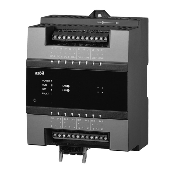
Advanced Remote I/O Module
„ Overview
This product (model RJ-11__W____) is an I/O module
dedicated for Advanced Controller (models
WJ-1101W0000 and WJ-1103W0000), Advanced
Controller for Chiller Units (model WJ-1102Q), and
Advanced Controller for Pump Units (model WJ-1102P).
Up to 20 units of this products can be connected in any
combination to Advanced Controller, Advanced
Controller for Chiller Units, or Advanced Controller for
Pump Units.
„ Features
• Flexible I/O configuration
This product has I/Os, DI, DI + DO, and UIO
(universal I/O), so it allows connections with various
I/Os.
Up to 20 units can be connected in any combination.
• Remote installation
This product can be installed close to the facilities in
the field, away from the Advanced Controller,
Advanced Controller for Chiller Units, or Advanced
Controller for Pump Units.
• Redundancy by ring connection
An Ethernet ring connection allows a fail-safe
network against disconnection.
• Visualized I/O statuses
This product has LEDs to indicate the statuses of the
feedback input from facility equipment and the ON/
OFF output to facility equipment.
Specifications/Instructions
© 2016–2020 Azbil Corporation. All Rights Reserved.
1
AB-7329
Advertisement
Table of Contents

Related Manuals for Azbil RJ-1 Series


Summary of Contents for Azbil RJ-1 Series
- Page 1 An Ethernet ring connection allows a fail-safe network against disconnection. • Visualized I/O statuses This product has LEDs to indicate the statuses of the feedback input from facility equipment and the ON/ OFF output to facility equipment. © 2016–2020 Azbil Corporation. All Rights Reserved.
-
Page 2: Safety Precautions
graphically indicates the prohibited action. (For example, the sign For system design, application design, instructions on the left notifies that disassembly is for use, or product applications, please contact Azbil prohibited.) Corporation. Instructs users to carry out a specific oblig- Azbil Corporation bears no responsibility for any result, atory action to prevent possible danger. - Page 3 AB-7329 CAUTION CAUTION Take anti-lightning surge measures based For wiring, strip the insulation from cables on regional and building characteristics. as specified in this manual. Lightning may cause fire or critical damage If the length of exposed wire is longer than ...
- Page 4 Figure 1. Example system configuration Notes: *1 The Advanced Controller can be connected to an Azbil Supervisory Controller (model BH-101G0_0000) or to a third-party central monitoring unit using BACnet/IP communications. *2 The model WJ-1103W0000 Advanced Controller, the Advanced Controller for Chiller Units, and the Advanced Controller for Pump Units all use BACnet/IPv4 or BACnet/IPv6.
-
Page 5: Connection Conditions
Controller B Figure 2. System Configuration Example The Advanced Controller can be connected to an Azbil Supervisory Controller (model BH-101G0_0000) or to a third-party central monitoring unit using BACnet/IP communications. A redundant network can be configured depending on the requirements of the job. -
Page 6: Optional Parts
AB-7329 „ Model Numbers Model number Description RJ-1 Basic model number for Advanced Remote I/O Module 1600 16 digital inputs, power: 100–240 V AC 1600 8 digital inputs + 8 digital outputs, power: 100–240 V AC 0400 4 universal I/Os (UIO) , power: 100–240 V AC The universal I/O (UIO) can be connected to the Advanced Controller for Chiller Units, Advanced Controller for Pump Units, and model WJ-1103 Advanced ontroller. -
Page 7: Basic Specifications
AB-7329 „ Specifications z Basic specifications Item Rating Power supply Input voltage 100–240 V AC (264 V AC max.) Input frequency 50/60 Hz ± 3 Hz Power consumption Model RJ-1101W1600 13 VA max. Model RJ-1102W1600 14 VA max. Model RJ-1103W0400 16 VA max. -
Page 8: Input/Output Specifications
AB-7329 z Input/output specifications Item Specification Digital input Number of inputs Model RJ-1101W1600 Model RJ-1102W1600 Voltage 24 V DC typ. Current 5 mA DC typ. Connected device output type Dry contact or open collector Dry contact Allowable ON contact resistance 100 Ω... - Page 9 AB-7329 „ Specifications for Wiring Type Item Recommended Rating Maximum Connection Remarks wire length Common Power supply IV/CVV or the 1.25–2.0 mm — Screw equivalent stranded wire terminal block (AWG16–14) Ground IV/CVV or the 1.25–2.0 mm — Screw Ground the equivalent stranded wire terminal block...
- Page 10 AB-7329 „ Dimensions Height: 140 mm, Width: 110 mm, Depth: 80 mm Figure 3. Dimensions (mm) „ Parts Identification LAN1: Ethernet LAN2: Ethernet I/O status LEDs NFC Tag access area Communication status LEDs Product status LEDs I/O status LEDs Power connector Figure 4.
-
Page 11: Installation Location
AB-7329 „ Installation WARNING Install this product in a place, such as a control cabinet, where only the administrator has access to it. Otherwise there is a danger of electric shock. CAUTION Use this product under the operating conditions (for temperature, humidity, power, vibration, shock, ... - Page 12 AB-7329 Duct Model Model WJ-1101W0000 RJ-11_ _W_ _ _ _ WJ-1102_ Duct Duct DIN rail clamps (both sides) Model: 83104567-001 Figure 6. Installation on DIN rail (multiple units) (mm) Figure 7. Installation with screws (single unit) (mm) Note: When multiple units are installed, the maintenance space should be secured as shown in Figure 5, "Installation on DIN rail (multiple units)."...
-
Page 13: Installation Position
AB-7329 z Installation position • This product should be installed upright in the panel. Check that the two DIN holders on the top and Installation of this product on a slant or laid on its bottom of the device are secured on the DIN rail. side is prohibited. - Page 14 AB-7329 „ Wiring • Do not allow the wires to cover the front of this WARNING product. Be sure to ground this product with a ground Draw out the wiring in the vertical direction of the resistance of less than 100 Ω. Improper product, because the front of the product is an area grounding may cause electric shock or for LED displays or for adjusting the product.
- Page 15 AB-7329 (3) Turn the screw above the cable clamp (the hole for (7) Insert the connector into the device. the wire) of the connector to the left with a screw- driver to open the cable clamp. Insert Turn the screw to the left thoroughly to open the insertion slot * Compatible screwdriver blade: 0.6 ×...
- Page 16 AB-7329 <Daisy Chain Topology> 100 m max. LAN2 LAN1 LAN2 LAN1 LAN2 LAN1 • The maximum communication distance is 100 m. To extend the communication distance, connect an industrial switching hub without ring communication (Model NX-SWBN 004_ _) as shown below. This extends the communication distance by 100 m. 100 m max.
- Page 17 AB-7329 <DI Terminals> * If compliance with CE marking is required, provide an EMC filter on the LAN cable that connects to RJ-11_ _W_ _ _ _. Dry contact 83104611-002 83104611-002 83104611-002 or open collector filter filter filter LAN2 LAN1 LAN2 LAN1 LAN2...
- Page 18 AB-7329 <DO Terminals> <UIO Terminals> RJ-1103W0400 I/O terminal FUSE Terminal No. Load Load Load Load AC24V/DC24V UIO1 Terminal No. UIO2 UIO3 UIO4 – Input type Voltage – Current Pt100 Pt100 Pt1000 Pt1k – – Output type Voltage load – Current load Internal circuit Symbol...
- Page 19 AB-7329 Two sample wirings are shown below. (5) When this product is turned off, the loop may be disconnected by the output capacity of the (1) UIO1 Pt100 input, UIO2 Pt1000 input, UIO3 main connected devices. input voltage input, UIO4 main/auxiliary input current In order to secure the current loop, it is necessary input to set the input voltage of this product to 1–5 V and...
- Page 20 AB-7329 „ Indicators z Product status LEDs Item Indicator Color State Description Power supply status POWER Green Power ON Not lit Power OFF Operation mode Green Operating in RUN mode Fast flashing Ethernet congestion detected (flashes every 0.2 s) Slow flashing Operating in DEBUG mode (flashes every 1.4 s) Network status...
- Page 21 AB-7329 z Communication status LEDs Item Indicator Color State Description Communication status LAN1 Green A link is established. Flashing Data is being transmitted and received. Not lit A link is not established. LAN2 Green A link is established. Flashing Data is being transmitted and received. Not lit A link is not established.
- Page 22 AB-7329 „ Handling CAUTION Do not block the ventilation holes of this product. Doing so may cause device failure. IMPORTANT If more than the rated power voltage is accidentally applied to this product, replace the product with a new one for your safety. Failure to do so may cause device failure or cause fire.
- Page 23 Failure to do so may cause electric shock, device failure, or malfunction. Azbil personnel who have been trained on the product will carry out periodic maintenance and parts replacement. Please contact us as necessary. * Refer to the "Model Numbers" section for details on replacement parts.
- Page 24 If compliance with CE marking is required, provide an EMC filter on the LAN cable that connects to RJ-11_ _W_ _ _ _. * BACnet is a trademark of ASHRAE. ® Building Systems Company https://www.azbil.com/ AB-7329 Rev. 5.0 Jul. 2020 Specifications are subject to change without notice. (J: AI-7420 Rev. 4.1)
Need help?
Do you have a question about the RJ-1 Series and is the answer not in the manual?
Questions and answers