Advertisement
Quick Links
Floor Hugger
Series FHLT
Low Profile Electronic
Lift-up Top Platform Scale
Owner's Manual
1943-M032-O1 Rev B
203 E. Daugherty, Webb City, MO 64870 USA
Ph: 417-673-4631 Fax: 417-673-2153
02/15
Printed in USA
www.cardinalscale.com
Technical Support: Ph: 866-254-8261 tech@cardet.com
1943-M032-O1 Rev B Floor Hugger Series FHLT
1
Advertisement

Related Manuals for Cardinal Floor Hugger FHLT Series


Summary of Contents for Cardinal Floor Hugger FHLT Series
- Page 1 Floor Hugger Series FHLT Low Profile Electronic Lift-up Top Platform Scale Owner’s Manual 1943-M032-O1 Rev B 203 E. Daugherty, Webb City, MO 64870 USA Ph: 417-673-4631 Fax: 417-673-2153 02/15 Printed in USA www.cardinalscale.com Technical Support: Ph: 866-254-8261 tech@cardet.com 1943-M032-O1 Rev B ...
- Page 2 1943-M032-O1 Rev B Floor Hugger Series FHLT...
-
Page 3: Table Of Contents
TABLE OF CONTENTS Installation ..........................… 1 Calibration Procedure ........................ 3 Trim Adjustment ....................…....4 Trouble Shooting Guide ......................5 Interconnection Diagram ........…..............6 Raising the Weighbridge Top .......…..............7 Parts Identification ………………………………….…..............8 Your low profile platform scale is designed and manufactured with quality and reliability. Optional inclined ramps may be installed for easy approach and exit of scale. -
Page 5: Installation
INSTALLATION The following section outlines procedures for unpacking and installation of your scale. IMPORTANT: Read this entire section carefully before attempting to unpack or install this scale. Inspect the shipping container for any signs of damage such as exterior dents and scratches. It is the responsibility of the purchaser to file all claims with the shipping company for damages or loss incurred during transit, unless this responsibility has been accepted by the Seller in its proposal. - Page 6 INSTALLATION CONT. FIGURE No. 1 If ramps are to be installed, we recommend raising the scale and positioning the ramps where the foot capture plates are located directly beneath the feet and then gently lowering the scale. Ensure that the feet are captured properly inside the foot plates and that the scale platform does not come in contact with the ramp(s) as this can interfere with weighments taken.
-
Page 7: Calibration Procedure
CALIBRATION PROCEDURE Your scale was factory adjusted to ± .10 percent accuracy at the factory. Minor changes in calibration due to shock and vibration encountered during shipping may necessitate re-calibration. The following procedures require a known test weight, make certain test weight is accurate. -
Page 8: Trim Adjustment
TRIM ADJUSTMENT The purpose of adjusting trim is so the same weight reading will be displayed regardless of where the load is placed on the scale deck. All scales are corner trimmed before leaving the factory. In the event of re-calibration or load cell replacement, follow instructions below to re- trim corners. -
Page 9: Trouble Shooting Guide
TRIM ADJUSTMENT CONT. If two or more load cells must be replaced or scale needs an overall resealing of each corner, these procedures should be followed. 1. Turn all potentiometers clockwise 25 turns. Now turn all potentiometers counterclockwise 1 (one) turn. 2. -
Page 10: Interconnection Diagram
INTERCONNECTION DIAGRAM FIGURE No. 3 1943-M032-O1 Rev B Floor Hugger Series FHLT... -
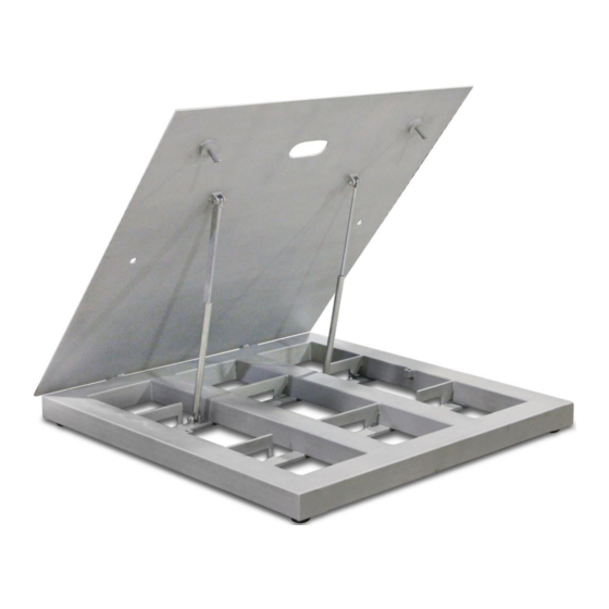
Page 11: Raising The Weighbridge Top
RAISING THE WEIGHBRIDGE TOP Figure No. 4 1. Using safe lifting techniques, raise the weighbridge top from point (1). Do not let it go until it is in the full raised position, point (2). 2. To secure in the raised position, release the prop angle from its loose position and let it rotate downward to engage gas spring. -
Page 12: Parts Identification
PARTS IDENTIFICATION FHLT-544S 1943-M032-O1 Rev B Floor Hugger Series FHLT... - Page 13 PARTS IDENTIFICATION, CONT. FHLT-544S ITEM NO. QTY. PART NUMBER DESCRIPTION 3502-C208-2A JUNCTION BOX, 4 CELL TRIM (REMOTE MOUNT) BOLT HEX HEAD 1/2-20 UNF X 2 1/2” GRADE 5 S.S. 6021-2035 SEE NOTE 1 WEIGHBRIDGE TOP/BOTTOM WELDMENT 593M729 SERIAL TAG 3502-B396-0A LOAD CELL CABLE SB-2500S...
- Page 14 PARTS IDENTIFICATION, CONT. REMOTE TRIM BOX 1943-M032-O1 Rev B Floor Hugger Series FHLT...
- Page 15 PARTS IDENTIFICATION, CONT. REMOTE TRIM BOX ITEM NO. QTY. PART NUMBER DESCRIPTION S.S. ENCLOSURE 3502 -C400-1A 3502-C401-08 S.S. COVER 3502-B403-08 GASKET 3502-C205-0A PC BD. ASSEMBLY SCW PHMS S.S 6-32 x 1/4” 6021-0661 6610-1150 GLAND CONNECTOR SMALL 6610-2248 GLAND CONNECTOR LARGE SCW RHMS S.S.
- Page 16 STATEMENT OF LIMITED WARRANTY WARRANTY TERMS Cardinal Scale Manufacturing Company warrants the equipment we manufacture against defects in material and workmanship. The length and terms and conditions of these warranties vary with the type of product and are summarized below:...
- Page 17 This warranty sets forth the extent of our liability for breach of any warranty or deficiency in connection with the sale or use of our product. Cardinal will not be liable for consequential damages of any nature, including but not limited to loss of profit, delays or expenses, whether based on tort or contract.
- Page 18 1943-M032-O1 Rev B Floor Hugger Series FHLT...
Need help?
Do you have a question about the Floor Hugger FHLT Series and is the answer not in the manual?
Questions and answers