Table of Contents
Advertisement
Quick Links
Advertisement
Table of Contents

Related Manuals for IFM OY51


Summary of Contents for IFM OY51
- Page 1 Operating instructions Measuring light grids (10 mm beam spacing) OY51...
-
Page 2: Table Of Contents
Synchronisation of transmitter and receiver ........11 7.3.1 Synchronisation via ifm Y cable (EY5053 and EY5054) ..... . . 11 7.3.2 Synchronisation via standard sockets . -
Page 3: Preliminary Notes
Measuring light grids (10 mm beam spacing) OY51 1 Preliminary notes You will find instructions, technical data, approvals and further information using the QR code on the unit / packaging or at www.ifm.com. 1.1 Symbols used Instruction Reaction, result Cross-reference LED on LED off... -
Page 4: Safety Instructions
OY51 Measuring light grids (10 mm beam spacing) 2 Safety instructions • The unit described is a subcomponent for integration into a system. – The system architect is responsible for the safety of the system. – The system creator undertakes to perform a risk assessment and to create documentation in accordance with legal and normative requirements to be provided to the operator and user of the system. -
Page 5: Intended Use
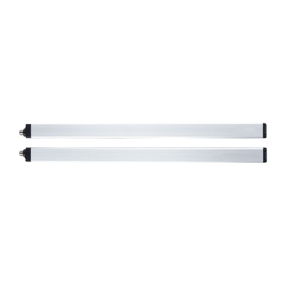
Measuring light grids (10 mm beam spacing) OY51 3 Intended use Transmitter (T) Receiver (R) Detection zone Detection field width Detection field height The OY51 light grids are multi-beam optoelectronic devices and consist of one transmitter and one receiver. -
Page 6: Getting Started
OY51 Measuring light grids (10 mm beam spacing) 4 Getting started For fast set-up, carry out the following steps: u Fix the transmitter and the receiver Installation (Ò / 8). u Connect the receiver to an IO-Link master and establish a connection to the unit. -
Page 7: Function
The IODDs necessary for the configuration of the unit, detailed information about process data structure, diagnostic information, parameter addresses and the necessary information about the required IO-Link hardware and software can be found at www.ifm.com. -
Page 8: Installation
OY51 Measuring light grids (10 mm beam spacing) 6 Installation 6.1 Installation instructions The operating conditions at the mounting location must not affect the functioning of the optoelectronic sensors. Please note especially: • The transmitter and the receiver must not be affected by intensive light sources (emitters, sunlight etc.). -
Page 9: Optical Alignment
Measuring light grids (10 mm beam spacing) OY51 Adjustable brackets can be used to ensure easy optical alignment www.ifm.com. 6.1.2 Optical alignment Transmitter Receiver The LEDs of the receiver help to correctly align the optoelectronic sensors. u Align the transmitter so that the green LED of the receiver lights. - Page 10 OY51 Measuring light grids (10 mm beam spacing) Position of both transmitters next to each other Position transmitter 1 and receiver 2 on top of each other Combination in "L" shape Transmitter Receiver Fig. 1: Possible arrangements...
-
Page 11: Electrical Connection
Synchronisation via ifm Y cable (EY5053 and EY5054) (Ò / 11). The settings are made via IO-Link. 7.3.1 Synchronisation via ifm Y cable (EY5053 and EY5054) The transmitter and the receiver can be synchronised using ifm Y cables (EY5053 or EY5054). They must be wired according to the figure. -
Page 12: Synchronisation Via Standard Sockets
Measuring light grids (10 mm beam spacing) Transmitter Receiver ifm Y cable Connection Alternatively, the receiver can also be connected directly to the IO-Link master using a suitable standard cable. The transmitter can be connected separately via a standard M12 connector (5- pin). - Page 13 Measuring light grids (10 mm beam spacing) OY51 Transmitter Receiver Connection transmitter Connection receiver 24 V DC Ò range 1…10 m 0 V DC Ò range 0…2 m With optical synchronisation, the beam direction cannot be reversed.
-
Page 14: Operating And Display Elements
OY51 Measuring light grids (10 mm beam spacing) 8 Operating and display elements Transmitter LED indication Receiver LED indication 8.1 Transmitter LED states Meaning Green Orange System start Error Transmitter fault diagnostics (Ò / 19) No synchronisation via cable Ready for operation Low range (flashes twice slowly) High range (flashes twice quickly) 8.2 Receiver LED states... -
Page 15: Operation
Measuring light grids (10 mm beam spacing) OY51 9 Operation 9.1 Switching mode (SIO mode) In switching mode, the switching output is controlled according to the parameter setting. 9.2 Operation with IO-Link master If the sensor is connected to an IO-Link master, parameter setting, triggering and data recording can be done completely via IO-Link. -
Page 16: Lbo - Last Beam Occupied
OY51 Measuring light grids (10 mm beam spacing) 9.3.2 LBO – last beam occupied The process value [LBO] indicates the position/number of the last interrupted light beam. The following examples are for illustration purposes. Free light beam [LBO] = 12 [LBO] = 8... -
Page 17: Ncbo - Number Of Consecutive Beams Occupied
Measuring light grids (10 mm beam spacing) OY51 Free light beam [NBO] = 3 [NBO] = 3 Interrupted light beam Number of light beams Detection direction Object NBO: Process value Fig. 5: Example – NBO 9.3.5 NCBO – number of consecutive beams occupied The process value [NCBO] indicates the number of consecutive/contiguous beams occupied. -
Page 18: Technical Data
OY51 Measuring light grids (10 mm beam spacing) 10 Technical data 10.1 Light grid with 10 mm beam spacing Characteristics OY5100 OY5103 OY5106 OY5110 OY5113 OY5116 Total length [mm] 1113 1713 2163 2613 Detection field height 1040 1640 2090 2540 [mm] Number of beams... -
Page 19: Troubleshooting
(Ò / 14)). For a detailed fault description see the following tables. 11.1 Transmitter fault diagnostics Possible cause Troubleshooting Red flashing Internal fault Send device to ifm branch office for repair. 11.2 Fault diagnosis receiver Possible cause Troubleshooting Lit permanently interrupted by a No synchronisation Check the connections and alignment of the light grid. -
Page 20: Maintenance, Repair And Disposal
OY51 Measuring light grids (10 mm beam spacing) 12 Maintenance, repair and disposal • It is recommended to regularly clean the front panes of the transmitter and the receiver. • Clean the unit with a clean, damp cloth. In particularly dusty environments we recommend to spray the cleaned front pane with an antistatic product.
Need help?
Do you have a question about the OY51 and is the answer not in the manual?
Questions and answers