Table of Contents
Advertisement
Quick Links
Advertisement
Table of Contents

Related Manuals for IFM SI0550


Summary of Contents for IFM SI0550
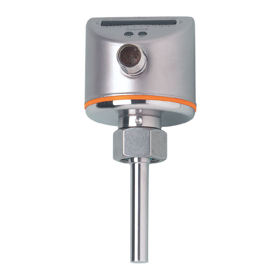
- Page 1 Operating instructions Flow monitors SI0550...
-
Page 2: Table Of Contents
Contents Preliminary note ��������������������������������������������������������������������������������������3 1�1 Symbols used ������������������������������������������������������������������������������������������������3 2 Safety instructions �����������������������������������������������������������������������������������������������3 3 Functions and features ����������������������������������������������������������������������������������������4 3�1 Application area ��������������������������������������������������������������������������������������������4 3�2 Operating conditions ��������������������������������������������������������������������������������������4 3�3 Operating principle flow monitoring ���������������������������������������������������������������4 4 Installation������������������������������������������������������������������������������������������������������������5 4�1 Installation location ����������������������������������������������������������������������������������������5 4�2 Sources of interference in the pipe system ���������������������������������������������������6 4�3 Mounting operation ����������������������������������������������������������������������������������������6 5 Electrical connection ��������������������������������������������������������������������������������������������7 6 Operating and display elements ��������������������������������������������������������������������������7... -
Page 3: Preliminary Note
1 Preliminary note 1.1 Symbols used ► Instruction > Reaction, result […] Designation of buttons, switches or indications → Cross-reference Important note Non-compliance can result in malfunctions or interference� 2 Safety instructions • Please read the product description prior to set-up of the unit� Ensure that the product is suitable for your application without any restrictions�... -
Page 4: Functions And Features
3 Functions and features 3.1 Application area The unit is only suited for use in liquid media� 3.2 Operating conditions The unit reacts very quickly to flow changes of any kind� Therefore, unstable conditions are to be avoided, in particular: • open outlets�... -
Page 5: Installation
• Adapters have to be ordered separately as accessories� A correct fit of the unit and ingress resistance of the connection are only en- sured using ifm adapters� • For small flow rates ifm adapter blocks are available� 4.1 Installation location General • The sensor tip is to be completely... -
Page 6: 4�2 Sources Of Interference In The Pipe System
4.2 Sources of interference in the pipe system Components integrated in the pipes, bends, valves, reductions, etc� lead to turbu- lence of the medium� This affects the function of the unit� Recommendation: Adhere to the distances between sensor and sources of inter- ference: 5...10 x D 3...5 x D... -
Page 7: Electrical Connection
Voltage supply to EN 50178, SELV, PELV� ► Disconnect power� ► Connect the unit as follows: Core colours of ifm sockets: P: programming wire (for remote adjustment) → 8.5) 1 = BN (brown), 2 = WH (white), 3 = BU (blue), 4 = BK (black) Use 4-wire connection cables without a link between pins 2 and 4�... -
Page 8: Set-Up And Settings For Water
7 Set-up and settings for water (For media other than water → 8.1: Low flow adjustment). ► Switch on the supply voltage� > All LEDs light and go out again step by step� During this time the output is closed (if configured as normally open)� The unit is in the operating mode� ►... -
Page 9: 7�2 High Flow Adjustment (Optional)
7.2 High flow adjustment (optional) The unit determines the existing flow as normal flow and adapts the display repre- sentation (all LEDs except the switch point LED light green)� ► Let the normal flow circulate in the installation� ► Press the pushbutton and keep it pressed�... -
Page 10: 8�3 Restore The Factory Setting (Reset)
8.3 Restore the factory setting (reset) ► Press the pushbutton for at least 15 s� > LED 9 lights, after approx� 5 s it flashes� > After approx� 15 s LEDs 0���9 flash orange� ► Release the pushbutton� All settings are reset to the factory setting: - operating area: 5 ���100 cm/s for water - switch point: LED 7 - output function: NO... -
Page 11: Operation
10 Operation After every power on all LEDs light and go out again step by step (during this time the output is closed if configured as normally open)� The unit is then ready for operation� In case of power failure or interruption all settings remain� Operating indicators Green LED bar: Current flow within the represen- tation range�... -
Page 12: Scale Drawing
12 Scale drawing 1: LED bar display 2: set button 3: tightening torque 25 Nm... -
Page 13: Technical Data
EN 61000-4-2 ESD: �������������������������������������������������������������������������������� 4 kV CD / 8 kV AD EN 61000-4-3 HF radiated: �������������������������������������������������������������������������������������� 10 V/m EN 61000-4-4 Burst: ����������������������������������������������������������������������������������������������������� 2 kV EN 61000-4-6 HF conducted: ��������������������������������������������������������������������������������������� 10 V to EN50178, SELV, PELV; The sensor conforms to the standard EN 61000-6-2 More information at www�ifm�com...
Need help?
Do you have a question about the SI0550 and is the answer not in the manual?
Questions and answers