Table of Contents
Advertisement
Quick Links
Advertisement
Table of Contents

Related Manuals for IFM SM9x04 Series


Summary of Contents for IFM SM9x04 Series
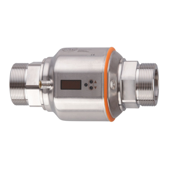
- Page 1 Operating instructions Magnetic-inductive flow meter SM9x04 SM2x04...
-
Page 2: Table Of Contents
Contents 1 Preliminary note ���������������������������������������������������������������������������������������������������4 1�1 Symbols used ������������������������������������������������������������������������������������������������4 1�2 Warning signs used ���������������������������������������������������������������������������������������4 2 Safety instructions �����������������������������������������������������������������������������������������������4 3 Functions and features ����������������������������������������������������������������������������������������5 4 Function ���������������������������������������������������������������������������������������������������������������6 4�1 Processing of the measured signals ��������������������������������������������������������������6 4�2 Direction of flow ���������������������������������������������������������������������������������������������6 4�2�1 Determination of the direction of flow (Fdir) ������������������������������������������6 4�3 Consumed quantity meter �����������������������������������������������������������������������������6 4�4 Empty pipe detection �������������������������������������������������������������������������������������7 4�5 Analogue function ������������������������������������������������������������������������������������������7... - Page 3 10�1�2 Locking / unlocking ���������������������������������������������������������������������������24 10�1�3 Timeout ���������������������������������������������������������������������������������������������24 10�2 Setting the analogue value for temperature ����������������������������������������������24 10�3 Setting the analogue value for volumetric flow ������������������������������������������24 10�4 User settings (optional) ������������������������������������������������������������������������������25 10�4�1 Setting of the standard unit of measurement for temperature ����������25 10�4�2 Setting of the standard unit of measurement for volumetric flow ������25 10�4�3 Configuration of the standard display �����������������������������������������������25 10�4�4 Changing the direction of the flow rate measurement ����������������������25...
-
Page 4: Preliminary Note
1 Preliminary note 1.1 Symbols used ► Instruction > Reaction, result […] Designation of keys, buttons or indications → Cross-reference Important note Non-compliance can result in malfunction or interference� Information Supplementary note� 1.2 Warning signs used CAUTION Warning of personal injury� Slight reversible injuries may result�... -
Page 5: Functions And Features
• For medium temperatures above 50 °C (122 °F) some parts of the housing can heat up to over 65 °C (149 °F)� Moreover, during installation or in case of a fault (e�g� housing damage) media under high pressure or hot media can leak from the system�... -
Page 6: Function
4 Function • The unit detects the flow based on the magnetic-inductive volumetric flow measuring principle� • The unit also detects the medium temperature� • It features an IO-Link interface� • The unit displays the current process value� 4.1 Processing of the measured signals The unit generates 2 output signals according to the parameter setting�... -
Page 7: 4�4 Empty Pipe Detection
- Flow according to the marked flow direction (arrow "flow direction"): meter adds� - Flow against the marked flow direction: meter subtracts� The meter saves the totalled consumed quantity every 10 minutes� After a power failure this value is available as the current meter reading� So the possible data loss can be maximum 10 minutes�... - Page 8 Initial value of the measuring range For non-scaled measuring range (= factory setting) Final value of the measuring range Analogue start point For scaled measuring range Analogue end point Table 1: Definitions [mA] FOU=On 21,5 FOU=OFF cr.UL UL cr.OL -130 -120 [% MEW] [°C]...
-
Page 9: 4�6 Measured Value Damping (Dap)
IO-Link hardware and software can be found at www�ifm�com� ► The memory plug (E30398) must not remain connected to the unit, because it falsifies the analogue output� It must only be connected for... -
Page 10: Installation
5 Installation ► Avoid deposits, accumulated gas and air in the pipe system� The unit can be installed irrespective of the orientation if the following is ensured: - No air bubbles can form in the pipe system� - The pipes are always completely filled� 5.1 Recommended installation locations Example of an optimised installation: ►... -
Page 11: 5�2 Not Recommended Installation Position
► Install in front of or in a rising pipe: F = flow direction With empty pipe detection: ► Install the unit according to figure 1 or 3� 5.2 Not recommended installation position ► Avoid the following installation positions: Directly in front of a falling pipe� In a falling pipe�... -
Page 12: 5�3 Grounding
On the suction side of a pump� F = flow direction 5.3 Grounding If installed in an ungrounded pipe system (e�g� plastic pipes), the unit must be grounded (functional earth)� Ground brackets for the M12 connector are available as accessories (→ www.ifm. com)�... -
Page 13: 5�4 Installation In Pipes
5.4 Installation in pipes The units with a G thread can be installed in the pipes using adapters� Information about the available mounting accessories at www�ifm�com� A correct fit of the unit and ingress resistance of the connection are only ensured using ifm adapters�... -
Page 14: Electrical Connection
6 Electrical connection The unit must be connected by a qualified electrician� The national and international regulations for the installation of electrical equipment must be adhered to� Voltage supply according to EN 50178, SELV, PELV� ► Disconnect power� ► Connect the unit as follows: BK: black BN: brown BU: blue... -
Page 15: Menu
1 to 8: indicator LEDs • LEDs 1-6 = Unit of the currently represented numerical value → 11.1 Reading the process value • LED 7 = current process value in 10 • LED 8 = not used 9: Alphanumeric display, 4 digits •... -
Page 16: 8�2 Main Menu, Extended Functions
8.2 Main menu, Extended functions ↑ Process value display → 8.3 Basic settings → 8.4 Min/max memory – Empty pipe – Simulation... - Page 17 Explanation main menu ASP1 Analogue start value for temperature AEP1 Analogue end value for temperature ASP2 Analogue start value for volumetric flow AEP2 Analogue end value for volumetric flow Extended functions / opening of menu level 2 Explanation extended functions (EF) Restore factory setting IO-L Activate IO-Link communication...
-
Page 18: 8�3 Basic Settings
8.3 Basic settings ↑ Main menu ° ° ... - Page 19 Explanation basic settings (CFG) FOU1 Behaviour of output 1 in case of an error FOU2 Behaviour of output 2 in case of an error Measured value damping / damping constant in seconds Update rate and orientation of the display Uni�F Standard unit of measurement for volumetric flow Uni�T Standard unit of measurement for temperature...
-
Page 20: 8�4 Min/Max Memory - Empty Pipe - Simulation
8.4 Min/max memory – Empty pipe – Simulation ↑ Main menu * Parameters are only displayed for the selection EP�On = On�... -
Page 21: Set
Explanation min/max memory (MEM) HI�F Max� value flow LO�F Min� value flow HI�T Max� value temperature LO�T Min� value temperature Explanation empty pipe (EPD) EP�On Empty pipe detection on / off dEP�E� Delay time empty signal dEP�F Delay time full signal EP�Pr Current measured value of empty pipe detection EP�SP... -
Page 22: Parameter Setting
10 Parameter setting Parameters can be set before installation and set-up of the unit or during opera- tion� If you change parameters during operation, this will influence the function� ► Ensure that there will be no malfunctions in your plant� During parameter setting the unit remains in the operating mode�... -
Page 23: 10�1 Parameter Setting In General
10.1 Parameter setting in general Select parameter 1� Press [Enter] briefly� 2� Press [▲] or [▼] until the requested parameter is displayed. Changing the parameter value 3� Press [Enter] briefly� > The currently set value is displayed� 4� Keep [▲] or [▼] pressed for 1 s. >... -
Page 24: 10�1�1 Switching Between The Menu Levels
10.1.1 Switching between the menu levels Change to the Switching to the next submenu via the parameters [EF], [CFG], submenu [MEM], [EPD] or [SIM]� ► Select a submenu with [▲] or [▼] and switch to the submenu by pressing [Enter]� Back to the process ►... -
Page 25: 10�4 User Settings (Optional)
10.4 User settings (optional) 10.4.1 Setting of the standard unit of measurement for temperature ► Select [Uni�T] and set the unit of measurement: [°C] or [°F]� 10.4.2 Setting of the standard unit of measurement for volumetric flow ► Select [Uni�F] and set the unit of measurement: [Lmin], [m3h], [gpm] or [gph] 10.4.3 Configuration of the standard display ►... -
Page 26: 10�4�7 Activating / Deactivating Empty Pipe Detection
10.4.7 Activating / deactivating empty pipe detection ► Select [EP�On] and set the function: - [OFF] = empty pipe detection deactivated� - [On] = empty pipe detection activated� 10.4.8 Time-delay empty pipe detection ► Select [dEP�E] and set the delay time from 0…30 s, at which the signal should be provided when the pipe is empty�... -
Page 27: 10�5�2 Reading The Min/Max Values For The Temperature
10.5.2 Reading the min/max values for the temperature ► Select [HI�T] or [LO�T] [HI�T] = max� value, [LO�T] = min� value� Delete memory: ► Select [HI�T] or [LO�T]� ► Press [Enter] briefly� ► Keep [▲] or [▼] pressed. > [----] is displayed� ►... -
Page 28: Operation
11 Operation 11.1 Reading the process value The LEDs 1-6 signal which process value is currently displayed� The process value to be displayed as standard (temperature, flow velocity) can be preset� → 10.4.3 Configuration of the standard display� A standard unit of measurement can be defined for the flow velocity (l/min, m /h, gpm or gph) →... -
Page 29: Troubleshooting
Select parameter 1� Press [Enter] briefly 2� Press [▲] or [▼] until the requested parameter is displayed. Display the parameter value 3� Press [Enter] briefly > The currently set value is displayed for 30 s� By pressing [Enter] briefly several times, the display switches between parameter and parameter value�... -
Page 30: Technical Data
• Temperature value > 110 °C or 230 °F PArA Error Parameter setting outside the ► Repeat parameter setting� valid range� MEW = final value of the measuring range 13 Technical data Technical data and scale drawing at www�ifm�com�... -
Page 31: Factory Setting
SMx604: gpm Uni.T SMx004: °C SMx604: °F SELd FLOW 5 l/min EP.On dEP.E dEP.F EP.SP 75 % S.FLW 20 % * S.TMP 20 °C S.Tim 3 min S.On * of the final value of the measuring range More information at www�ifm�com...
Need help?
Do you have a question about the SM9x04 Series and is the answer not in the manual?
Questions and answers