Advertisement
Quick Links
Advertisement

Related Manuals for IFM SMF 2 Series


Summary of Contents for IFM SMF 2 Series
- Page 1 Operating instructions Magnetic-inductive flow meter SMFx2x...
- Page 2 SMFx2x Magnetic-inductive flow meter Contents Preliminary note ............. Symbols used .
- Page 3 Magnetic-inductive flow meter SMFx2x 10.4.13 Totaliser reset ............49 10.4.14 Counting method of the totalisers .
- Page 4 SMFx2x Magnetic-inductive flow meter 1 Preliminary note You will find instructions, technical data, approvals and further information using the QR code on the unit / packaging or at documentation.ifm.com. 1.1 Symbols used Requirement Instructions Reaction, result [...] Designation of keys, buttons or indications...
- Page 5 Magnetic-inductive flow meter SMFx2x 2 Safety instructions • The unit described is a subcomponent for integration into a system. – The system architect is responsible for the safety of the system. – The system architect undertakes to perform a risk assessment and to create documentation in accordance with legal and normative requirements to be provided to the operator and user of the system.
- Page 6 SMFx2x Magnetic-inductive flow meter 2.1 Cybersecurity Installation The device is suitable for operation in a secure environment according to IEC 62443-1-1. The device was designed for operation behind a firewall. u Carry out a risk assessment of the system according to IEC 62443-1-1. u Take measures to ensure physical security.
- Page 7 Magnetic-inductive flow meter SMFx2x 3 Intended use The unit monitors liquid media. The device measures the flow velocity, the volume flow (consumed quantity / time), the consumed quantity, the medium temperature and the conductivity. 3.1 Application area Use in hygienic areas for liquid media with a conductivity of ≥ 5 µS/cm. This is a class A product.
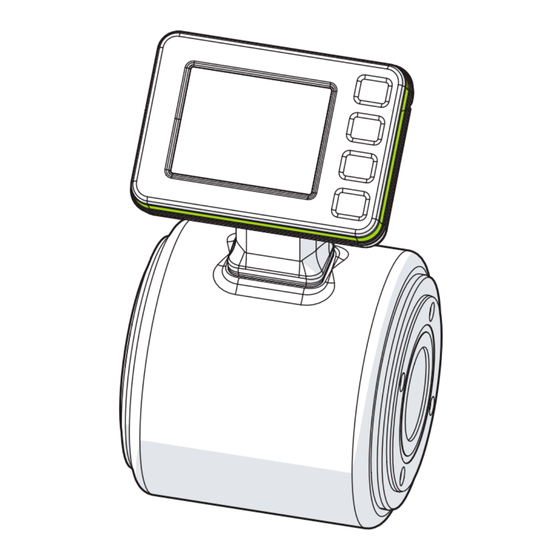
- Page 8 Magnetic-inductive flow meter 4 Function Fig. 1: Product description SMFxxx device (measuring circuit and display) Exxxxx seal, can be ordered separately from www.ifm.com Exxxxx process adapter, can be ordered separately from www.ifm.com Operating status LED (LED ring) Temperature-measuring electrode in the measuring pipe...
- Page 9 IO-Link is a communication system for connecting intelligent sensors and actuators to automation systems. IO-Link is standardised in the IEC 61131-9 standard. General information on IO-Link at io-link.ifm Input Output Device Description (IODD) with all parameters, process data and detailed descriptions of the device at...
- Page 10 SMFx2x Magnetic-inductive flow meter IO-Link offers the following advantages: • Interference-free transmission of all data and process values • Parameter setting in the running process or presetting outside the application • Parameters for identifying the connected devices in the system •...
- Page 11 Magnetic-inductive flow meter SMFx2x 5 Mounting CAUTION If the medium temperature is above 50 °C (122 °F), parts of the housing can increase in temperature to over 65 °C (149 °F). w Risk of burns. u Protect the housing against contact with flammable substances and unintentional contact.
- Page 12 SMFx2x Magnetic-inductive flow meter When installed in a vertical position, the electrodes for flow measurement (1) should be in the same plane. Any deviation from this can lead to measurement inaccuracies. Fig. 3: Orientation of the flow- measuring electrodes Fig. 4: Recommended and non-recommended installation positions Flow direction (Ò / 45) The unit can be installed independently of the orientation if the following is ensured: - No air bubbles can form in the pipe system.
- Page 13 Magnetic-inductive flow meter SMFx2x Avoid the following installation positions: • At the highest point of the pipe system. • Directly upstream of a free pipe spout in a downpipe • On the suction side of a pump. Installation in the vicinity of control valves: u Install the device upstream of the control valve in the direction of flow: Installation in the vicinity of pumps: u Install the device downstream of the pump in the direction of flow to avoid negative pressure in the...
- Page 14 5.4 Process connection Using process adapters the unit can be adapted to different process connections. ifm offers hygienic process adapters and seals made of the materials FKM, EPDM and VMQ, which must be ordered separately as accessories. Information about available accessories at documentation.ifm.com.
- Page 15 Magnetic-inductive flow meter SMFx2x Fig. 6: Installation of the device in the process Process adapters Seal Protective cap Sensor Procedure: The sensor, the process adapters and the seals must be ordered separately. Additional instructions for the respective process adapters are described in the following chapters.
- Page 16 Ø A: Outer diameter of the adapter Ø B: Inner diameter of the adapter ifm electronic offers clamp adapters in compliance with ISO 2852, DIN 32676-A (DIN) and DIN 32676- C (ASME BPE) for various pipe standards: Nominal ifm adapters Dimensions in mm (Ò...
- Page 17 Ø A: Outer diameter of the adapter Ø B: Inner diameter of the adapter ifm electronic offers welding adapters in compliance with EN 10357 series A (DIN), C (ASME BPE) and D (SMS) for various pipe standards: Nominal ifm adapters Dimensions in mm (Ò Fig-...
- Page 18 SMFx2x Magnetic-inductive flow meter ifm adapt- Nominal Dimensions in mm (Ò Fig- Type ers availa- Applicable pipe standard width ure above) SMF6xx DN80 SMF7xx DN100 Tab. 6: Welding adapter EN 10357 series C (ASME BPE)
- Page 19 Installation depth of sensor + adapter Ø A: Outer diameter of the adapter Ø B: Inner diameter of the adapter ifm electronic offers screw adapters in compliance with DIN 11851 (pipe fitting) and SMS 1145 for various pipe standards: Nominal ifm adapters Dimensions in mm (Ò Figure...
- Page 20 Installation depth of sensor + adapter Ø A: Outer diameter of the adapter Ø B: Inner diameter of the adapter ifm electronic offers aseptic flange adapters in compliance with DIN 11864-2A: Nominal ifm adapters Dimensions in mm (Ò Figure Type Applicable pipe standard...
- Page 21 Magnetic-inductive flow meter SMFx2x Fig. 11: Process connection in compliance with 3-A Minimum gradient u To allow the medium to flow out of the process adapter, mount the device in the following installation position: • Vertical installation in a rising pipe (Ò...
- Page 22 1. The operating connector is for the operation of the device. 2. The service connector must only be used by ifm staff when the device is being serviced. u Cover the connectors with protective caps when they are not in use. Protective caps can be ordered individually from documentation.ifm.com.
- Page 23 Magnetic-inductive flow meter SMFx2x Assignment 4 (OUT1) • Pulse signal totaliser • Switching signal totaliser • Switching signal diagnosis • IO-Link • OFF (output switched to high impedance) 2 (OUT2/InD) • Pulse signal totaliser • Switching signal totaliser • Analogue signal flow •...
- Page 24 SMFx2x Magnetic-inductive flow meter 7 Operating and display elements Fig. 14: Operating and display elements TFT-Display 3.5”: Shows 1 to 4 process values (Ò Display layout / 54). Title line: Describes the status of the device (normal operation, warning messages, error messages). Operating status LED (LED ring): Changes colour to signal the status of the device. (Ò...
- Page 25 Magnetic-inductive flow meter SMFx2x If the device measures a high internal temperature, the display brightness is automatically adjusted: Internal temperature > 75 °C: brightness is reduced to 25%. Internal temperature ≥ 90 °C: display is automatically switched off.
- Page 26 Service Transition to the following submenus and display screens: • [SIM]: Simulation (Ò Submenus / 32). • [O.CFG]: Configuration (Ò / 59). • [QR]: Shows the QR codes with links to the data sheet, the operating instructions and the certificate at www.ifm.com (Ò Documents / 60).
- Page 27 Magnetic-inductive flow meter SMFx2x 8.2 Submenus The displayed parameters change when the factory setting is changed. The following menu displays show the maximum available parameters. Output 1 menu [OUT1]: OUT1 [OUT1] dOU│ImP│OFF ImPS1 dFu1 ---- dir.F│FD ImPR1 YES│No Parameter Explanation Output function for output OUT1 Diagnostic function Totaliser function Output off...
- Page 28 SMFx2x Magnetic-inductive flow meter Output 2 menu [OUT2]: OUT2 [OUT2] In.D│dOU│ImP│ │OFF SEL2 FLOW│TEMP│COND dFu2 dir.F│FD ASP2 ---- ImPS2 ---- DIn2 HIGH +EDG AEP2 ImPR2 ---- YES│No -EDG FOU2 Parameter Explanation Output function for output OUT2 In.D Totaliser reset via external signal Diagnostic function Totaliser function Analogue function...
- Page 29 Magnetic-inductive flow meter SMFx2x Totaliser menu [TOTL]: TOTL [TOTL] rTo1 rES.T│Weeks│Days│Hours│OFF rTo2 rES.T│Weeks│Days│Hours│OFF FPro1 -+│0+│++│-0 FPro2 -+│0+│++│-0 i.TOT VTOTL1│VTOTL2│Vol.L Parameter Explanation rTox Setting for the totaliser reset: Manual reset (= rES.T), time-controlled reset (= weeks, days, hours) or reset via overflow (= OFF) FProx Counting method of the totaliser: consideration of the direction of flow i.TOT...
- Page 30 FD.On On│OFF OFF│ECO│ECO+ date ---- APPL│BtB [CFG] * The options depend on the device type, see technical data at documentation.ifm.com. Parameter Explanation uni.F Standard unit of measurement for flow uni.T Standard unit of measurement for temperature uni.C Standard unit of measurement for conductivity dAP.F...
- Page 31 Magnetic-inductive flow meter SMFx2x Parameter Explanation FD.On Activate or deactivate fluid detection indication via the operating status LED. If [On] is set, the LED flashes red if no fluid is detected. Energy-saving mode [ECO] or [ECO+] or energy-saving mode [OFF]. Setting options for [ECO] and [ECO+]: [E.dib] = display brightness and [E.LED] = LED ring.
- Page 32 SMFx2x Magnetic-inductive flow meter Simulation [SIM] menu: S.FLW [SIM] ---- S.TMP ---- S.CND ---- S.Tim ---- S.On ---- S.Diag n.DIA│FD.On Parameter Explanation S.FLW Simulated flow value in simulation mode S.TMP Simulated temperature value in simulation mode S.CND Simulated conductivity value in simulation mode S.Tim Duration of the simulation in minutes S.On...
- Page 33 Magnetic-inductive flow meter SMFx2x 9 Set-up After power on and expiry of the power-on delay time, the unit is in the normal operating mode. It carries out its measurement and evaluation functions and generates output signals according to the set parameters. During the power-on delay time, the outputs are in the following status according to the set parameters: •...
- Page 34 SMFx2x Magnetic-inductive flow meter 10 Parameter setting Parameter setting can be carried out via the IO-Link interface or via the operating elements on the unit. Parameters can be set before installation or during operation. If you change parameters during operation, this will influence the function of the plant. u Ensure that there will be no malfunctions in your plant.
- Page 35 SMFx2x 10.2 Parameter setting via IO-Link The device parameters can be set via the IO-Link interface in the following ways, for example: • Parameter setting via a suitable parameter setting software, e.g. ifm moneo|configure • Parameter setting via a PLC •...
- Page 36 SMFx2x Magnetic-inductive flow meter [mA] FOU=On 21,5 20,5 FOU=OFF cr.UL UL OL cr.OL -130 -120 -100 [% MEW] 150 160 [°C] Fig. 16: Characteristics of the analogue output according to the standard IEC 60947-5-7 Analogue signal MAW: Initial value of the measuring range Measured value MEW: Final value of the measuring range...
- Page 37 Magnetic-inductive flow meter SMFx2x 10.3.2.1 Switching signal for flow direction A flow direction change can be monitored by providing a switching signal. An arrow with the text “flow direction” on the device indicates the positive flow direction. The direction of the flow measurement can be reversed using the parameter [Fdir]. Flow direction (Ò / 45).
- Page 38 SMFx2x Magnetic-inductive flow meter Temperature electrode Fig. 18: Fluid detection Medium detected Medium not detected Parameter setting via the device keys: Switching signal for fluid detection u Go to menu [Settings] > [OUTx]. u Select [oux] and set [dOU]. u Select [dFU] and set [FD]. u Go to ...
- Page 39 Magnetic-inductive flow meter SMFx2x • The accuracy of the consumed quantity measurement depends on the accuracy of the flow measurement. • A switching signal or pulse signals can be provided for consumed quantity monitoring: – See Switching signal totaliser (Ò / 39) –...
- Page 40 SMFx2x Magnetic-inductive flow meter Minimum pulse value [ImPS1] 2 ml 2 ml 4 ml 5 ml 9 ml Tab. 13: Lower setting range for [ImPS1] by device Pulse signals are not available via the IO-Link interface. Parameter setting via unit keys: Pulse signal totaliser ü...
- Page 41 Magnetic-inductive flow meter SMFx2x • [Window Mode] The switching signal channel changes to the active state depending on the process data value (PDV). The active state is above the switch point in [Single Point Mode] and [Two Point Mode] and within the window section in [Window Mode].
- Page 42 SMFx2x Magnetic-inductive flow meter The hysteresis will be ignored in Two Point Mode. high high (TP2) (TP1) (TP2) (TP1) Fig. 23: [Two Point Mode] / [High active] Fig. 24: [Two Point Mode] / [Low active] SP1: Switch point 1 SP1: Switch point 1 SP2: Switch point 2 SP2:...
- Page 43 Magnetic-inductive flow meter SMFx2x u Select [oux] and set [OFF]. 10.4 Application configuration The chapter describes the setting options for adaptation to your specific application. 10.4.1 Standard unit of measurement A unit of measurement can be selected with which the process value is shown in the display by default.
- Page 44 SMFx2x Magnetic-inductive flow meter 10.4.3 Error behaviour of the analogue output The behaviour of the analogue output OUT2 in the event of an error can be set via the parameter [FOU2]. The following signals are output in the event of an error: [FOU2] [SEL2] Output signal...
- Page 45 Magnetic-inductive flow meter SMFx2x • the digital switching signal for flow • the analogue signal for flow • the consumed quantity monitoring (switching or pulse signal for flow) • the memory values for minimum and maximum flow The accuracy indicated in the data sheet applies to the factory-set LFC value. If a lower LFC value is set, the accuracy of the sensor will decrease.
- Page 46 SMFx2x Magnetic-inductive flow meter If there is a systematic deviation between the measured value and the actual process value, this measurement inaccuracy can be corrected using the correction factor [coF.x]. • [coF.F] = correction factor for measuring flow • [coF.C] = correction factor for measuring conductivity The unit for [coF.F] and [coF.C] is the set standard unit of measurement for the process values flow and conductivity (Ò...
- Page 47 Magnetic-inductive flow meter SMFx2x The slope modification of the measurement characteristic is indicated in per cent. The factory setting is [CGA] = 100%. After a change the calibration can be reset to factory setting. 150 % 100 % 50 % Fig. 28: Calibration of the measurement characteristic Measured value Measurement characteristic at factory setting Measurement characteristic after offset by +50%...
- Page 48 SMFx2x Magnetic-inductive flow meter 10.4.10.1 Determination of the temperature coefficient tempco 1. Set the parameters [T.Cmp] and [dAP] to zero: [T.Cmp] = [0], [dAP] = [0]. u Write the changed values to the sensor. 1. Adjust the medium to 25 °C, for example, and take down the value of the conductivity after 2 min.
- Page 49 Magnetic-inductive flow meter SMFx2x The [ECO] parameter can be used to select between two energy-saving levels: [ECO] and [ECO+]. The energy-saving mode is switched off via the [OFF] setting. Both energy-saving modes can be configured via the parameters [E.dib] and [E.LED]. In [ECO+] mode, the measuring rate can also be set.
- Page 50 SMFx2x Magnetic-inductive flow meter 3. Reset via external signal: u Go to menu [Settings] > [OUT2]. u Select [ou2] and set digital input: [In.D]. u Select [DIn2] and set the reset signal: • [HIGH]: reset for high signal • [LOW]: reset for low signal •...
- Page 51 Magnetic-inductive flow meter SMFx2x FPro1 / FPro2 = 0 + – Q FPro1 / FPro2 = – 0 – Q FPro1 / FPro2 = – + – Q FPro1 / FPro2 = + + – Q Fig. 29: taking account of the volumetric flow direction when totalling the consumed quantity volumetric flow quantity in positive direction volumetric flow quantity in negative direction volumetric flow quantity absolute (= sum of negative and positive volumetric flow)
- Page 52 SMFx2x Magnetic-inductive flow meter If IO-Link data storage is activated, this triggers a parameter update in the master. This writes the parameters configured in the master to the device again. An application reset may therefore be ineffective. [BtB] = Back to Box The following is reset to the factory setting: •...
- Page 53 Magnetic-inductive flow meter SMFx2x 10.5.2 Display rotation Use the parameter [diS.R] to rotate the text in the display clockwise for better readability. Selectable values: • 0° (not rotated) • 90° • 180° • 270° 10.5.2.1 Parameter setting via unit keys: display rotation u Go to the [Display] menu.
- Page 54 SMFx2x Magnetic-inductive flow meter 10.5.5 Display layout The standard display can be set via the parameter [diS.L]. This function is only available via the IO-Link interface or the wizard. A maximum of four of the following display screens can be selected: •...
- Page 55 Magnetic-inductive flow meter SMFx2x Permanent colour selection The font colour is permanently white on a black background: [coL.F] = [coL.T] = [coL.C] = Font colour 107.05 [bk/wh] White l / min Flow Fig. 31: Example: [coL.F] = [bk/wh] Colour change depending on freely definable limit values If the measured value is within the limits of [cFL.x]…[cFH.x], the following applies depending on the parameter selection: [coL.F] =...
- Page 56 SMFx2x Magnetic-inductive flow meter • Internal temperature (Ò / 57) • Operating status LED (Ò / 57) • Event history (Ò / 58) 10.6.1 Read totaliser values For the totalisers VTOTL1 and VTOTL2 and the lifetime totaliser Vol.L, the following values can be read at any time on the display or via the IO-Link interface: Totaliser values VTOTL1 and VTOTL2 •...
- Page 57 Magnetic-inductive flow meter SMFx2x u [Lo.x] or [Hi.x] > select [Reset] and [Yes]. w The memory for process value x (F = flow, T = temperature or C = conductivity) is reset. 10.6.3 Operating hours counter The operating hours since the first set-up are stored by the unit. The current value can be read from the unit’s display or via the IO-Link interface.
- Page 58 SMFx2x Magnetic-inductive flow meter LED mode Operating status LED The LED ring is permanently off. Noti The LED ring is off during normal operation. The LED ring is only on for diagnostics (blue or red). PdOU* The LED ring is controlled via the IO-Link process data interface PD OUT. PArA* The LED ring is permanently lit in the set colour (red, green, blue or yellow).
- Page 59 Magnetic-inductive flow meter SMFx2x 10.7.1.1 Reading via the device keys: Device information u Go to [Device information] menu and read the device information. 10.7.2 Configuration All the device settings can be shown on the device display via the Service menu. The parameters, currently set values and original factory settings are shown in a list.
- Page 60 The device offers a function for reading binary data from the device as one large file (BLOB = Binary Large Object). The data is exported as a CSV file. This requires a software tool (e.g. ifm moneo) that supports the IO-Link BLOB interface. The CSV file contains the following logbook information: •...
- Page 61 Magnetic-inductive flow meter SMFx2x 10.7.6 Optical localisation The sensor can be located remotely in the system via the IO-Link interface. When using the command, the LED ring flashes green. 10.7.7 Lock / unlock The unit can be locked electronically to prevent unauthorised setting. This lock prevents the settings from being changed via the keys on the unit.
- Page 62 SMFx2x Magnetic-inductive flow meter 11 Operation After power on and expiry of the power-on delay time, the unit is in the normal operating mode. It carries out its measurement and evaluation functions and generates output signals according to the set parameters.
- Page 63 If a process value fails, the other process values are still available. Exception: If the process value for flow fails, no other process values are output. Additional diagnostic functions are available via IO-Link Ò IO-Link interface description at documentation.ifm.com. 12.1 Warning messages Display...
- Page 64 SMFx2x Magnetic-inductive flow meter 12.2 Error messages Display Operating Status* IO-Link event Problem Corrective measures Process value status LED Title line display u Replace the Device error ---- 0x5000 Hardware error in the device / de- device. vice is defective. Component All process values red flashing 0x5010...
- Page 65 A defective display unit can be replaced with a new one by the customer. A display unit cannot be replaced by an electronic unit without a display, but only by an identical display unit. Information about suitable accessories at www.ifm.com.
- Page 66 SMFx2x Magnetic-inductive flow meter Fig. 33: Replacing the display unit M4 screws Seal Connector for electrical connection CAUTION Risk of electric shock w Touching live parts can result in personal injury. u Ensure that the power supply is disconnected before installing or removing the display. ATTENTION Damage to the device when replacing the display unit w Improper replacement will invalidate the warranty.
- Page 67 Magnetic-inductive flow meter SMFx2x 14 Factory settings General settings: Parameter Factory setting uni.F SMFxx0: m³/h SMFxx1: gpm uni.T SMFxx0: °C SMFxx1: °F uni.C µS/cm FPro1 FPro2 rTo1 rTo2 dAP.F SMF320: 0.3 m³/h SMF321: 1.4 gpm SMF420: 0.6 m³/h SMF421: 2.6 gpm SMF520: 1.2 m³/h SMF521: 5.5 gpm SMF620: 1.8 m³/h...
Need help?
Do you have a question about the SMF 2 Series and is the answer not in the manual?
Questions and answers