Table of Contents
Advertisement
Quick Links
Advertisement
Table of Contents

Related Manuals for IFM SD1540


Summary of Contents for IFM SD1540
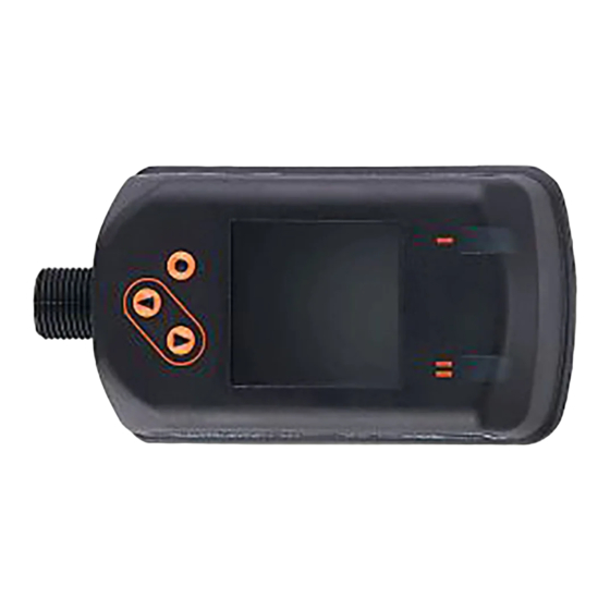
- Page 1 Operating instructions Flow meter compressed air SD1540...
-
Page 2: Table Of Contents
Contents 1 Preliminary note ���������������������������������������������������������������������������������������������������4 1�1 Symbols used ������������������������������������������������������������������������������������������������4 1�2 Warnings used �����������������������������������������������������������������������������������������������5 2 Safety instructions �����������������������������������������������������������������������������������������������5 3 Functions and features ����������������������������������������������������������������������������������������6 4 Function ���������������������������������������������������������������������������������������������������������������6 4�1 Processing of the measured signals ��������������������������������������������������������������6 4�2 Switching output ��������������������������������������������������������������������������������������������7 4�3 Analogue output ���������������������������������������������������������������������������������������������8 4�4 Consumed quantity monitoring ��������������������������������������������������������������������10 4�4�1 Meter reading �������������������������������������������������������������������������������������10 4�4�2 Counter reset ������������������������������������������������������������������������������������10... - Page 3 8�6 Submenu CFG ���������������������������������������������������������������������������������������������28 8�7 Submenus MEM, DIS ����������������������������������������������������������������������������������30 8�8 Submenus COLR, SIM ��������������������������������������������������������������������������������32 9 Set-up ����������������������������������������������������������������������������������������������������������������34 10 Parameter setting ��������������������������������������������������������������������������������������������34 10�1 Parameter setting in general ���������������������������������������������������������������������35 10�1�1 Select submenu ��������������������������������������������������������������������������������35 10�1�2 Change to the process value display (RUN mode) ��������������������������35 10�1�3 Lock / unlock �������������������������������������������������������������������������������������36 10�1�4 Timeout ���������������������������������������������������������������������������������������������36 10�2 Settings for volumetric flow monitoring ������������������������������������������������������36...
-
Page 4: Preliminary Note
13 Maintenance, repair and disposal ��������������������������������������������������������������������47 14 Factory setting �������������������������������������������������������������������������������������������������48 1 Preliminary note Detailed instructions, technical data, approvals and other information via the QR code on the unit / on the packaging or at www�ifm�com� 1.1 Symbols used ► Instructions >... -
Page 5: 1�2 Warnings Used
1.2 Warnings used CAUTION Warning of personal injury� Slight reversible injuries may result� 2 Safety instructions • The device described is a subcomponent for integration into a system� - The manufacturer is responsible for the safety of the system� - The system manufacturer undertakes to perform a risk assessment and to create a documentation in accordance with legal and normative requirements to be provided to the operator and user of the system�... -
Page 6: Functions And Features
3 Functions and features The unit monitors the standard volume flow of compressed air in industrial use� It detects the 5 process variables flow velocity, volumetric flow quantity, consumed quantity, medium temperature and pressure� All indications apply to standard volume flow to DIN ISO 2533, i�e� volume flow at 1013 mbar, 15 °C and 0 % relative air humidity�... -
Page 7: 4�2 Switching Output
- switching signal for temperature limit - switching signal for pressure limit - switching signal for preset counter - switching signal for quantity meter - analogue signal for volumetric flow quantity - analogue signal for temperature - analogue signal for pressure - input for external counter reset signal (InD) - OFF (output switched to high impedance) 4.2 Switching output... -
Page 8: 4�3 Analogue Output
When set to the window function, the upper limit value (FH) and the lower limit value (FL) have a fixed hysteresis of 0�25 % of the final value of the measuring range� This keeps the switching status of the output stable if the volumetric flow varies slightly�... - Page 9 [mA] FOU=On 21,5 20,5 FOU=OFF cr�UL UL cr�OL [% MEW] [bar] [°C] [°F] Fig� 1: Characteristics of the analogue output according to the standard IEC 60947-5-7� analogue signal measured value (volumetric flow, temperature or pressure) detection zone display range measuring range scaled measuring range flow pressure...
-
Page 10: 4�4 Consumed Quantity Monitoring
4.4 Consumed quantity monitoring The unit has an internal quantity meter (totaliser)� It continuously sums up the consumed quantity and provides this process value both on the display and via the IO-Link interface� Pulse signals or a switching signal (preset counter) can be used to monitor the consumed quantity�... -
Page 11: 4�4�3 Consumed Quantity Monitoring Via Pulse Signals
4.4.3 Consumed quantity monitoring via pulse signals Every time the flow rate set with [ImPS] has been reached (pulse value), the output provides a pulse signal� OUT1 and OUT2 cannot be used simultaneously for the pulse output� Pulse signals are not available via the IO-Link interface� 4.4.4 Consumed quantity monitoring via preset counter When the flow rate set under [ImPS] has been reached, the output provides a switching signal�... -
Page 12: 4�5 Measured Value Damping
4.5 Measured value damping The damping time [dAP�F] und [dAP�P] allows to set after how many seconds the output signal has reached 63 % of the final value if the flow value / the pressure value changes suddenly� The set damping time stabilises the switching outputs, the display and the process value transfer via the IO-Link interface�... -
Page 13: 4�8 Colour Of The Characters In The Display
4.8 Colour of the characters in the display The colour of the characters in the display can be set via the parameter [coL�x]: • Permanent definition of the display colour: - bk/wh (black/white) - yellow - green - red • Colour change from red to green or vice versa (Fig� 2): - r-cF (red display colour between the limits cFL���cFH) - G-cF (green display colour between the limits cFL���cFH) cFL = lower limit... -
Page 14: 4�9 Io-Link
The IODDs necessary for the configuration of the unit, detailed information about process data structure, diagnostic information, parameter addresses and the necessary information about the required IO-Link hardware and software can be found at www�ifm�com� 4.9.1 Additional functions via IO-Link • Noise-immune signal transmission without measured value losses�... -
Page 15: Installation
5 Installation CAUTION If the medium temperature is above 50 °C (122 °F), parts of the housing can increase in temperature to over 65 °C (149 °F)� > Risk of burns� ► Protect the housing against contact with flammable substances and unintentional contact�... -
Page 16: 5�3 Installation Position
5.3 Installation position • Permitted installation positions: pipe length vertical, any position (fig� 1, 2); pipe length horizontal, unit vertical (fig� 3, 4); unit on side, pipe length right (fig� 5)� • Avoid the installation position in fig� 6 (unit on side, pipe length left)� If the flow rate is low, the specified measurement accuracy cannot be adhered to�... -
Page 17: 5�4 Installation Example Using The Process Adapter E40195
5.4 Installation example using the process adapter E40195 For an ideal alignment of the sensor's measuring probe to the direction of flow of the medium (fig� 4), observe the following notes on welding of the E40195 process adapter into the pipe: ►... -
Page 18: Electrical Connection
6 Electrical connection The device must be connected by a qualified electrician� Voltage supply according to EN 50178, SELV, PELV� ► Disconnect power� ► Connect the unit as follows: OUT2 OUT1 Colours to DIN EN 60947-5-2 BK: black; BN: brown; BU: blue; WH: white Connection •... - Page 19 Circuit examples: 2 x positive switching 2 x negative switching 1 BN 1 BN 2 WH 2 WH 4 BK 4 BK 3 BU 3 BU 1 x positive switching / 1 x analogue 1 x negative switching / 1 x analogue 1 BN 1 BN 2 WH...
-
Page 20: Operating And Display Elements
7 Operating and display elements 1 and 2: Switching status LEDs • LED 1 = switching status OUT1 (on if output 1 is switched) • LED 2 = switching status OUT2 (on if output 2 is switched) 3: TFT display •... -
Page 21: Menu
8 Menu 8.1 Process value display (RUN) It is possible to select three process value indications during operation: ► Press [▲] or [▼]. > The display changes between the standard indication and two other views� > After 30 s, the device returns to the standard display� Running���... -
Page 22: 8�2 Main Menu
8.2 Main menu Process value display (RUN) ImPS1 ImPR1 ASP2 ImPS2 DIn2 AEP2 ImPR2 rES, rTo, Info, OUT1, OUT2, CFG, MEM, DIS, COLR, SIM Explanation of the parameters → 8.4 Submenu OUT1 and → 8.5 Submenu OUT2 The displayed parameters change when the factory setting in submenu OUT1 and OUT2 is changed�... -
Page 23: 8�3 Extended Functions
8.3 Extended functions (EF) Main menu Parameter Explanation and setting options - - - - restore factory setting rES.T reset of the totaliser 2 h 3 h 4 h 5 h ... Info display device information - - - - Info OUT1 configuration output 1... -
Page 24: 8�4 Submenu Out1
8.4 Submenu OUT1 Main menu SEL1 FLOW TEMP PRES Hno Hnc Fno Fnc ImP OFF Info OUT1 ImPS1 OUT2 ImPR1 OUT1 FOU1 OU On OFF COLR... - Page 25 Explanations submenu OUT1 Parameter Explanation and setting options SEL1 standard unit of measurement for evaluation by OUT1: FLOW (volumetric flow) or TEMP (temperature) or PRES (pressure) output function for OUT1: • flow Hno, Hnc, Fno, Fnc, ImP, OFF • temperature: Hno, Hnc, Fno, Fnc, OFF •...
-
Page 26: 8�5 Submenu Out2
8.5 Submenu OUT2 Main menu Info OUT1 SEL2 FLOW TEMP PRES OUT2 Hno Hnc Fno Fnc In.D ASP2 ImPS2 DIn2 AEP2 ImPR2 COLR OUT2 FOU2 OU On OFF The displayed parameters change when the factory setting in submenu OUT2 is changed�... - Page 27 Explanation submenu OUT2 Parameter Explanation and setting options SEL2 standard measured variable for evaluation by OUT2: FLOW (volumetric flow) or TEMP (temperature) or PRES (pressure) output function for OUT2: • flow Hno, Hnc, Fno, Fnc, I, ImP, OFF • temperature: Hno, Hnc, Fno, Fnc, I, OFF •...
-
Page 28: 8�6 Submenu Cfg
8.6 Submenu CFG Main menu uni.F /min m/s ft /h ft /min ft/s uni.T °C °F Info uni.P kPa bar psi OUT1 - - - dAP.F OUT2 - - - dAP.P PnP nPn - - - - - - - - - rEF.P COLR - - -... - Page 29 Explanation submenu CFG Parameter Explanation and setting options uni�F standard unit of measurement for volumetric flow uni�T standard unit of measurement for temperature uni�P standard unit of measurement for pressure dAP�F measured value damping for volumetric flow dAP�P measured value damping for pressure output logic Indication of the internal pipe diameter in mm low flow cut-off...
-
Page 30: 8�7 Submenus Mem, Dis
8.7 Submenus MEM, DIS Main menu Lo�F ��� Hi�F ��� ��� Lo�T Info Hi�T ��� OUT1 ��� Lo�P OUT2 Hi�P ��� diS�L L2�Temp L2�Pres L2.Totl L3�TP COLR diS�U d1 d2 d3 diS�R 0 90 180 270 diS�B 25 50 75 100 OFF... - Page 31 Explanation submenu MEM Parameter Explanation and setting options Lo�F Minimum value of the flow value measured in the process (flow volume or flow velocity) Hi�F Maximum value of the flow value measured in the process (flow volume or flow velocity) Lo�T Minimum value of the temperature measured in the process Hi�T...
-
Page 32: 8�8 Submenus Colr, Sim
8.8 Submenus COLR, SIM Main menu coL�F bk/wh red green yellow r-cF G-cF - - - cFH�F - - - cFL�F coL�T bk/wh red green yellow r-cF G-cF Info - - - cFH�T OUT1 - - - cFL�T OUT2 coL�P bk/wh red green yellow r-cF G-cF - - - cFH�P... - Page 33 Explanation submenu COLR The displayed parameters change when the factory setting in submenu OUT1 and OUT2 is changed� Parameter Explanation and setting options coL�F colour of the characters in the display for the flow rate value cFH�F upper limit of the colour change for flow rate measurement cFL�F lower limit of the colour change for flow rate measurement coL�T...
-
Page 34: Set
9 Set-up After power on and expiry of the power-on delay time of approx� 1 s, the unit is in the Run mode (= normal operating mode)� It carries out its measurement and eval- uation functions and generates output signals according to the set parameters� •... -
Page 35: 10�1 Parameter Setting In General
The parameters can also be set via the IO-Link interface� Special feature for parameter setting via IO-Link: ► Enter SP, rP, FH, FL, ASP, AEP for volume flow monitoring in % of the final value of the measuring range and transmit the parameter setting to the device�... -
Page 36: 10�1�3 Lock / Unlock
1� Wait for 30 seconds (→ 10.1.4 Timeout)� 2� Press [▲] or [▼] to go to the end of the menu and change to the next higher menu� 10.1.3 Lock / unlock The unit can be locked electronically to prevent unintentional settings� On delivery: not locked�... -
Page 37: 10�2�3 Limit Monitoring Out1 Or Out2 / Window Function
10.2.3 Limit monitoring OUT1 or OUT2 / window function ► Select [uni�F] and set the unit of measurement� Menu OUTx: ► Select [SELx] and set FLOW� [SELx] ► Select [oux] and adjust the switching signal: [oux] [FHx] - Fno = window function / normally open - Fnc = window function / normally closed [FLx] ►... -
Page 38: 10�3�3 Manual Counter Reset
10.3.3 Manual counter reset ► Select [rTo] and set rES�T� Menu EF: > The totaliser is reset to zero� [rTo] 10.3.4 Time-controlled counter reset ► Select [rTo] and set the requested value (intervals of hours, days or Menu EF: weeks)� [rTo] >... -
Page 39: 10�4�3 Analogue Signal Temperature Out2
10.4.2 Limit monitoring OUT1 or OUT2 / window function ► Select [uni�T] and set the unit of measurement� Menu OUTx: ► Select [SELx] and set TEMP� [SELx] ► Select [oux] and adjust the switching signal: [oux] [FHx] - Fno = window function / normally open - Fnc = window function / normally closed [FLx] ►... -
Page 40: 10�6 User Settings (Optional)
10.5.3 Analogue signal pressure OUT2 ► Select [uni�P] and set the unit of measurement� Menu OUT2: ► Select [SEL2] and set PRES� [SEL2] ► Select [ou2] and select analogue signal: I (4...20 mA) [ou2] ► Select [ASP2] and set the value at which 4 mA is provided� [ASP2] ►... -
Page 41: 10�6�5 Measured Value Damping
10.6.3 Standard unit of measurement for temperature ► Select [uni�T] and set unit of measurement for standard display (→ 8.1): Menu CFG: °C or °F� [uni�T] Set [uni�T] prior to configurating the outputs� 10.6.4 Standard unit of measurement for pressure ►... -
Page 42: 10�6�10 Colour Of The Characters In The Display
10.6.10 Colour of the characters in the display ► Select [coL�F] for volumetric flow or [coL�T] for temperature or [coL�P] Menu COLR: for pressure and set the colour of the characters for the process value [coL�x] in the standard display: [cFH�x] [cFL�x] - bk/wh = permanently black/white... -
Page 43: 10�6�12 Error Behaviour Of The Outputs
10.6.12 Error behaviour of the outputs ► Select [FOU1] and set error behaviour for output 1: Menu OUT1: [FOU1] switching output - On = output 1 switches ON in case of an error Menu OUT2: - OFF = output 1 switches OFF in case of an error [FOU2] - OU = output 1 switches irrespective of the error as defined with the... -
Page 44: 10�7 Diagnostic Functions
10.7 Diagnostic functions 10.7.1 Read min/max values ► Select [Lo�x] or [Hi�x] to display the highest or lowest process value Menu MEM: measured: [Lo�x] [Hi�x] - [Lo�F] = min� value of the flow volume measured in the process - [Hi�F] = max� value of the flow volume measured in the process - [Lo�T] = min�... -
Page 45: Operation
If several diagnostic events occur simultaneously, only the diagnostic message of the result with the highest priority is displayed� If one process value fails, the other process values continue to be available� Additional diagnostic functions are available via IO-Link → IODD interface description at www�ifm�com Description Error correction ERROR ERROR Unit faulty / mal- FOU Replace device�... - Page 46 Description Error correction ERROR Flow Error in flow meas- FOU Check flow meas- Error urement urement� Replace device� ERROR Temp Error in temperature FOU Check temperature Error measurement measurement� Re- place device� cr�OL Critical Detection zone* FOU Check flow range / over exceeded temperature range /...
-
Page 47: Maintenance, Repair And Disposal
► Define regular calibration intervals according to the process requirements� Recommendation: every 12 months� Calibration service of ifm → DAkkS calibration certificate at www.ifm.com. Only the manufacturer is allowed to repair the unit� ► After use dispose of the unit in an environmentally friendly way in accordance... -
Page 48: Factory Setting
14 Factory setting Menu Parameter Factory setting User setting OUT1 SEL1 FLOW SP1 / FH1 20 % rP1 / FL1 19 % ImPS1 10 l ImPR1 FOU1 OUT2 SEL2 FLOW ASP2 AEP2 100 % SP2 / FH2 40 % rP2 / FL2 39 % ImPS2 10 l... - Page 49 Menu Parameter Factory setting User setting uni.F uni.T °C uni.P dAP.F 0�6 s dAP.P 0�06 s 72 mm rEF.P 1013 mbar rEF.T 15 °C diS.L L3�TP diS.U diS.R 0° diS.B 75 % COLR coL.F bk/wh coL.T bk/wh coL.P bk/wh coL.V bk/wh The percentage values refer to the final value of the measuring range (MEW)�...
Need help?
Do you have a question about the SD1540 and is the answer not in the manual?
Questions and answers