Table of Contents
Advertisement
Quick Links
Advertisement
Table of Contents

Related Manuals for IFM efector 300 SI5010


Summary of Contents for IFM efector 300 SI5010
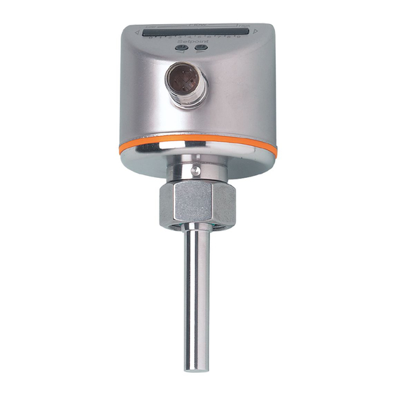
- Page 1 Operating instructions Flow monitors SI5010 ...
-
Page 2: Table Of Contents
Contents Preliminary note ��������������������������������������������������������������������������������������3 1�1 Symbols used ������������������������������������������������������������������������������������������������3 2 Safety instructions �����������������������������������������������������������������������������������������������3 3 Functions and features ����������������������������������������������������������������������������������������4 3�1 Application area ��������������������������������������������������������������������������������������������4 3�2 Operating principle flow monitoring ���������������������������������������������������������������4 3�3 Communication (IO-Link) �������������������������������������������������������������������������������4 4 Installation������������������������������������������������������������������������������������������������������������5 4�1 Installation location ����������������������������������������������������������������������������������������5 4�2 Sources of interference in the pipe system ���������������������������������������������������6 4�3 Mounting operation ����������������������������������������������������������������������������������������6 5 Electrical connection ��������������������������������������������������������������������������������������������7 6 Operating and display elements ��������������������������������������������������������������������������7... -
Page 3: Preliminary Note
1 Preliminary note 1.1 Symbols used ► Instruction > Reaction, result […] Designation of buttons, switches or indications → Cross-reference Important note Non-compliance can result in malfunctions or interference� 2 Safety instructions • Please read the product description prior to set-up of the unit� Ensure that the product is suitable for your application without any restrictions�... -
Page 4: Functions And Features
• The unit is laid out for bidirectional communication� So, the following options are possible: - Remote evaluation (transmission of the process data)� - Remote parameter setting (adjustment / output function)� Device-specific parameter lists for IO-Link parameter setting are available at: www�ifm�com → Select your country → Data sheet direct:... -
Page 5: Installation
• Adapters have to be ordered separately as accessories� A correct fit of the unit and ingress resistance of the connection are only en- sured using ifm adapters� • For small flow rates ifm adapter blocks are available� 4.1 Installation location General •... -
Page 6: 4�2 Sources Of Interference In The Pipe System
4.2 Sources of interference in the pipe system Components integrated in the pipes, bends, valves, reductions, etc� lead to turbu- lence of the medium� This affects the function of the unit� Recommendation: Adhere to the distances between sensor and sources of inter- ference: 5...10 x D 3...5 x D Flow High... -
Page 7: Electrical Connection
5 Electrical connection The unit must be connected by a qualified electrician� The national and international regulations for the installation of electrical equipment must be adhered to� Voltage supply to EN 50178, SELV, PELV� ► Disconnect power� ► Connect the unit as follows: Teach OUT1/Data •... -
Page 8: Set-Up And Settings For Water
7 Set-up and settings for water (For media other than water → 8�1: Low flow adjustment)� ► Switch on the supply voltage� > All LEDs light and go out again step by step� During this time the output is closed (if configured as normally open)� The unit is in the operating mode� ►... -
Page 9: 7�2 High Flow Adjustment (Optional)
7.2 High flow adjustment (optional) The unit determines the existing flow as normal flow and adapts the display repre- sentation (all LEDs except the switch point LED light green)� ► Let the normal flow circulate in the installation� ► Press the pushbutton and keep it pressed� >... -
Page 10: 8�3 Restore The Factory Setting (Reset)
8.3 Restore the factory setting (reset) ► Press the pushbutton for at least 15 s� > LED 9 lights, after approx� 5 s it flashes� > After approx� 15 s LEDs 0���9 flash orange� ► Release the pushbutton� All settings are reset to the factory setting: - operating area: 5 ���100 cm/s for water - switch point: LED 7 - output function: NO... -
Page 11: Operation
10 Operation After every power on all LEDs light and go out again step by step (during this time the output is closed if configured as normally open)� The unit is then ready for operation� In case of power failure or interruption all settings remain� Operating indicators ... -
Page 12: Scale Drawing
12 Scale drawing 1: LED bar display 2: set button 3: tightening torque 25 Nm 13 Technical data Application area ����������������������������������������������������������������������������������������Liquids and gases Operating voltage [V] ����������������������������������������������������������������������������������������19 ��� 36 DC Current rating [mA] ����������������������������������������������������������������������������������������������������������250 Short-circuit protection, pulsed; reverse polarity / overload protection Voltage drop [V] �������������������������������������������������������������������������������������������������������������<... - Page 13 EN 61000-4-4 Burst: ..................... 2 kV EN 61000-4-6 HF conducted: ..................10 V to EN50178, SELV, PELV; for water; 5...100 cm/s; 25°C (factory setting) for water; 5...100 cm/s; 10...70°C The sensor conforms to the standard EN 61000-6-2 More information at www.ifm.com...
Need help?
Do you have a question about the efector 300 SI5010 and is the answer not in the manual?
Questions and answers