Advertisement
Do you have a question about the ecofour 24 F and is the answer not in the manual?
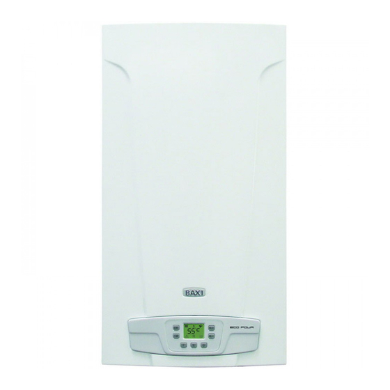
Котел постоянно греет воду, хотя краны закрыты


Need help?
Do you have a question about the ecofour 24 F and is the answer not in the manual?
Questions and answers
Котел постоянно греет воду, хотя краны закрыты