Table of Contents

Related Manuals for Haes MZAOV-1001


Summary of Contents for Haes MZAOV-1001
- Page 1 MULTIZONE AUTOMATICALLY OPENING VENT (MZAOV) CONTROL PANEL INSTALLATION, COMMISSIONING & OPERATING MANUAL This manual covers installation, programming commissioning of the Multizone Automatically Opening Vent Control Panel...
-
Page 2: Introduction
European Standard EN54-4: 1998 Power supply equipment for fire detection and fire alarm systems for buildings. Haes Technologies Ltd declare that the products identified above conform to the essential requirements specified in the Construction Products Regulation CPR305/2011/EU. In addition, the product complies with the following:... - Page 3 Multizone AOV User Manual INTRODUCTION List of optional functions with requirements: EN54-4: 1997 +A2 Power supply equipment for fire detection and fire alarm systems for buildings. Non-standard Provided Options: Charge during alarm Earth fault monitoring UPS Mode Changeable password for Level 2 Adjustable Date &...
-
Page 4: Safety
Multizone AOV User Manual SAFETY SAFETY IMPORTANT NOTICE PLEASE READ THIS MANUAL CAREFULLY BEFORE HANDLING THE EQUIPMENT AND OBSERVE ALL ADVICE GIVEN WITHIN IT. THIS PARTICULARLY APPLIES TO THE PRECAUTIONS NECESSARY TO AVOID ELECTRO-STATIC DISCHARGE Important Safety Notes The panel is safe to operate provided it has been installed in compliance with the manufacturer’s instructions and used in accordance with this manual. -
Page 5: Cautions
Multizone AOV User Manual SAFETY Cautions Equipment Guarantee This product has been manufactured in conformance with the requirements of all applicable EU Council Directives and is not guaranteed unless the complete system is installed and commissioned in accordance with the laid down national standards by an approved and competent person or organisation. -
Page 6: Table Of Contents
Technical Specification ....................20 General Specification ....................20 Power Supply Specification – PSM3 - 24 (MZAOV-1001 (3 Amp)) ......21 Power Supply Specification – PSM5 - 27 (MZAOV-1002 (5 Amp)) ......22 Power Supply Specification – PSM10-27 (MZAOV-1003 (10 Amp)) ......23 Electrical Specification - Inputs &... - Page 7 Multizone AOV User Manual TABLE OF CONTENTS Cable Lengths ......................28 Mains Provision ......................28 Detector Circuit Conventional System Schematic ............29 Detector Circuit Twin Wire System Schematic ............30 Twin Wire Mode ......................31 INSTALLATION ........................32 Safety ..........................32 ESD Precaution ......................
- Page 8 Multizone AOV User Manual TABLE OF CONTENTS Fire Alarm Condition ..................... 45 Fault Condition ......................45 Functionality during a system fault................45 CONFIGURING THE SYSTEM ................... 47 Accessing the Menu Structure ..................47 User Menu ........................49 User Menu: DISABLE ....................50 Disable Menu: REMOVE ALL Disablement ...............
- Page 9 Multizone AOV User Manual TABLE OF CONTENTS Report EVENTS Menu: ALARM ................80 Report EVENTS Menu: FAULT ................. 81 Report EVENTS Menu: DISABLE................82 Report EVENTS Menu: TEST ................... 83 Report EVENTS Menu: OTHER ................84 Report Menu: STATUS ....................85 Report STATUS Menu: AOV ..................
-
Page 10: Product Overview
Quality, reliability, ease of use and feature rich are attributes that are consistent across the entire range of Haes fire alarm control panels. The panels are available with three output options, 3 Amp, 5 Amp and 10 Amp for controlling medium to large loads. - Page 11 Multizone AOV User Manual PRODUCT OVERVIEW Additional control input/output cards are available, allowing for the use of PIR sensors, to prevent vents from closing when a trap hazard (i.e. arm or hand) exists, and rain sensors for inclement weather. The panels have a sheet steel enclosure, suitable for wall mounting, with a hinged and lockable front access door.
-
Page 12: Multi-Aov Cabinet
Multizone AOV User Manual PRODUCT OVERVIEW Multi-AOV Cabinet Approved Document Ref: UI-MAOV-01 Issue 1.0... -
Page 13: Circuit Boards
Multizone AOV User Manual PRODUCT OVERVIEW Circuit Boards PSU AOV Card – PCB-3037-212 Approved Document Ref: UI-MAOV-01 Issue 1.0... -
Page 14: Multi Aov Card (2-Way) - Pcb-3038-212
Multizone AOV User Manual PRODUCT OVERVIEW MULTI AOV Card (2-Way) – PCB-3038-212 Approved Document Ref: UI-MAOV-01 Issue 1.0... -
Page 15: Pir/Bms (Plug-In) Card (2-Way) - Pir-0-10-3041-212 (Optional)
Multizone AOV User Manual PRODUCT OVERVIEW PIR/BMS (Plug-in) Card (2-Way) – PIR-0-10-3041-212 (Optional) Approved Document Ref: UI-MAOV-01 Issue 1.0... -
Page 16: Circuit Description/Function
Multizone AOV User Manual PRODUCT OVERVIEW Circuit Description/Function PSU AOV Card – PCB-3037-212 (TPCA027) POWER IN A/POWER IN B (+ -) Two monitored 28VDC inputs from power supply module. Diode protected for reversal and independent short circuit. Maximum input current, 10 Amps. Input voltage 22 to 32VDC. Configurable for either one, or both, of the inputs to be used. -
Page 17: Multi Aov Card (2-Way) - Pcb-3038-212 (Tpca028)
Multizone AOV User Manual PRODUCT OVERVIEW SNDR 1 (+ -)/SNDR 2 (+ -) Two 24VDC programmable and monitored sounder outputs, configurable as FARE and FWRE (Fire and Fault routing). They can be programmed to turn OFF or ON in Continuously mode or in Pulsing mode (1s ON and 1s OFF). - Page 18 Multizone AOV User Manual PRODUCT OVERVIEW ACT 1/ACT 2 (+ -) Dual polarity reversal vent drive actuator outputs - 28VDC, max 8A, protected by a current trip circuit. Not normally powered. Operated by the inputs from either the main fireman switch, or the local vent control switches;...
-
Page 19: Pir/Bms Plug-In Card (2-Way) - Pir-0-10-3041-212 (Tpca029) (Optional)
Multizone AOV User Manual PRODUCT OVERVIEW OUTPUT 1/OUTPUT 2 (NO C) Reports when local vent zone is in alarm condition. PIR/BMS Plug-in Card (2-Way) – PIR-0-10-3041-212 (TPCA029) (Optional) One PIR card can be fitted to each of the Multi-AOV cards mounted in the panel. This means up to eight PIRs can be fitted in the system. - Page 20 Multizone AOV User Manual PRODUCT OVERVIEW RAIN (+ -) Signal input from wind/rain sensors. Typically, a wind/rain sensor will have a closing contact alarm signal and may require a 24V supply. The input requires a 2K7Ω impedance to trigger, with a 6K8Ω 5%0.25W EOL resistor. Monitoring current limit is 14mA, unfused. Up to 4 wind/rain sensors can be installed in the system;...
-
Page 21: Technical Specification
Multizone AOV User Manual PRODUCT OVERVIEW Technical Specification General Specification Enclosure Steel IP30. Epoxy powder coated Interpon Radon, silver grey Temperature range: -5°C to +40°C Maximum Relative Humidity: 1 – 4 (3A/5A) or 1 – 8 (10A) Number of conventional/twin wire detection circuits Conventional/twin wire detector Apollo: S65, Orbis. -
Page 22: Power Supply Specification - Psm3 - 24 (Mzaov-1001 (3 Amp))
Multizone AOV User Manual PRODUCT OVERVIEW Power Supply Specification – PSM3 - 24 (MZAOV-1001 (3 Amp)) Mains supply 230VAC +10% / -15% 50Hz max current 1.2 Amp Mains supply fuse 3.15 Amp (F3.15A 250V) Not accessible for servicing. Internal to switched mode power unit... -
Page 23: Power Supply Specification - Psm5 - 27 (Mzaov-1002 (5 Amp))
Multizone AOV User Manual PRODUCT OVERVIEW Power Supply Specification – PSM5 - 27 (MZAOV-1002 (5 Amp)) Mains supply 230VAC +10% / -15% 50Hz max current 1.2 Amp Mains supply fuse 3.15 Amp (F3.15A 250V) Not accessible for servicing. Internal to switched mode power unit Power supply rating 5 Amps total including battery Maximum load shared = 5 Amp... -
Page 24: Power Supply Specification - Psm10-27 (Mzaov-1003 (10 Amp))
Multizone AOV User Manual PRODUCT OVERVIEW Power Supply Specification – PSM10-27 (MZAOV-1003 (10 Amp)) Mains supply 230VAC +10% / -15% 50Hz max current 1.5 Amp Mains supply fuse 6.3 Amp (F6.3A 250V) Not accessible for servicing. Internal to switched mode power unit Power supply rating 10 Amps total including battery Maximum load shared = 10 Amp... -
Page 25: Electrical Specification - Inputs & Outputs
Multizone AOV User Manual PRODUCT OVERVIEW Electrical Specification - Inputs & Outputs PCB-3037-212 (TPCA027) PSU AOV Card POWER IN A/POWER IN 28VDC supply input. Diode protected Max input current; 5 amps (5A card) B - + for reversal and independent short or 10 amps (10A card). -
Page 26: Electrical Specification - Inputs & Outputs
Multizone AOV User Manual PRODUCT OVERVIEW Electrical Specification - Inputs & Outputs PCB-3038-212 (TPCA028) MULTI AOV Card ZONE 1/ZONE 2 + - Fire alarm zone circuit. Monitoring current limit is 50mA, fused Conventionally wired detection circuit at 500mA. Typical max load 22 or Twin wire combined devices, at 18mA each, in each zone detection/sounder circuit, monitored... -
Page 27: Design Considerations
Multizone AOV User Manual DESIGN CONSIDERATIONS DESIGN CONSIDERATIONS System Design and Planning Note: This guide is intended as an aid to designers and installers of fire detection systems. It is NOT to be used as a substitute to BS5839 which should be read in full. What is a detection zone? In order to direct those responding to a fire alarm signal, particularly the fire service, to the area of a fire, all buildings, other than very small buildings, need to be divided into detection... -
Page 28: Sounders
Multizone AOV User Manual DESIGN CONSIDERATIONS Sounders Sounder device cabling should be arranged so that in the event of a fault, at least one sounder will remain operational during a fire condition. The minimum sound level should be 65dB(A) or 5dB(A) above a background noise which is louder than 60dB(A) (if lasting more than 30 seconds) and at a frequency of between 500Hz and 1000Hz. -
Page 29: Cable Lengths
Multizone AOV User Manual DESIGN CONSIDERATIONS Cable Lengths The maximum recommended cable length for a zone or sounder circuit is 1Km. This, however, is highly dependent on the number and type of devices connected. If in doubt, cable load and resistance calculations should be undertaken to ensure devices are working within specified limits. -
Page 30: Detector Circuit Conventional System Schematic
Multizone AOV User Manual DESIGN CONSIDERATIONS Detector Circuit Conventional System Schematic Approved Document Ref: UI-MAOV-01 Issue 1.0... -
Page 31: Detector Circuit Twin Wire System Schematic
Multizone AOV User Manual DESIGN CONSIDERATIONS Detector Circuit Twin Wire System Schematic Approved Document Ref: UI-MAOV-01 Issue 1.0... -
Page 32: Twin Wire Mode
Multizone AOV User Manual DESIGN CONSIDERATIONS Twin Wire Mode Twin Wire, often referred to as sav wire, enables sounders and beacons to be connected to the same circuit as the detectors and call points. In Twin Wire configuration, the detector circuit reverses polarity, in alarm condition, to power the sounders and beacons. -
Page 33: Installation
Further copies of this User Instruction Manual are available from the website www.https://haes-tech.com. It is assumed that the system, of which this control panel is a part, has been designed by a competent fire alarm system designer in accordance with BS 7346 Part 8, BS 5839 Part 1 and with regard to BS EN 54 parts 2 and 4 in the case of control equipment and power supplies. -
Page 34: Installing The System
Multizone AOV User Manual INSTALLATION Installing the System General Take care to avoid mounting the cabinet near high voltage cables, or areas likely to induce electrical interference. Earth links should be maintained on all system cables and grounded in the control panel. Cabling for the detection and sounder circuits is classed as extra low voltage and must be segregated away from mains voltage. -
Page 35: Mains Connections
Multizone AOV User Manual INSTALLATION Mains Connections Note: All connections must be carried out in accordance with local requirements and regulations. Do not connect the mains supply to the panel until you are fully conversant with the layout and features of the equipment. A rating plate is attached to the power supply module, describing the nature of the supply permitted. -
Page 36: Battery Charging Voltage Checks
Multizone AOV User Manual INSTALLATION Note: In the event of mains power failure, the battery charger circuit will protect the batteries from full discharge by disconnecting them when they reach below 19v. When the mains supply is restored the batteries will be automatically reconnected. Note: If mains power is connected before the batteries, the panel will show a Power Supply fault for up to 1 minute until the monitoring cycle has finished polling. -
Page 37: Battery Charging Voltage Calibration
Multizone AOV User Manual INSTALLATION Battery Charging Voltage Calibration Should the battery charging voltage require calibrating (i.e. following replacement of the main board), proceed as follows: • Turn Activate Controls key clockwise to On • Use the keypad to enter Authorised User (Access level 2) code 1111: o Press ✓... -
Page 38: Sounders/Output Circuits
Multizone AOV User Manual INSTALLATION Sounders/Output Circuits Two (24VDC) programmable and monitored sounder output circuits are provided • They can be programmed to turn OFF or ON in Continuously mode or in Pulsing mode (1s ON and 1s OFF). • The sounders can be configured to be non-silencing or silencing. -
Page 39: Inputs - Class Change And Pulse
Multizone AOV User Manual INSTALLATION Inputs - Class Change and Pulse Class Change Switch (–ve) inputs which cause the common sounder and loop sounders outputs to operate. Pulse Switch (–ve) inputs which cause the common sounder and loop sounders outputs to pulse. P-BUS RS-485 local peripheral bus (P-BUS) circuit is for control of Remote Status Units (RSU), it is not intended for networking. -
Page 40: Operating Instructions
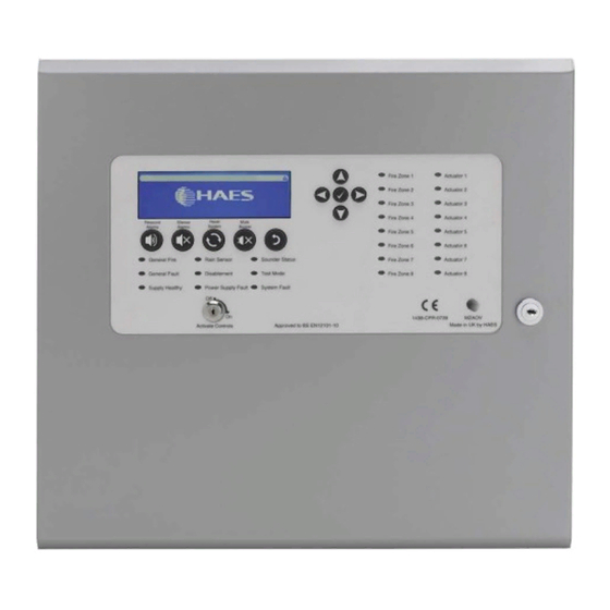
Multizone AOV User Manual OPERATING INSTRUCTIONS OPERATING INSTRUCTIONS Panel Control and Indicators Control Panel The control panel contains: • LCD display screen • 5-button control keypad • Up/down/left/right arrow keys and enter (✓) key curser control keypad • Panel status LED indicators •... -
Page 41: Keypads
Multizone AOV User Manual OPERATING INSTRUCTIONS Keypads Use to resound the alarms after they have been silenced. Can also be used to invoke full evacuation. Resound Alarms Use to silence the sounders during an alarm condition. Silence Alarms Resets the panel back to standby mode. Reset System Mutes the panels internal fire and fault buzzer. -
Page 42: Status Led Indicators
Multizone AOV User Manual OPERATING INSTRUCTIONS Status LED Indicators LED Name LED ON LED Pulsing Indicates panel is in alarm Indicates panel is in the General Alarm unsilenced alarm condition. condition that has been silenced. Indicates rain/wind sensor Indicates a fault in the Rain Status has been disabled. -
Page 43: User Controls
Multizone AOV User Manual OPERATING INSTRUCTIONS User Controls Four levels of control, with programmable code entry, are available on the panel: • General User (Access level 1) • Authorised User (Access level 2) • Engineer (Access level 3) (CONFIG Mode) •... -
Page 44: Available Functions
Multizone AOV User Manual OPERATING INSTRUCTIONS Once the four-digit code is entered, or the Activate Controls key is used, the LCD unit will display the Main Menu. Use the Scroll Control keypad up/down and left/right arrows, and the enter ✓ key to navigate the Access level 2 menu. Note: If the Activate Controls key is in the On position, the keypad will remain active. -
Page 45: Engineer Controls
Multizone AOV User Manual OPERATING INSTRUCTIONS Engineer Controls The Engineer (Access level 3) controls can be accessed by: • From the Authorised User (Access level 2) MAIN MENU, use Left/Right arrow keys to move cursor to CONFIG menu icon • Press ✓... -
Page 46: Panel Alarm Conditions
Multizone AOV User Manual OPERATING INSTRUCTIONS Panel Alarm Conditions Fire Alarm Condition The display shows location/origin of the fire alarm and the total number of vent zones in a fire alarm condition. If two or more vent zones enter the fire alarm condition, the display also shows the location of the last zone to enter a fire alarm condition. - Page 47 Multizone AOV User Manual OPERATING INSTRUCTIONS o Power Supply Fault LED pulsing o Fault relay activated o Mains or battery power will still operate the panel. Batteries will not be charging o Indications will remain until the fault is rectified and the panel is reset o Remote status units will cease to function.
-
Page 48: Configuring The System
Multizone AOV User Manual CONFIGURING THE SYSTEM CONFIGURING THE SYSTEM When the system is installed and is ready to be commissioned, configure as follows: • Use the CONFIG PANEL menu LEARN option, to enable the panel to automatically learn what internal cards, external devices (detectors, sounders, etc.), and Peripheral BUS (P-BUS) Remote Control Call Points are connected in the system. - Page 49 Multizone AOV User Manual CONFIGURING THE SYSTEM To access the menu structure: • Turn Activate Controls key switch clockwise to On • use the keypad to enter Authorised User (Access level 2) code 1111: • Press ✓ key to select Access level 2. The digital display will show the following message: Enter Level 2 Access Code o Use Up/Down arrow keys to increase/decrease the number value...
-
Page 50: User Menu
Multizone AOV User Manual CONFIGURING THE SYSTEM User Menu Accessible from the Main Menu (Access level 2); the User Menu, and its subsequent sub- menus, are used to set-up the panel ready for configuration. The sub-menus available are: • DISABLE o DISABLE Menu ▪... -
Page 51: User Menu: Disable
Multizone AOV User Manual CONFIGURING THE SYSTEM User Menu: DISABLE To enable/disable inputs, outputs, devices, zones and circuits, access the Disable Menu and its sub-menus: • On the Main Menu, use Left/Right arrow keys to move cursor box to User menu icon •... -
Page 52: Disable Menu: General
Multizone AOV User Manual CONFIGURING THE SYSTEM • When finished, press return key to return to DISABLE menu. • Next, press return key to return to the User menu. DISABLE Menu: GENERAL To enable or disable panel sounders, relays, outputs and switch inputs on the PSU card: •... -
Page 53: Disable Menu: Circuit
Multizone AOV User Manual CONFIGURING THE SYSTEM DISABLE Menu: CIRCUIT To enable or disable elements (zone, inputs, vents) of each detection circuit (depending on the AOV cards fitted): • On the Main Menu, use Left/Right arrow keys to move cursor box to User menu •... -
Page 54: Test Mode: On/Off
Multizone AOV User Manual CONFIGURING THE SYSTEM TEST MODE: ON/OFF This is the main activation control for TEST MODE along with sounder options, any Zones that have been set for TEST MODE will be disabled (i.e. operate normally) unless INCLUDE ALL ZONES or EXCLUDE ALL ZONES function has been set in TEST MODE: SETTINGS. -
Page 55: User Menu: Time & Date
Multizone AOV User Manual CONFIGURING THE SYSTEM • Under TEST SETTINGS sub-menu, the following options will be displayed: ZONES – use the Up/Down arrow keys to highlight the ZONES option and press ✓ key to select it. The following sub-menu will be displayed: TEST SETTINGS <ZONE 1 –... -
Page 56: User Time & Date Menu: Set Dst
Multizone AOV User Manual CONFIGURING THE SYSTEM User Time & Date Menu: Set DST To set the start and end of local Daylight Savings Time on the system: • On the Main Menu, use Left/Right arrow keys to move cursor box to User menu •... -
Page 57: User Menu: Lamp Test
Multizone AOV User Manual CONFIGURING THE SYSTEM User Menu: Lamp Test To operate the Lamp Test menu, to test the panel LCD display and warning LEDs: • On the Main Menu, use Left/Right arrow keys to move cursor box to User menu •... -
Page 58: User Menu: Contrast
Multizone AOV User Manual CONFIGURING THE SYSTEM User Menu: Contrast To set the LCD screen contrast and backlight, operate the Contrast menu: • On the Main Menu, use Left/Right arrow keys to move cursor box to User menu • Press ✓ key to select the User menu. •... -
Page 59: User Menu
Multizone AOV User Manual CONFIGURING THE SYSTEM User Menu Approved Document Ref: UI-MAOV-01 Issue 1.0... - Page 60 Multizone AOV User Manual CONFIGURING THE SYSTEM Approved Document Ref: UI-MAOV-01 Issue 1.0...
- Page 61 Multizone AOV User Manual CONFIGURING THE SYSTEM Approved Document Ref: UI-MAOV-01 Issue 1.0...
-
Page 62: Config Menu
Multizone AOV User Manual CONFIGURING THE SYSTEM CONFIG Menu Accessible from the Main Menu (Access level 2); the CONFIG Menu (Access level 3), and its subsequent sub-menus, are used to configure the panel and its attached devices. The sub- menus available are: •... -
Page 63: Config Menu: Panel
Multizone AOV User Manual CONFIGURING THE SYSTEM o When all 4 digits have been set to the code 3333 press ✓ key once again. The Access level 3 menu will become available for operation. Note: Access level 3 Menu will deactivate after 30 sec if not used. CONFIG Menu: PANEL To configure the Panel controls and outputs: CONFIG PANEL Menu: LEARN... -
Page 64: Config Panel Menu: Options
Multizone AOV User Manual CONFIGURING THE SYSTEM o P-BUS: The LEARN PANEL sub-menu will display a list containing all 32 of the possible RSUs that could be connected, using the P-BUS, and show if they are connected or not - indicated by PRESENT or NOT PRESENT: LEARN PANEL -P-BUS- 1: 1st RSU: PRESENT/NOT PRESENT... -
Page 65: Config Panel Menu: Default
Multizone AOV User Manual CONFIGURING THE SYSTEM Note: If SOUNDER TWO FWRE (option 3) is set to YES, faults on the SOUNDER TWO circuit will NOT be indicated (all other fault indications are unaffected). This feature does not conform with BS EN 54-2, clause 8.2.4 g) and clause 8.9. Note: With option 4 (CLOSE VENT ON POWER UP) set to YES;... -
Page 66: Config Panel Menu: Password
Multizone AOV User Manual CONFIGURING THE SYSTEM CONFIG PANEL Menu: Password To set the 4-digit access codes, access the Password menu: • Highlight PANEL option and then press ✓ key in order to gain access to it. • Highlight the Password option under the CONFIG PANEL menu and press ✓ key again. -
Page 67: Config Menu: Devices
Multizone AOV User Manual CONFIGURING THE SYSTEM Note: Option 1 refers to Normal/Twin Wire detector circuit (x1 per Area) – ZONE 1/ZONE 2 on AOV Card. Note: Option 2 is used for any additional inputs, not otherwise covered by Options 1 – 7, connected to AOV Card –... - Page 68 Multizone AOV User Manual CONFIGURING THE SYSTEM 4: INPUT CONTROL VENT 01 – 08 CONFIG CONTROL 1: INPUT ONE: OPEN VENT/CLOSE VENT/DISABLED 2: INPUT TWO: OPEN VENT/CLOSE VENT/DISABLED 8: INPUT EIGHT: OPEN VENT/CLOSE VENT/DISABLED 5: MANUAL CONTROL VENT 01 – 08 CONFIG CONTROL 1: MANUAL ONE: ENABLED/DISABLED 2: MANUAL TWO: ENABLED/DISABLED...
-
Page 69: Config Devices Menu: Zones
Multizone AOV User Manual CONFIGURING THE SYSTEM • For option 6: THERMOSTAT OPENING and option 7: THERMOSTAT CLOSING; press ✓ key to access change control. Use Up/Down arrow keys to toggle through thermostat position in 10% increments. Press ✓ key to lock change. •... -
Page 70: Config Devices Menu: Sounders
Multizone AOV User Manual CONFIGURING THE SYSTEM CONFIG DEVICES Menu: SOUNDERS To configure the various sounder outputs for the system, access the SOUNDERS menu: • On the CONFIG Menu, highlight DEVICES sub-menu and then press ✓ key in order to gain access to it. •... -
Page 71: Config Devices Menu: Relay
Multizone AOV User Manual CONFIGURING THE SYSTEM CONFIG DEVICES Menu: Relay To access the Relay menu: • On the CONFIG Menu, highlight DEVICES icon and then press ✓ key in order to gain access to CONFIG DEVICES menu. • Highlight the Relay option under the CONFIG DEVICES sub-menu, and press ✓ key again. -
Page 72: Config Menu: P-Bus
Multizone AOV User Manual CONFIGURING THE SYSTEM • Press the return key once to return to CONFIG Menu. A short acknowledgement sound will be present. • Note: The configuration of Power Supply Unit Settings function allows compliance with BS EN 54-2:1997 + A1:2006. •... -
Page 73: Config Menu
Multizone AOV User Manual CONFIGURING THE SYSTEM CONFIG Menu Approved Document Ref: UI-MAOV-01 Issue 1.0... - Page 74 Multizone AOV User Manual CONFIGURING THE SYSTEM Approved Document Ref: UI-MAOV-01 Issue 1.0...
- Page 75 Multizone AOV User Manual CONFIGURING THE SYSTEM Approved Document Ref: UI-MAOV-01 Issue 1.0...
- Page 76 Multizone AOV User Manual CONFIGURING THE SYSTEM Approved Document Ref: UI-MAOV-01 Issue 1.0...
- Page 77 Multizone AOV User Manual CONFIGURING THE SYSTEM Approved Document Ref: UI-MAOV-01 Issue 1.0...
- Page 78 Multizone AOV User Manual CONFIGURING THE SYSTEM Approved Document Ref: UI-MAOV-01 Issue 1.0...
- Page 79 Multizone AOV User Manual CONFIGURING THE SYSTEM Approved Document Ref: UI-MAOV-01 Issue 1.0...
-
Page 80: Report Menu
Multizone AOV User Manual CONFIGURING THE SYSTEM Report Menu From the Report menu, on the Main Menu, the following sub-menus are available: • REPORT o EVENTS ▪ ALARM ▪ FAULT ▪ DISABLE ▪ TEST ▪ OTHER o STATUS ▪ ▪ PSU Card ▪... -
Page 81: Report Menu: Events
Multizone AOV User Manual CONFIGURING THE SYSTEM Report Menu: EVENTS From the Report Menu EVENTS sub-menu, report screens on the number and type of events (Alarm, Fault, Disablements, etc.) can be displayed: Report EVENTS Menu: ALARM To get ALARM events information: •... -
Page 82: Report Events Menu: Fault
Multizone AOV User Manual CONFIGURING THE SYSTEM Report EVENTS Menu: FAULT To get FAULT events information: • On the Main Menu, use Left/Right arrow keys to move cursor box to Report icon • Press ✓ key to select the Report menu. •... -
Page 83: Report Events Menu: Disable
Multizone AOV User Manual CONFIGURING THE SYSTEM Report EVENTS Menu: DISABLE To get DISABLE events information on system disablements: • On the Main Menu, use Left/Right arrow keys to move cursor box to Report menu • Press ✓ key to select the Report menu. •... -
Page 84: Report Events Menu: Test
Multizone AOV User Manual CONFIGURING THE SYSTEM Report EVENTS Menu: TEST To open a report screen for TEST events information: • On the Main Menu, use Left/Right arrow keys to move cursor box to Report menu • Press ✓ key to select the Report menu. •... -
Page 85: Report Events Menu: Other
Multizone AOV User Manual CONFIGURING THE SYSTEM Report EVENTS Menu: OTHER To obtain a report on OTHER events information (any events not covered under ALARM, FAULT, DISABLE or TEST – e.g. Non-Fire alarm events): • On the Main Menu, use Left/Right arrow keys to move cursor box to Report menu •... -
Page 86: Report Menu: Status
Multizone AOV User Manual CONFIGURING THE SYSTEM Report Menu: STATUS From the Report STATUS sub-menu, status information can be displayed for AOV Cards, PSU card and the batteries: Report STATUS Menu: AOV • To get status information on the system’s AOV Card(s), access the AOV Card STATUS menu: •... -
Page 87: Report Status Menu: Psu Card
Multizone AOV User Manual CONFIGURING THE SYSTEM Report STATUS Menu: PSU Card To get status information for the panel’s PSU card, access the PSU Card Status menu: • On the Main Menu, use Left/Right arrow keys to move cursor box to Report menu. •... -
Page 88: Report Menu: History
Multizone AOV User Manual CONFIGURING THE SYSTEM Report Menu: HISTORY To access EVENT HISTORY information: • On the Main Menu, use Left/Right arrow keys to move cursor box to Report menu icon. • Press ✓ key to select the Report menu. •... -
Page 89: Report Menu: Counter
Multizone AOV User Manual CONFIGURING THE SYSTEM Report Menu: COUNTER To get ALARM COUNT information: • On the Main Menu, use Left/Right arrow keys to move cursor box to Report menu. • Press ✓ key to select the Report menu. •... - Page 90 Multizone AOV User Manual CONFIGURING THE SYSTEM AREA 2: VER: n.n.nn AREA 3: VER: n.n.nn AREA 4: VER: n.n.nn Note – Where: n = displayed number dd = day MMM = Month yy = year Note: The number of AREA versions displayed depends on the AOV Cards fitted. •...
-
Page 91: Report Menu
Multizone AOV User Manual CONFIGURING THE SYSTEM Report Menu Approved Document Ref: UI-MAOV-01 Issue 1.0... - Page 92 Multizone AOV User Manual CONFIGURING THE SYSTEM Approved Document Ref: UI-MAOV-01 Issue 1.0...
-
Page 93: Eng Menu
Multizone AOV User Manual CONFIGURING THE SYSTEM ENG Menu From the ENG menu on the Main Menu, the following sub-menus are available • OUTPUTS ENG Menu: OUTPUTS To set the test output for the external devices connected to the system, access the ENG menu OUTPUTS sub-menu: •... -
Page 94: Eng Menu
Multizone AOV User Manual CONFIGURING THE SYSTEM ENG Menu Approved Document Ref: UI-MAOV-01 Issue 1.0... -
Page 95: Service & Maintenance
Multizone AOV User Manual SERVICE & MAINTENANCE SERVICE & MAINTENANCE Note: The following section is a summary of the requirements in BS5839 Part 1. For comprehensive information, a copy of BS5839 Part 1 can be purchased from the British Standards Institution via their web site at www.bsi-global.com. The Need for Maintenance Your Fire Alarm System is working 24 hours a day, 365 days a year. -
Page 96: Periodic Inspection And Servicing
Multizone AOV User Manual SERVICE & MAINTENANCE test should be carried out at approximately the same time each week. Instructions to the occupants should be that they report any instance of poor audibility of the fire alarm signal. A different manual call point should be used at the time of every weekly test so that all manual call points in the building are tested in rotation over a prolonged period. -
Page 97: Schedule Of Testing
Multizone AOV User Manual SCHEDULE OF TESTING SCHEDULE OF TESTING This section to be used to record ALL weekly tests of the fire alarm system Date & Device Tested & Initials of Comments (if any) Location Tester Time of Test Approved Document Ref: UI-MAOV-01 Issue 1.0... - Page 98 Multizone AOV User Manual SCHEDULE OF TESTING Date & Device Tested & Initials of Comments (if any) Location Tester Time of Test Approved Document Ref: UI-MAOV-01 Issue 1.0...
- Page 99 Multizone AOV User Manual SCHEDULE OF TESTING Date & Device Tested & Initials of Comments (if any) Location Tester Time of Test Approved Document Ref: UI-MAOV-01 Issue 1.0...
- Page 100 Multizone AOV User Manual SCHEDULE OF TESTING Date & Device Tested & Initials of Comments (if any) Location Tester Time of Test Approved Document Ref: UI-MAOV-01 Issue 1.0...
- Page 101 [Type here]...
Need help?
Do you have a question about the MZAOV-1001 and is the answer not in the manual?
Questions and answers