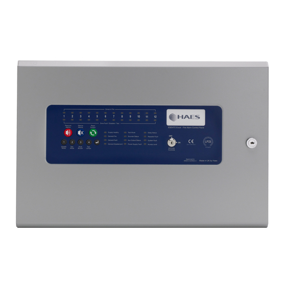
Summary of Contents for Haes AlarmSense PLUS
- Page 1 EN54 APPROVED 8-12 ZONE PULSE2 ALARMSENSE PLUS CONTROL PANEL 810a/06 Document EUFS-UI-ASP-02 Issue 1.0...
-
Page 2: Important Safety Notes
0832 Haes Systems Ltd, Columbia House, Packet Boat Lane, Cowley Peachey, Uxbridge, UB8 2JP Model Number CPR Number Haes AlarmSense PLUS 4-12 zone AlarmSense panel ASP-4/8/12 0832-CPR-F0574 European Standard EN54-2 : 1997 + A1 : 2006 Control and indicating equipment for fire detection and fire alarm systems for buildings. -
Page 3: Mains Connections
If the mains is connected before the batteries, the panel will show a Power Supply fault for up to 1 minute until the monitoring cylce has finished polling. This is normal. If the fault doesn’t clear after 1 minute, check connections. AlarmSense PLUS Quick Start Guide Document Ref: EUFS-UI-ASP-02 Issue 1.0... - Page 4 Switch 1 – OFF = Priority (default) ON = Non-priority Switch 2 – OFF = High volume (default) ® Please refer to the Apollo AlarmSense Installation Guide for device connection details AlarmSense PLUS Quick Start Guide Document Ref: EUFS-UI-ASP-02 Issue 1.0...
- Page 5 ‘Evacuate’, ‘Class Change’, ‘Alert’, ‘Delay’, ‘Non Priority’ and 4344, 4343 ‘Coincidence Alarm’ System Diagnostics Mode Tests system PCB config setup for fault diagnosis 3114 Repeater Programming Repeater panel setup & programming 4443 AlarmSense PLUS Quick Start Guide Document Ref: EUFS-UI-ASP-02 Issue 1.0...
-
Page 6: Panel Controls & Indications
After activation by code entry, controls will automatically deactivate again after 2 minutes and the panel will return to standby mode. The test lamps and mute buzzer functions are operational without the need to activate controls. AlarmSense PLUS Quick Start Guide Document Ref: EUFS-UI-ASP-02 Issue 1.0... -
Page 7: Disable Mode
With the controls active, pressing the Disable Mode button briefly will reveal which circuits are disabled (as opposed to in test mode). This is useful if using Disable Mode and Test Mode at the same time. AlarmSense PLUS Quick Start Guide Document Ref: EUFS-UI-ASP-02 Issue 1.0... -
Page 8: Test Mode
With the controls active, pressing the Test Mode button briefly will reveal which circuits are in test mode (as opposed to disabled). This is useful if using Disable Mode and Test Mode at the same time. AlarmSense PLUS Quick Start Guide Document Ref: EUFS-UI-ASP-02 Issue 1.0... -
Page 9: Fault Diagnosis
Zone 1 - 4 Fault/ Zone # disabled or Disabled/Test LED in test mode (steady) Power Supply Mains failure Battery failure or Voltage fault Main PCB Fault LED high impedance (pulsing) AlarmSense PLUS Quick Start Guide Document Ref: EUFS-UI-ASP-02 Issue 1.0... - Page 10 SCHEDULE OF TESTING This Section To Be Used To Record ALL Weekly Tests Of The Fire Alarm System DATE & DEVICE TESTED COMMENTS INITIALS & LOCATION (IF ANY) TIME OF TEST TESTER Excel-EN Quick Start Guide Approved Document Ref: UI-XLEN-03 Issue 1.0...
- Page 11 USER INSTRUCTIONS If an alarm condition is present YOU MUST FOLLOW YOUR NORMAL FIRE DRILL PROCEDURES. A responsible person should then:- Check the control panel to see which area or zone has caused the system to go into alarm. This will be indicated by a pulsing red LED on the front of the control panel.
- Page 12 EU Fire & Security Units 2-4 The Pavilions, Bridgefold Road, Rochdale OL11 5BY...


Need help?
Do you have a question about the AlarmSense PLUS and is the answer not in the manual?
Questions and answers