Table of Contents

Related Manuals for Haes Excel-32 Series


Summary of Contents for Haes Excel-32 Series
- Page 1 www.acornfiresecurity.com EN54 APPROVED 16 - 32 ZONE CONVENTIONAL CONTROL PANEL Installation, Commissioning & Operating Manual 810a/08 S o f t w a r e V e r s i o n 4 . 0 & A b o v e Approved Document UI-XL32-01 Issue 3.0 www.acornfiresecurity.com...
- Page 2 0832 Haes Systems Ltd, Columbia House, Packet Boat Lane, Cowley Peachey, Uxbridge, UB8 2JP Model Number CPR Number XL32, 16 - 32 zone conventional panel XL32-16/24/32 0832-CPR-F0837 European Standard EN54-2 : 1997 + A1 : 2006 Control and indicating equipment for fi re detection and fi re alarm systems for buildings.
-
Page 3: Table Of Contents
www.acornfiresecurity.com CONTENTS Page ABOUT THIS PANEL PRODUCT OVERVIEW CABINET DETAILS CIRCUIT BOARDS MAIN PCB TERMINALS TECHNICAL SPECIFICATION POWER SUPPLY MODULE DESIGN CONSIDERATIONS SYSTEM DESIGN & PLANNING GENERAL DETECTION CIRCUIT WIRIING SCHEMATIC GENERAL SOUNDER CIRCUIT WIRIING SCHEMATIC INSTALLATION SAFETY ESD PRECAUTIONS GENERAL MOUNTING THE CABINET MAINS CONNECTIONS... -
Page 4: About This Panel
Quality, reliability, ease of use and feature rich are attributes that are consistent across the entire range of Haes fi re alarm control panels. The Haes Excel-32 encompasses all of these attributes to provide the fi re Haes fi re alarm control panels. The Haes Excel-32 encompasses all of these attributes to provide the fi re alarm engineer’s panel of choice. -
Page 5: Cabinet Details
www.acornfiresecurity.com ABOUT THIS PANEL CABINET 107mm 130mm Fire Detection System 410mm 465mm 400mm 450mm 450mm XL32 Installation, Commissioning & Operating Manual Approved Document Ref: UI-XL32-01 Issue 3.0 www.acornfiresecurity.com... -
Page 6: Circuit Boards
www.acornfiresecurity.com ABOUT THIS PANEL CIRCUIT BOARDS Excel-32 panels comprise of two main circuit boards plus an optional comms board TPCA11 - Master PCB 28V 0V FIRE FAULT SNDR1 SNDR2 SNDR3 SNDR4 ZONE1 ZONE2 ZONE3 ZONE4 ZONE5 ZONE6 ZONE7 ZONE8 ZONE9 ZONE10 ZONE11 ZONE12 ZONE13 ZONE14 ZONE15 ZONE16 + - + - + - + -... -
Page 7: Main Pcb Terminals
www.acornfiresecurity.com ABOUT THIS PANEL MAIN PCB TERMINALS 28V 0V FIRE FAULT SNDR1 SNDR2 SNDR3 SNDR4 ZONE1 ZONE2 ZONE3 ZONE4 ZONE5 ZONE6 ZONE7 ZONE8 ZONE9 ZONE10 ZONE11 ZONE12 ZONE13 ZONE14 ZONE15 ZONE16 + - + - + - + - + - + - + - + - C NC NO C NC NO... -
Page 8: Technical Specification
www.acornfiresecurity.com ABOUT THIS PANEL TECHNICAL SPECIFICATION Electrical Specifi cation Inputs & Outputs - TPCA11-16/24/32 Main PCB Terminal capacity 0.5mm to 2.5mm solid or stranded wire. PSU TX/RX Power supply data control lines. RS232 data. PSU Input A +/-, B +/- 28vdc supply input. -
Page 9: Power Supply Module
www.acornfiresecurity.com ABOUT THIS PANEL POWER SUPPLY MODULE Power Supply Specifi cation Mains supply 230vac +10% / -15% 50Hz max current 1.9A Mains supply fuse 3.15 Amp (F3.15A 250V) Not accessible for servicing. Internal to switch mode power unit Internal power supply rating 5.0 Amps total including battery charging Maximum load shared between outputs = 5A... -
Page 10: Design Considerations
www.acornfiresecurity.com DESIGN CONSIDERATIONS This guide is intended as an aid to designers and installers of fi re SYSTEM DESIGN & PLANNING - A few handy tips detection systems. It is NOT to be used as a substitute to BS5839 which should be read in full. - Page 11 www.acornfiresecurity.com DESIGN CONSIDERATIONS Beacons • Visual alarms such as beacons, should always be mounted at a minimum height of 2.1m from fl oor level. General • Fire Alarm Control Panels should be installed at a location appropriate for staff and fi re fi ghters •...
-
Page 12: General Detection Circuit Wiriing Schematic
www.acornfiresecurity.com DESIGN CONSIDERATIONS GENERAL DETECTION CIRCUIT SCHEMATIC 4K7 OHM END OF LINE RESISTOR APOLLO S65 BASE 45681-201 MANUAL CALL POINT MCP1A-R-470 APOLLO S65 BASE 45681-201 APOLLO S65 BASE 45681-201 ZONE 1 XL32 Installation, Commissioning & Operating Manual Approved Document Ref: UI-XL32-01 Issue 3.0 www.acornfiresecurity.com... -
Page 13: General Sounder Circuit Wiriing Schematic
www.acornfiresecurity.com DESIGN CONSIDERATIONS GENERAL SOUNDER CIRCUIT SCHEMATIC 4K7 OHM END OF LINE RESISTOR MOTORISED BELL POLARISED MOTORISED BELL POLARISED ELECTRONIC SOUNDER POLARISED ELECTRONIC SOUNDER POLARISED SNDR1 XL32 Installation, Commissioning & Operating Manual Approved Document Ref: UI-XL32-01 Issue 3.0 www.acornfiresecurity.com... -
Page 14: Installation
www.acornfiresecurity.com INSTALLATION SAFETY Suppliers of articles for use at work are required under section 6 of the Health and Safety at Work Act 1974 Suppliers of articles for use at work are required under section 6 of the Health and Safety at Work Act 1974 to ensure as reasonably as is practical that the article will be safe and without risk to health when properly to ensure as reasonably as is practical that the article will be safe and without risk to health when properly used. -
Page 15: Esd Precautions
www.acornfiresecurity.com INSTALLATION ESD PRECAUTION Electronic components are vulnerable to damage by Electrostatic Discharges (ESD). An ESD wrist strap, Electronic components are vulnerable to damage by Electrostatic Discharges (ESD). An ESD wrist strap, suitably grounded, should be worn at all times when handling pcbs. These wrist straps are designed to suitably grounded, should be worn at all times when handling pcbs. -
Page 16: Mains Connections
www.acornfiresecurity.com INSTALLATION Typical panel layout Incoming mains wiring Low voltage detection and sounder circuit wiring 28V 0V FIRE FAULT SNDR1 SNDR2 SNDR3 SNDR4 ZONE1 ZONE2 ZONE3 ZONE4 ZONE5 ZONE6 ZONE7 ZONE8 ZONE9 ZONE10 ZONE11 ZONE12 ZONE13 ZONE14 ZONE15 ZONE16 C NC NO C NC NO + - + - + - + -... -
Page 17: Connecting The Batteries
www.acornfiresecurity.com INSTALLATION CONNECTING THE BATTERIES Batteries of even very small capacity are capable of delivering very high currents which can cause fi re or injury, therefore battery connections should be done with caution. The panel is supplied with battery leads already connected to the battery terminals on the main PCB. These leads are coloured red for +ve and black for -ve. -
Page 18: Setup & Programming
www.acornfiresecurity.com SETUP & PROGRAMMING NETWORK PANELS SETUP The system can support up to 8 networked control panels, 1 x Master and up to 7 x Slaves. Comms PCB To run a network, a Comms PCB (TPCA05) must be fi tted to each control panel. Any Excel-EN or Excel-32 panel from 2 to 32 zones with software version 4.0 and above may be used. - Page 19 www.acornfiresecurity.com SETUP & PROGRAMMING Programming The Master panel will need to be programmed for the number of network panels on the system. See panel wide programming settings, code 2-1-2-3, option 10, (Set Number of Network Slave Panels on System). Addressing Each panel needs to have a unique address.
-
Page 20: Zone Interface Function
www.acornfiresecurity.com SETUP & PROGRAMMING ZONE INTERFACE FUNCTION This setting confi gures the last zone on the panel, (i.e. zone 16 on a 16 zone, zone 24 on a 24 zone and zone 32 on a 32 zone), to be used for interconnection from other control panels. It is possible, in the Level 3 engineering programming, to setup any zone for this function, however, this is simply a shortcut method. -
Page 21: Level 3 Engineering Mode
www.acornfiresecurity.com SETUP & PROGRAMMING LEVEL 3 ENGINEERING OPTIONS A series of programmable engineering options are available. These programming modes are initiated by entering a four digit code using RESOUND SILENCE RESET buttons 1 - 4 on the keypad followed by the ENTER button. ENTER Disable Test... - Page 22 www.acornfiresecurity.com SETUP & PROGRAMMING PROGRAMMING OPTIONS INDEX Option/Setting Description Code(s) Page View History View the last 40 events 1111 Set Fault Buzzer Volume Set the fault buzzer volume to high or low 2224 Clear All Disablements Remove all disablements which have been set for any zone, 1121 sounder circuit, output or delay Initialise Factory Settings...
- Page 23 www.acornfiresecurity.com SETUP & PROGRAMMING View History The control panel stores a log of the last 40 events which have occurred. This is useful for identifying intermittent faults or activations. Enter the above code and press ENTER, the most recent event that has RESOUND SILENCE RESET...
- Page 24 www.acornfiresecurity.com SETUP & PROGRAMMING Set Fault Buzzer Volume There are two levels of volume for the internal fault buzzer, high and low. RESOUND SILENCE RESET Enter the above code and press the ENTER button to increase or decrease the fault buzzer tone from the previous level. ENTER Setting will change when ENTER button is pressed.
- Page 25 www.acornfiresecurity.com SETUP & PROGRAMMING Power Supply Settings (EN54!) Enter the above code and press the ENTER button. RESOUND SILENCE RESET There are 7 option settings for the integral power supply module which can be set up using the panel controls. ENTER 1.
- Page 26 www.acornfiresecurity.com SETUP & PROGRAMMING Panel Wide Settings RESOUND SILENCE RESET There are 9 general, panel wide, settings available. Enter the above code and press the ENTER button. The 9 programmable ENTER options are represented by fi re zone LEDs 1 - 11. Disable Test Mute...
- Page 27 www.acornfiresecurity.com SETUP & PROGRAMMING OPTION 2. Set Number of Repeater Panels on System If repeater panels are to be used, the quantity on the system, 1- 8, must be set up for monitoring purposes. An incorrect quantity will cause a repeater fault to be shown on the panel. With the zone 2 fi...
- Page 28 www.acornfiresecurity.com SETUP & PROGRAMMING OPTION 6. Change Network/Repeater Comms Monitoring Type (EN54!) The network & repeater panels are designed to be wired in a fault tolerant (fail safe) loop confi guration, from comms A to B and back to the main panel again (see drawing below). This enables network & repeater panels to still work if there is a break in the cables.
- Page 29 www.acornfiresecurity.com SETUP & PROGRAMMING OPTION 7 . Set Number of Output Cards Up to 4 output/relay cards may be added to each control panel to provide additional common or zonal outputs. The presence of the cards must be setup to enable operation. With the zone 7 fi...
- Page 30 www.acornfiresecurity.com SETUP & PROGRAMMING OPTION 9 . Inhibit Network Alarms & Faults For Panel This option prevents any other network panel’s alarms or faults from displaying or having any effect on the panel. The default setting is ON (panel displays all network alarms & faults and the outputs respond accordingly). If set to OFF, alarms &...
- Page 31 www.acornfiresecurity.com SETUP & PROGRAMMING OPTION 10 . Set Number of Network Slave Panels on System Cont’d.. Tip - You can use button 4 as a shortcut to add or remove all 7 addresses in one go. RESOUND SILENCE RESET ENTER Disable Test Mute...
- Page 32 www.acornfiresecurity.com SETUP & PROGRAMMING Zone Function Settings There are 8 functional settings available for each zone. These are as follows: Fire latching Normally a zone latches a fi re input signal. This setting allows the panel to clear automatically when a fi re signal is removed.
- Page 33 www.acornfiresecurity.com SETUP & PROGRAMMING Enter the code 3 1 2 1 and press the ENTER button. The zone 1 fi re LED will light. This indicates setting the above zone function attributes for zone 1. The amber, fault LEDs will show the current settings for that zone. RESOUND SILENCE RESET...
- Page 34 www.acornfiresecurity.com SETUP & PROGRAMMING Gate Valve Indication The gate valve open position (i.e ready to allow water to pass through the valve in the event of fi re) is the normal default valve position and can be indicated on the panel with the red fi re LED. If the gate valve is closed, the zone fault LED is illuminated.
- Page 35 www.acornfiresecurity.com SETUP & PROGRAMMING ZONE B - Set to Fire Pump Indication The second zone will confi rm that the pump has started to run due to demand for fi re extinuishing water: Pump idle; • i.e. 4K7 EOL resistor only. No indication at all (normal) Pump running;...
- Page 36 www.acornfiresecurity.com SETUP & PROGRAMMING DEPENDENCY MODES (FALSE ALARM MANAGEMENT) Dependency modes are features described in EN54-2 for the processing of confi rmation alarms. It is a requirement by some monitoring stations and local fi re authoities in order to reduce the possibility of false alarms.
- Page 37 www.acornfiresecurity.com SETUP & PROGRAMMING Dependency Mode Selection To change the dependency mode type for the panel, enter the above code and press ENTER (panel is set to type A by default). The amber, fault LED 1 will pulse and the current setting will be indicated by a steady amber, fault LED as per table below.
- Page 38 www.acornfiresecurity.com SETUP & PROGRAMMING Set Timings For Dependency Mode B There are two programmable timings for dependency mode B, the confi rmation time , and the auto reset time Enter the above code and press ENTER. The fi re LED 1 will light indicating changing the timing for the confi...
- Page 39 www.acornfiresecurity.com SETUP & PROGRAMMING EN54 Sounder Resound Options By default, after an initial fi re condition and the (blue) Silence Alarms button has been activated, any new fi re condition in a different zone will cause the alarms to resound. It is possible to change this on a zonal basis so that any new alarm in a different zone will not resound the alarms.
- Page 40 www.acornfiresecurity.com SETUP & PROGRAMMING Apply Delay to Outputs For Selected Zones The activation of sounder circuits and aux outputs can be delayed in response to selected zones. The actual delay time is set up in the panel wide programming options, 2-1-2-3. The setting of delays here applies to all sounder circuits, all aux outputs or all sounder circuits and all aux outputs.
- Page 41 www.acornfiresecurity.com SETUP & PROGRAMMING Input Function Settings The panel has four inputs, located on the main circuit board, Class Change (CC), Alert (PUL), Remote Reset (RS) and Remote Silence Alarms (SA). Switching a negative voltage into these inputs will cause the alarm sounders to operate, silence or the panel to reset.
- Page 42 www.acornfiresecurity.com SETUP & PROGRAMMING Output Programmability & Miscellaneous All of the relays & outputs on the control panel’s main circuit board (TPC-A01) have default functions, i.e. operate on fi re or fault. The function for each of these outputs, however, can be changed. The outputs can also be programmed to have different responses for selected zones.
- Page 43 www.acornfiresecurity.com SETUP & PROGRAMMING Relay & Output Responses to Selected Zones Each of the relays and switched -ve outputs on the main circuit board can be independently programmed to respond in one of three different ways for each zone. The options are ON, OFF or PULSING. Note:- (Before any programming can be applied to the outputs on the main circuit board, they must fi...
- Page 44 www.acornfiresecurity.com SETUP & PROGRAMMING Conventional Sounder Circuit Responses to Selected Zones Each of the conventional sounder circuits on the main circuit board can be independently programmed to respond in one of three different ways for each zone, ON, OFF or PULSING. Enter the above code and press the ENTER button.
- Page 45 www.acornfiresecurity.com SETUP & PROGRAMMING Conventional Sounder Circuit Functional Options Each of the sounder circuits on the main circuit board can be independently programmed with a custom response to; Silence Alarms (including, Silence button or input programmed for remote Silence Alarms), Evacuate (including, Resound button, input programmed for Evacuate or 220Ω...
- Page 46 www.acornfiresecurity.com SETUP & PROGRAMMING Relay & Output Functional Options Each of the relays and switched -ve outputs on the main circuit board can be independently programmed with a custom response to; Silence Alarms (including, Silence button or input programmed for remote Silence Alarms), Evacuate (including, Resound button, input programmed for Evacuate or 220Ω...
- Page 47 www.acornfiresecurity.com SETUP & PROGRAMMING Sounder Circuit Network Responses The four sounder circuits in the panel will, by default, activate continuously for any fi re condition from the entire network. This option enables the default to be changed for each of the local circuits. The response can be either; CONTINUOUS, PULSING or NONE when a fi...
- Page 48 www.acornfiresecurity.com SETUP & PROGRAMMING Output & Relay Network Responses The Fire relay and FR switched negative output in the panel will, by default, activate continuously for any fi re condition from the entire network. The Fault relay and other switched negative outputs will also activate continuously, by default, if they have been made programmable using programming option 4-1-4-2.
- Page 49 www.acornfiresecurity.com SETUP & PROGRAMMING Comms PCB Outputs Response to Selected Zones If a repeater Comms PCB (TPCA05) has been fi tted to the panel, there are 6, swtched -ve outputs on the PCB which can be programmed to respond to selected zones in the same way as the other outputs and sounder circuits.
- Page 50 www.acornfiresecurity.com SETUP & PROGRAMMING Comms PCB Output Functional Options If a repeater Comms PCB (TPCA05) has been fi tted to the panel, the 6, swtched -ve outputs on the PCB can also be independently programmed with a custom response to; Silence Alarms (including, Silence button or input programmed for remote Silence Alarms), Evacuate (including, Resound button, input programmed for Evacuate or 220Ω...
- Page 51 www.acornfiresecurity.com SETUP & PROGRAMMING System Diagnostics Mode System faults can occur if a PCB in the control panel or one of the repeater panels stops working. This may be due to a fault condition, loss of power, software lockup or memory checksum error. A system fault can also occur if the internal PCB confi...
- Page 52 www.acornfiresecurity.com SETUP & PROGRAMMING REPEATER PANEL SETUP & PROGRAMMING The panel can support up to 8, fully functional repeater panels on the network which can be either the 12 way repeater panels or Remote Display Units or a combination of both. N.B. The 12 way repeater panel will only display the fi...
- Page 53 www.acornfiresecurity.com SETUP & PROGRAMMING Wiring Fault Tolerant Loop Wiring The repeater panels are designed to be wired in a fault tolerant (fail safe) loop confi guration, from comms A to B and back to the main panel again (see diagram). This enables repeater panels to still work if there is a break in the cables.
-
Page 54: Operating
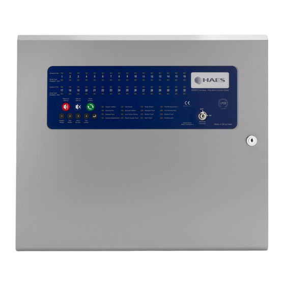
www.acornfiresecurity.com OPERATING PANEL CONTROLS & INDICATIONS Zonal Fire & Fault Indicator LEDs Zones in Fire Zone Fault Disabled / Test Zones in Fire Zone Fault Fire Detection System Disabled / Test RESOUND SILENCE RESET Test Mode Delay Status Fire Routing Active Supply Healthy Sounder Status Repeater Fault... - Page 55 www.acornfiresecurity.com OPERATING Status LED Indicators LED On LED Pulsing Zones in Fire 1 - 32 Indicates alarm condition in zone. Zone Fault/Disabled/Test Indicates zone circuit is disabled or in test Indicates a fault in the zone circuit. 1 - 32 mode.
-
Page 56: Disable Mode
www.acornfiresecurity.com OPERATING DISABLE MODE Disable Mode is used to disable or isolate individual zone circuits or all sounder circuits, all auxiliary outputs and any delays to outputs. To initialise Disable Mode fi rstly activate the controls by turning RESOUND SILENCE RESET the key switch or by entering the four digit code. -
Page 57: Test Mode
www.acornfiresecurity.com OPERATING TEST MODE Test Mode is used when testing the fi re alarm system. In test mode the devices in the zone(s) in test, detectors and call points etc, can be activated and the panel will automatically reset, enabling the system to be tested by one person. -
Page 58: Fault Diagnosis
www.acornfiresecurity.com OPERATING FAULT DIAGNOSIS If the panel has detected a fault on the system the General Fault LED will be illuminated and the internal fault buzzer will sound. Secondary LEDs will also be illuminated depending on the location of the fault. Pressing and holding the ENTER button will reveal more detailed information about the loction and type of fault. -
Page 59: Functionality During A System Fault
www.acornfiresecurity.com OPERATING FUNCTIONALITY DURING A SYSTEM FAULT A system fault is indicated when a processor controlling a function in the panel has a watchdog time out or processor failure. In the event of a system fault the particular board affected may not be functional. The following indications may be observed. -
Page 60: Service & Maintenance
www.acornfiresecurity.com SERVICE & MAINTENANCE The following section is a summary of the requirements in BS5839 Part 1 For comprehensive information a copy of BS5839 Part 1 can be purchased from the British Standards Institution via their web site at www.bsi-global.com. THE NEED FOR MAINTENANCE Your Fire Alarm System is working 24 hours a day, 365 days a year. - Page 61 www.acornfiresecurity.com SERVICE & MAINTENANCE WEEKLY TEST The call point test key should be inserted fi rmly and deliberately into the bottom of the manual call point. Once activated it may be necessary to wait up to four seconds before the alarms sound. Your manual call points may not be the same as the ones described above.
-
Page 62: Schedule Of Testing Log Book
www.acornfiresecurity.com SCHEDULE OF TESTING This Section To Be Used To Record ALL Weekly Tests Of The Fire Alarm System DDATE & DEVICE TESTED & COMMENTS INITIALS OF LOCATION (IF ANY) TESTER TIME OF TEST XL32 Installation, Commissioning & Operating Manual Approved Document Ref: UI-XL32-01 Issue 3.0 www.acornfiresecurity.com... - Page 63 www.acornfiresecurity.com SCHEDULE OF TESTING This Section To Be Used To Record ALL Weekly Tests Of The Fire Alarm System DDATE & DEVICE TESTED & COMMENTS INITIALS OF LOCATION (IF ANY) TESTER TIME OF TEST XL32 Installation, Commissioning & Operating Manual Approved Document Ref: UI-XL32-01 Issue 3.0 www.acornfiresecurity.com...
- Page 64 www.acornfiresecurity.com SCHEDULE OF TESTING This Section To Be Used To Record ALL Weekly Tests Of The Fire Alarm System DDATE & DEVICE TESTED & COMMENTS INITIALS OF LOCATION (IF ANY) TESTER TIME OF TEST XL32 Installation, Commissioning & Operating Manual Approved Document Ref: UI-XL32-01 Issue 3.0 www.acornfiresecurity.com...
- Page 65 www.acornfiresecurity.com SCHEDULE OF TESTING This Section To Be Used To Record ALL Weekly Tests Of The Fire Alarm System DDATE & DEVICE TESTED & COMMENTS INITIALS OF LOCATION (IF ANY) TESTER TIME OF TEST XL32 Installation, Commissioning & Operating Manual Approved Document Ref: UI-XL32-01 Issue 3.0 www.acornfiresecurity.com...
-
Page 66: False Alarms, Faults & Engineer Visit Log Book
www.acornfiresecurity.com FALSE ALARMS, FAULTS & ENGINEERS VISITS Fault/Reason For Action Taken Date Work Completed Engineer’s Details Call-Out XL32 Installation, Commissioning & Operating Manual Approved Document Ref: UI-XL32-01 Issue 3.0 www.acornfiresecurity.com... - Page 67 www.acornfiresecurity.com FALSE ALARMS, FAULTS & ENGINEERS VISITS Fault/Reason For Action Taken Date Work Completed Engineer’s Details Call-Out XL32 Installation, Commissioning & Operating Manual Approved Document Ref: UI-XL32-01 Issue 3.0 www.acornfiresecurity.com...
- Page 68 www.acornfiresecurity.com FALSE ALARMS, FAULTS & ENGINEERS VISITS Fault/Reason For Action Taken Date Work Completed Engineer’s Details Call-Out XL32 Installation, Commissioning & Operating Manual Approved Document Ref: UI-XL32-01 Issue 3.0 www.acornfiresecurity.com...
-
Page 69: User Instructions
www.acornfiresecurity.com USER INSTRUCTIONS If an alarm condition is present YOU MUST FOLLOW YOUR NORMAL FIRE DRILL PROCEDURES. A responsible person should then:- 1. 1. Check the control panel to see which area or zone has caused the system to go into alarm. This will Check the control panel to see which area or zone has caused the system to go into alarm. - Page 70 www.acornfiresecurity.com www.acornfiresecurity.com...
Need help?
Do you have a question about the Excel-32 Series and is the answer not in the manual?
Questions and answers