
Related Manuals for Haes SZAOV


Summary of Contents for Haes SZAOV
- Page 1 SZAOV CONTROL PANEL INSTALLATION, COMMISSIONING & OPERATING MANUAL This manual covers installation, programming commissioning of the Single Zone Automatically Opening Vent Control Panel (SZAOV)
-
Page 2: Introduction
Single Zone AOV User Manual INTRODUCTION INTRODUCTION 2797-CPR-747546 Haes Technologies Ltd, Unit 3, Horton Industrial Park, West Drayton, Uxbridge, UB7 8JD Model Number CPR Number SZAOV-1001 2797-CPR-747546 European Standard BS EN 12101-10:2005 Smoke and heat control systems – Part 10: Power supplies Haes Technologies Ltd declare that the products identified above conform to the essential requirements specified in the Construction Products Regulation CPR305/2011/EU. - Page 3 Product: Single Zone Automatically Open Vent Control Panel BS EN12101-10: 2005 Intended use: Smoke and heat control systems Essential Characteristics Requirement clauses in this European Standard Operational reliability 6 and 7 Performance parameters under fire conditions Response time 4.1 and 6.2.2 Approved Document Ref: UI-SZAOV-01 Issue 2.01...
-
Page 4: Safety
‘Specifications Chart’ in this document. If you are unclear on any point, please DO NOT proceed. Contact the manufacturer or supplier for clarification and guidance. Only Trained service personnel should undertake the Installation, Programming and Maintenance of this equipment. Approved Document Ref: UI-SZAOV-01 Issue 2.01... -
Page 5: Cautions
This product has been designed to comply with the requirements of the Low Voltage Safety and the EMC Directives. Failure to follow the installation instructions may compromise its adherence to these standards. Waste Electrical and Electronic Equipment Directive Approved Document Ref: UI-SZAOV-01 Issue 2.01... -
Page 6: Table Of Contents
Electrical Specification - Inputs & Outputs ..............14 Electrical Specification - Inputs & Outputs ..............15 Circuit Description/Function ..................16 TPCA34 – SZAOV Master Card ................16 PIR/BMS Plug-in Card (2-Way) – PIR-0-10-3041-212 (TPCA029) (Optional) .... 19 Detector Circuit Conventional System Schematic ............21 Detector Circuit Twin Wire System Schematic ............ - Page 7 Daily ................Error! Bookmark not defined. Weekly ................Error! Bookmark not defined. Periodic Inspection and Servicing ....... Error! Bookmark not defined. EVERY FOUR YEARS ............ Error! Bookmark not defined. SCHEDULE OF TESTING ....................42 Approved Document Ref: UI-SZAOV-01 Issue 2.01...
-
Page 8: Product Overview
PRODUCT OVERVIEW PRODUCT OVERVIEW SZAOV is a single zone Automatic Opening Vent control panel. The panel is available with a 3 Amp output, for controlling small loads. The panel is supplied in a cabinet with space for two 7Ah batteries. -
Page 9: Szaov Cabinet
Single zone AOV User Manual PRODUCT OVERVIEW SZAOV Cabinet Approved Document Ref: UI-SZAOV-01 Issue 2.01... -
Page 10: Circuit Boards
Single zone AOV User Manual PRODUCT OVERVIEW Circuit Boards PCA034 Master PCB PCA02-AOV – LED Display & Controls PCB PIR/BMS (Plug-in) Card – PIR-0-10-3041-212 (Optional) Approved Document Ref: UI-SZAOV-01 Issue 2.01... -
Page 11: Technical Specification
. Max cable length 1Km (20 Ohm). Fire Burn, FP200 or equivalent (max capacitance 1uF, max inductance 1 millihenry). Suitable cable glands must be used Terminal capacity 0.5mm to 2.5mm solid or stranded wire. Approved Document Ref: UI-SZAOV-01 Issue 2.01... -
Page 12: Power Supply Specification - Psm3 - 24 (3 Amp)
27.3VDC nominal 700mA Current limited Battery charging output current Max current drawn from 3 Amps. Battery fuse 5A HBC batteries 20mm Battery high impedance Resistance > 1 Ohm 1-hour reporting time fault (Batt Hi Z) Approved Document Ref: UI-SZAOV-01 Issue 2.01... - Page 13 Single zone AOV User Manual PRODUCT OVERVIEW 3 AMP Power Supply Module Approved Document Ref: UI-SZAOV-01 Issue 2.01...
-
Page 14: Electrical Specification - Inputs & Outputs
FIRE NO NC COM Unfused. Alarm relay contact. Clean C/O. Max 3A at 30VDC. (Common Fire relay) FAULT NC NO COM Maintained fault relay contact. Unfused Clean C/O Max 3A at 30VDC. (Common Fault relay) Approved Document Ref: UI-SZAOV-01 Issue 2.01... -
Page 15: Electrical Specification - Inputs & Outputs
Rain +/- Rain sensor signal input. 2K7 Monitoring current limit 14mA, alarm. 6K8Ω 5% 0.25W EOL unfused resistor. 12V +/- 12VDC supply output for PIR 12VDC, fused at 100mA resettable power fuse. Approved Document Ref: UI-SZAOV-01 Issue 2.01... -
Page 16: Circuit Description/Function
OPEN (- +) | CLOSE (- +) Fused motor drive inputs from an external fire or SZAOV panel, not normally powered (non- latching by default). Used to force the vent either open or closed, depending on its current condition, when the external panel goes into an alarm condition. - Page 17 On commissioning, the vent should be set to the fully closed position prior to connection. The actuator outputs may be changed to a continuous, maintained operation using DIL switch 3, ‘ACT POWER’. The control logic can be inverted using DIL switch 1, ‘ACT INVERT’. Approved Document Ref: UI-SZAOV-01 Issue 2.01...
- Page 18 (failsafe) contacts change-over when any fault is active on the panel or in the event of total power loss. SENSOR (+ -) Connections for battery temperature sensor. BATTERY (+ -) Output connections for 7Ah 12Volt batteries charging (temperature compensated). 27.3VDC output at 20C, Max. charging current: 700mA. Approved Document Ref: UI-SZAOV-01 Issue 2.01...
-
Page 19: Pir/Bms Plug-In Card (2-Way) - Pir-0-10-3041-212 (Tpca029) (Optional)
PIR/BMS Plug-in Card (2-Way) – PIR-0-10-3041-212 (TPCA029) (Optional) Although the PIR card is designed as a two-way card, when used on the SZAOV panel only one side of PIR and BMS connectors can be used. This means only one PIR can be fitted in the system. - Page 20 Single zone AOV User Manual PRODUCT OVERVIEW 12V (+ -) 12VDC supply output for PIR use. Max continuous rated load 100mA, fused at 100mA resettable fuse. Approved Document Ref: UI-SZAOV-01 Issue 2.01...
-
Page 21: Detector Circuit Conventional System Schematic
Single Zone AOV User Manual PRODUCT OVERVIEW Detector Circuit Conventional System Schematic Approved Document Ref: UI-SZAOV-01 Issue 2.01... -
Page 22: Detector Circuit Twin Wire System Schematic
Single zone AOV User Manual PRODUCT OVERVIEW Detector Circuit Twin Wire System Schematic Approved Document Ref: UI-SZAOV-01 Issue 2.01... -
Page 23: Installation
Only trained, suitably skilled and technically competent service personnel should undertake the Installation, Programming and Maintenance of this equipment. 6A MCB shall be used. Both poles must be disconnected prior to access the panel. Approved Document Ref: UI-SZAOV-01 Issue 2.01... -
Page 24: Esd Precaution
Any unused knockouts must be securely blanked off. Remove any knockouts and ensure the cabinet is clear of swarf etc., prior to refitting the PCB. Approved Document Ref: UI-SZAOV-01 Issue 2.01... -
Page 25: Mains Connections
(peg) marked with a symbol, using a suitable ring crimp. Sufficient earth lead should be left, to allow Live and Neutral connections to be accidentally pulled from the terminal block while leaving the earth connection intact. Approved Document Ref: UI-SZAOV-01 Issue 2.01... -
Page 26: Connecting The Batteries
When the panel is re-charging a low battery, it should be possible to see the voltage across the batteries increase gradually. If this is not occurring, the batteries or the panel may be faulty. Approved Document Ref: UI-SZAOV-01 Issue 2.01... -
Page 27: Setup And Programming
Cooper Fulleon, Besson, Klaxon, etc. To set the DETECTOR output to Twin Wire mode, move switch 4 (TWIN MODE) on the 7-way DIL switch located on the main PCB to the ‘ON’ position (down). Approved Document Ref: UI-SZAOV-01 Issue 2.01... -
Page 28: Dil Switch Options
Sets DETECTOR circuit to Twin Wire operation. See previous page. Switch 5 Not used. Switch 6 PROG MODE Sets panel into Level 3 Programming Mode, see below. Switch 7 BMS MODE Enable BMS mode (0/10v). Approved Document Ref: UI-SZAOV-01 Issue 2.01... -
Page 29: Level 3 Engineering Options
Enter the required code as above and press the ENTER button. Then press the ENTER button again and hold for 3 seconds. All disablements, test mode settings and engineering option parameters will revert to factory settings. The panel will bleep to acknowledge the reset. Approved Document Ref: UI-SZAOV-01 Issue 2.01... -
Page 30: Miscellaneous Program Options
Set the Actuator motor closing time for motorised vents. The time is set in 5 second steps. The time is represented by the General Fault, General Disablement, Test Mode, Rain status, PIR Status and Power Supply Fault LEDs using a 6-bit binary code. Approved Document Ref: UI-SZAOV-01 Issue 2.01... -
Page 31: Option 4 (Input Led) Disable Battery Monitoring
LED OFF = Normal, panel beeps intermittently when the panel buzzer has been muted • LED ON = Muted beeps disabled. Use button 2 to change the status. Press the ENTER button to save the setting and return to the main menu. Approved Document Ref: UI-SZAOV-01 Issue 2.01... -
Page 32: Option 1 (Vent Open Led) Change / Remove Keypad Access Code
Use button 1 and 3 to move to the circuit that requires editing: • Open (Input LED and Vent Open LED lit), • Close (Input LED and Vent Closed LED lit), • Detector (Detector LED lit) Approved Document Ref: UI-SZAOV-01 Issue 2.01... - Page 33 (Gen Disable LED) Default Setting indicated by *. LED status when NOT in Edit Mode: • Fast Pulse Status is indicated by a steady LED. • Slow Pulse Status is indicated by an off LED. Approved Document Ref: UI-SZAOV-01 Issue 2.01...
-
Page 34: Thermostat Controlled Ventilation Mode
Repeatedly press button 2 to cycle through the above settings. Press ENTER to exit the edit mode and select another option. To finish, press button 1 and hold for about 3 seconds to return to Main Display. Approved Document Ref: UI-SZAOV-01 Issue 2.01... -
Page 35: Type 'A' Dependency Mode
Press the ENTER button to edit the selected option. Pressing the ENTER button again will toggle the status, indicated by the Input LED. When finished programming Dependency Mode, press and hold button 1 for 3 seconds to exit programming mode. Approved Document Ref: UI-SZAOV-01 Issue 2.01... -
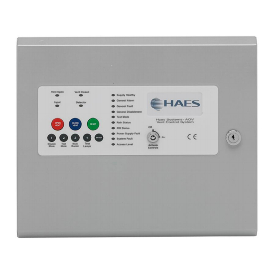
Page 36: Panel Controls & Indications
After activation by code entry, controls will automatically deactivate again after 2 minutes and the panel will return to standby mode. The test lamps and mute buzzer functions are operational without the need to activate controls. Approved Document Ref: UI-SZAOV-01 Issue 2.01... -
Page 37: Status Led Indicators
Rain Status Rain input is active Rain input is faulty or disabled PIR Status PIR input is active PIR input is faulty or disabled Power Supply Fault Mains Input fault Battery or Charger fault Approved Document Ref: UI-SZAOV-01 Issue 2.01... -
Page 38: Keypad
Also has the numeric value 4 for code entry. ENTER: This button is used to confirm code entries. Some buttons and indicators have other functions within the engineering facilities. These functions are described in the relevant sections. Approved Document Ref: UI-SZAOV-01 Issue 2.01... -
Page 39: Disable Mode
All disabled circuits and the General Disablement will now be indicated by a steady LED. To enable the circuits again, repeat the above process using the Disable Mode button to select the circuit and the ENTER button to remove the disablement. Approved Document Ref: UI-SZAOV-01 Issue 2.01... -
Page 40: Test Mode
System Fault recovery - System Fault LED pulsing and General Fault LED pulsing along with a pulsed buzzer (fault tone), a system fault has occurred and the affected board has recovered. The indication will remain until the panel is reset. Approved Document Ref: UI-SZAOV-01 Issue 2.01... -
Page 41: Service & Maintenance
It is the responsibility of the system user to ensure it is regularly serviced and maintained in good working order. Approved Document Ref: UI-SZAOV-01 Issue 2.01... -
Page 42: Schedule Of Testing
SCHEDULE OF TESTING SCHEDULE OF TESTING This section to be used to record ALL weekly tests of the fire alarm system Date & Device Tested & Initials of Comments (if any) Location Tester Time of Test Approved Document Ref: UI-SZAOV-01 Issue 2.01... - Page 43 Single zone AOV User Manual SCHEDULE OF TESTING Date & Device Tested & Initials of Comments (if any) Location Tester Time of Test Approved Document Ref: UI-SZAOV-01 Issue 2.01...
- Page 44 Single zone AOV User Manual SCHEDULE OF TESTING Date & Device Tested & Initials of Comments (if any) Location Tester Time of Test Approved Document Ref: UI-SZAOV-01 Issue 2.01...
- Page 45 www.haes-tech.com...
Need help?
Do you have a question about the SZAOV and is the answer not in the manual?
Questions and answers