
Related Manuals for Haes Excel-32


Summary of Contents for Haes Excel-32
- Page 1 EN54 APPROVED 16 - 32 ZONE CONVENTIONAL CONTROL PANEL 810a/08 Quick Start Guide Full manual available from www.haes-systems.com Approved Document UI-XL32-02 Issue 1.0 www.acornfiresecurity.com...
- Page 2 0832 Haes Systems Ltd, Columbia House, Packet Boat Lane, Cowley Peachey, Uxbridge, UB8 2JP Model Number CPR Number XL32, 16 - 32 zone conventional panel XL32-16/24/32 0832-CPR-F0837 European Standard EN54-2 : 1997 + A1 : 2006 Control and indicating equipment for fi re detection and fi re alarm systems for buildings.
-
Page 3: Table Of Contents
www.acornfiresecurity.com CONTENTS Page ABOUT THIS PANEL CABINET DETAILS MAIN PCB TERMINALS TECHNICAL SPECIFICATION POWER SUPPLY MODULE INSTALLATION SAFETY ESD PRECAUTIONS GENERAL SETUP & PROGRAMMING LEVEL 3 ENGINEERING MODE LEVEL 3 ENGINEERING OPTIONS INDEX OPERATING PANEL CONTROLS & INDICATIONS DISABLE MODE TEST MODE FAULT DIAGNOSIS FUNCTIONALITY DURING A SYSTEM FAULT... -
Page 4: About This Panel
www.acornfiresecurity.com ABOUT THIS PANEL CABINET 107mm 130mm Fire Detection System 410mm 465mm 400mm 450mm 450mm Quiesecent and alarm current details for standby battery calculations Models Standby Current Alarm Current XL32-16 205mA 300mA XL32-24 270mA 365mA XL32-32 320mA 415mA TPCA05 5.2mA XL32 Quick Start Guide Approved Document Ref: UI-XL32-02 Issue 1.0 www.acornfiresecurity.com... -
Page 5: Main Pcb Terminals
www.acornfiresecurity.com ABOUT THIS PANEL MAIN PCB TERMINALS 28V 0V FIRE FAULT SNDR1 SNDR2 SNDR3 SNDR4 ZONE1 ZONE2 ZONE3 ZONE4 ZONE5 ZONE6 ZONE7 ZONE8 ZONE9 ZONE10 ZONE11 ZONE12 ZONE13 ZONE14 ZONE15 ZONE16 + - + - + - + - + - + - + - + - C NC NO C NC NO... -
Page 6: Technical Specification
www.acornfiresecurity.com ABOUT THIS PANEL TECHNICAL SPECIFICATION Electrical Specifi cation Inputs & Outputs - TPCA11-16/24/32 Main PCB Terminal capacity 0.5mm to 2.5mm solid or stranded wire. PSU TX/RX Power supply data control lines. RS232 data. PSU Input A +/-, B +/- 28vdc supply input. -
Page 7: Power Supply Module
www.acornfiresecurity.com ABOUT THIS PANEL POWER SUPPLY MODULE Power Supply Specifi cation Mains supply 230vac +10% / -15% 50Hz max current 1.9A Mains supply fuse 3.15 Amp (F3.15A 250V) Not accessible for servicing. Internal to switch mode power unit Internal power supply rating 5.0 Amps total including battery charging Maximum load shared between outputs = 5A... -
Page 8: Installation
www.acornfiresecurity.com INSTALLATION SAFETY Suppliers of articles for use at work are required under section 6 of the Health and Safety at Work Act 1974 Suppliers of articles for use at work are required under section 6 of the Health and Safety at Work Act 1974 to ensure as reasonably as is practical that the article will be safe and without risk to health when properly to ensure as reasonably as is practical that the article will be safe and without risk to health when properly used. -
Page 9: Esd Precautions
www.acornfiresecurity.com INSTALLATION ESD PRECAUTION Electronic components are vulnerable to damage by Electrostatic Discharges (ESD). An ESD wrist strap, Electronic components are vulnerable to damage by Electrostatic Discharges (ESD). An ESD wrist strap, suitably grounded, should be worn at all times when handling pcbs. These wrist straps are designed to suitably grounded, should be worn at all times when handling pcbs. -
Page 10: Setup & Programming
RS GD FLT FR + - + - ZONE17 ZONE18 ZONE19 ZON INPUTS SW -V OUTPUTS For detailed programming instructions please download the full instruction manual (UI-XL32-01) at www.haes-systems.com XL32 Quick Start Guide Approved Document Ref: UI-XL32-02 Issue 1.0 www.acornfiresecurity.com... - Page 11 www.acornfiresecurity.com SETUP & PROGRAMMING PROGRAMMING OPTIONS INDEX Option/Setting Description Code(s) View History View the last 40 events 1111 Set Fault Buzzer Volume Set the fault buzzer volume to high or low 2224 Clear All Disablements Remove all disablements which have been set for any 1121 zone, sounder circuit, output or delay Initialise Factory Settings...
-
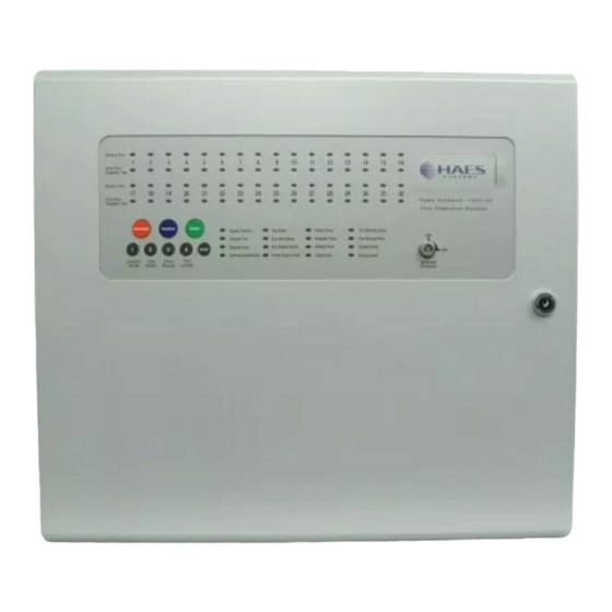
Page 12: Operating
www.acornfiresecurity.com OPERATING PANEL CONTROLS & INDICATIONS Zonal Fire & Fault Indicator LEDs Zones in Fire Zone Fault Disabled / Test Zones in Fire Zone Fault Fire Detection System Disabled / Test RESOUND SILENCE RESET Test Mode Delay Status Fire Routing Active Supply Healthy Sounder Status Repeater Fault... - Page 13 www.acornfiresecurity.com OPERATING Status LED Indicators LED On LED Pulsing Zones in Fire 1 - 32 Indicates alarm condition in zone. Zone Fault/Disabled/Test Indicates zone circuit is disabled or in test Indicates a fault in the zone circuit. 1 - 32 mode.
-
Page 14: Disable Mode
www.acornfiresecurity.com OPERATING DISABLE MODE Disable Mode is used to disable or isolate individual zone circuits or all sounder circuits, all auxiliary outputs and any delays to outputs. To initialise Disable Mode fi rstly activate the controls by turning RESOUND SILENCE RESET the key switch or by entering the four digit code. -
Page 15: Test Mode
www.acornfiresecurity.com OPERATING TEST MODE Test Mode is used when testing the fi re alarm system. In test mode the devices in the zone(s) in test, detectors and call points etc, can be activated and the panel will automatically reset, enabling the system to be tested by one person. -
Page 16: Fault Diagnosis
www.acornfiresecurity.com OPERATING FAULT DIAGNOSIS If the panel has detected a fault on the system the General Fault LED will be illuminated and the internal fault buzzer will sound. Secondary LEDs will also be illuminated depending on the location of the fault. Pressing and holding the ENTER button will reveal more detailed information about the loction and type of fault. -
Page 17: Functionality During A System Fault
www.acornfiresecurity.com OPERATING FUNCTIONALITY DURING A SYSTEM FAULT A system fault is indicated when a processor controlling a function in the panel has a watchdog time out or processor failure. In the event of a system fault the particular board affected may not be functional. The following indications may be observed. -
Page 18: Service & Maintenance
www.acornfiresecurity.com SCHEDULE OF TESTING This Section To Be Used To Record ALL Weekly Tests Of The Fire Alarm System DDATE & DEVICE TESTED & COMMENTS INITIALS OF LOCATION (IF ANY) TESTER TIME OF TEST XL32 Quick Start Guide Approved Document Ref: UI-XL32-02 Issue 1.0 www.acornfiresecurity.com... - Page 19 www.acornfiresecurity.com SCHEDULE OF TESTING This Section To Be Used To Record ALL Weekly Tests Of The Fire Alarm System DDATE & DEVICE TESTED & COMMENTS INITIALS OF LOCATION (IF ANY) TESTER TIME OF TEST XL32 Quick Start Guide Approved Document Ref: UI-XL32-02 Issue 1.0 www.acornfiresecurity.com...
- Page 20 www.acornfiresecurity.com SCHEDULE OF TESTING This Section To Be Used To Record ALL Weekly Tests Of The Fire Alarm System DDATE & DEVICE TESTED & COMMENTS INITIALS OF LOCATION (IF ANY) TESTER TIME OF TEST XL32 Quick Start Guide Approved Document Ref: UI-XL32-02 Issue 1.0 www.acornfiresecurity.com...
- Page 21 www.acornfiresecurity.com SCHEDULE OF TESTING This Section To Be Used To Record ALL Weekly Tests Of The Fire Alarm System DDATE & DEVICE TESTED & COMMENTS INITIALS OF LOCATION (IF ANY) TESTER TIME OF TEST XL32 Quick Start Guide Approved Document Ref: UI-XL32-02 Issue 1.0 www.acornfiresecurity.com...
-
Page 22: False Alarms, Faults & Engineer Visit Log Book
www.acornfiresecurity.com FALSE ALARMS, FAULTS & ENGINEERS VISITS Fault/Reason For Action Taken Date Work Completed Engineer’s Details Call-Out XL32 Quick Start Guide Approved Document Ref: UI-XL32-02 Issue 1.0 www.acornfiresecurity.com... - Page 23 www.acornfiresecurity.com FALSE ALARMS, FAULTS & ENGINEERS VISITS Fault/Reason For Action Taken Date Work Completed Engineer’s Details Call-Out XL32 Quick Start Guide Approved Document Ref: UI-XL32-02 Issue 1.0 www.acornfiresecurity.com...
- Page 24 www.acornfiresecurity.com FALSE ALARMS, FAULTS & ENGINEERS VISITS Fault/Reason For Action Taken Date Work Completed Engineer’s Details Call-Out XL32 Quick Start Guide Approved Document Ref: UI-XL32-02 Issue 1.0 www.acornfiresecurity.com...
-
Page 25: User Instructions
www.acornfiresecurity.com USER INSTRUCTIONS If an alarm condition is present YOU MUST FOLLOW YOUR NORMAL FIRE DRILL PROCEDURES. A responsible person should then:- 1. 1. Check the control panel to see which area or zone has caused the system to go into alarm. This will Check the control panel to see which area or zone has caused the system to go into alarm. - Page 26 www.acornfiresecurity.com www.acornfiresecurity.com...
Need help?
Do you have a question about the Excel-32 and is the answer not in the manual?
Questions and answers