RenewAire HE ERV Series Installation, Operation And Maintenance Manual
Hide thumbs
Also See for HE ERV Series:
- Installation, operation and maintenance manual (36 pages) ,
- Installation, operation and maintenance manual (32 pages)

Subscribe to Our Youtube Channel
Related Manuals for RenewAire HE ERV Series


Summary of Contents for RenewAire HE ERV Series
- Page 1 HE SERIES ERV Installation, Operation and Maintenance Manual HE1.5XRT Model: HE1.5XRT shown...
- Page 2 HE-Series Outdoor WARNING AVERTISSEMENT Standard HE1.5XRT with single phase original equipment Le HE1.5XRT avec moteurs d’équipement d’origine mono- motors are NOT suitable for use with solid state speed phasés ne convient pas pour une utilisation avec regulateur control. de vitesse electronique. Three phase motors are NOT suitable for use with solid Moteurs de trois phase ne convient pas pour utilisation state speed control.
- Page 3 Locate the RenewAire unit label found on the outside of the unit. contractor. The completed NOTE: This information is for purposes of identifying the unit-specific option data from the document is to be turned Option Code.
- Page 4 Amps Protection Amps Device Device Single 14.6 208-230 Single 3.3-3.4 Single 208-230 Three 2.2-2.2 2.2 - 2.2 Three Specifications may be subject Specifi cations may be subject to change without notice. to change without notice. RENEWAIRE.COM 1.800.627.4499 1.800.627.4499...
- Page 5 Specifications may be subject to change without notice. FOR THE MOST COMPLETE AND CURRENT INFORMATION VISIT RENEWAIRE.COM 1.800.627.4499...
- Page 6 SPECIFICATIONS & DIMENSIONS Specifications may be subject to change without notice. RENEWAIRE.COM 1.800.627.4499 1.800.627.4499...
- Page 7 HE1X Outdoor T H I S P A G E I S I N T E N T I O N A L LY L E F T B L A N K . THIS PAGE IS INTENTIONALLY LEFT BLANK 1.800.627.4499...
-
Page 8: Table Of Contents
TABLE OF CONTENTS HE-Series Outdoor 1.0 OVERVIEW 5.5 EXTERNAL CONTROL CONNECTIONS .....23 5.5.1 Single 2-Wire Control, Unpowered ........23 1.1 DESCRIPTION ............11 5.5.2 Control Sending 24 VAC “On” Signal .........23 5.5.3 Control System with two Non-Powered Relay Contacts ..23 1.2 AIRFLOW ..............12 5.5.4 Control System Sending two 24 VAC “On”... - Page 9 TABLE OF CONTENTS HE-Series Outdoor TABLE OF ILLUSTRATIONS Figure 1.2.0 Airflow Orientations ....................... 12 Figure 2.4.0 E-Box with Motor Starters ..................... 13 Figure 3.2.0 HE1.5XRT Weights and COGS ..................15 Figure 4.2.0 Service Clearances, Top View ..................16 Figure 5.3.0 E-Box Wiring Entry Points ....................19 Figure 5.4.0 HE1.5XRT Single Phase Unit, Standard ................21 Figure 5.4.1 HE1.5XRT Three Phase Unit, Standard ................21 Figure 5.4.2 HE1.5XRT Single Phase Unit, Independent Blower Control ..........22...
- Page 10 6: Unit Control "A" not available with Unit Control Enhancements Codes "1", "2", "3", & "4". 7: Unit Control "V" not available with Phase Code "1" (Single Phase). For Technical Support E-mail: RenewaireSupport@renewaire.com To Place an Order E-mail: RenewaireOrders@renewaire.com 1.800.627.4499...
-
Page 11: Overview
Each ERV has two electric blowers, one for each airstream. Fan speeds can be either single speed, or they can be variable speed, controlled by VFDs, a RenewAire Commercial Controller or by a BMS. There are a number of different control devices available to control the operation or speed of the unit fans. -
Page 12: Airflow
OVERVIEW HE-Series Outdoor 1.2 AIRFLOW There are four different airflow options for the HE1.5XRT. They are: HE1.5XRTV HE1.5XRTR HE1.5XRTF HE1.5XRTH HERT except 6x 8x, LERT HERT except 6x 8x, LERT All four configurations include attached hoods for the OA and EA airstreams. The airflow configuration is indicated by digit 9 of the Configuration Code. -
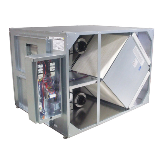
Page 13: Component Descriptions
DISCONNECT SWITCH GROUND BUS FIGURE 2.4.0 E-BOX WITH MOTOR STARTERS 2.5 FILTERS www.renewaire.com (800) 627- 4499 support@renewaire.com All HE1.5XRT units come equipped with four MERV 8 pleated filters. MERV 13 filters can be ordered as an accessory and are shipped loose. -
Page 14: Factory Installed Options
Any discovered shipping damage should be immediately reported to the RenewAire sales rep and the damage must be recorded on the Bill Of Lading, prior to signing for acceptance of the shipment. -
Page 15: Receiving
Upon receipt of the HE1.5XRT, inspect the unit for obvious external damage. If damage is 4/22/09 MF Scale: 1" = 24" HE1.5XRT Corner Weights SPECIFICATIONS SUBJECT observed, take digital pictures and report the damage to your RenewAire representative. Note TO CHANGE WITHOUT NOTICE. Do not scale drawing MAY18- MHK 4/22/09 MF Scale: 1"... -
Page 16: Unit Placement
The HE1.5XRT is designed for installation outdoors, typically on a roof top. The preferred mounting method is to place the ERV on an optional manufactured curb, designed for the specific unit. RenewAire recommends the use of optional curb clips to provide substantial resistance to wind damage. -
Page 17: Sound Attenuation
UNIT PLACEMENT HE-Series Outdoor 4.3 SOUND ATTENUATION Take these simple steps to attenuate noise from the unit. 4.3.1 Outside the Building The exhaust hood is the primary source of noise outside the building. When practical, orient the exhaust air hood to point away from houses or public areas. 4.3.2 At the Curb Cut the holes in the roof deck to fit closely around the duct(s) passing through the roof deck. -
Page 18: Installation
(provided) on all bearing surfaces on the curb. Optional installation of owner-provided rails (HE1.5XRTH only): RenewAire recommends that all HE1.5XRT units be installed on a RenewAire-supplied curb that is manufactured to match individual units. The only unit that may be installed on owner-supplied mountings rails is the HE1.5XRTH. -
Page 19: Duct Insulation
HIGH-VOLTAGE SUPPLY tronique. WIRING IS TERMINATED ON THE TOP OF THE DISCONNECT SWITCH LOW-VOLTAGE HIGH-VOLTAGE SUPPLY CONTROL WIRING WIRING ENTRY ENTRY FIGURE 5.3.0 E-BOX WIRING ENTRY POINTS www.renewaire.com (800) 627- 4499 support@renewaire.com 1.800.627.4499... -
Page 20: Low Voltage Control System
INSTALLATION HE-Series Outdoor 5.3.2 Low Voltage Control System This ERV is provided with a Class II 24 VAC power supply system that operates the unit’s contactor(s) for HE1.5XRT. The ERV’s 24 VAC Power Supply can also be used to power the externally-installed controls system: up to 8 VA of power is available. -
Page 21: Wiring Schematics
24 VAC Supply Fan Relay 24 VAC Transformer FIGURE 5.4.0 HE1.5XRT SINGLE PHASE UNIT, STANDARD REV. DATE NAME CHANGES RenewAire Input Power 208-230 VAC, 3 Phase HE1.5JRTx-x11,15,19xx--xAxTx-xx Family 460 VAC, 3 Phase 8/2/2018 austine Added Wire Color Labels No Damper... -
Page 22: Figure 5.4.2 He1.5Xrt Single Phase Unit, Independent Blower Control
Relay Relay 24 VAC 24 VAC Transformer FIGURE 5.4.2 HE1.5XRT SINGLE PHASE UNIT, WITH INDEPENDENT BLOWER CONTROL REV. DATE NAME CHANGES RenewAire Input Power HE1.5JRTx-x11,15,19xx--xDxTx-xx Family 208-230 VAC, 3 Phase 8/2/2018 austine Added Wire Color Labels No Damper Description 460 VAC, 3 Phase... -
Page 23: External Control Connections
INSTALLATION HE-Series Outdoor 5.5 EXTERNAL CONTROL CONNECTIONS NOTE: The sim- 5.5.1 Single 2-Wire Control, Unpowered plified schematics below show only Use the schematic shown in Figure 5.5.0 if the control requires no power to operate and acts the relevant portions of like a simple on/off switch. -
Page 24: Control System Sending Two 24 Vac "On" Signals (From An External Power Source)
INSTALLATION HE-Series Outdoor 5.5.4 Control System Sending two 24 VAC “On” Signals (from an external power source) Use Figure 5.5.3 only if the ERV has Independent Blower Control: Make sure the jumper is NOT installed between Terminals 2 and 3. Now you safely can apply one of the 24 VAC signals to Terminals 3 and 4 to operate the ERV’s isolation relay for the Fresh Air Blower. -
Page 25: Control System Operating Isolation Dampers With End Switches
INSTALLATION HE-Series Outdoor 5.5.8 Control System Operating Isolation Dampers with End Switches Use Isolation Dampers with electrically separate end switches. The end switches are used to separately control the ERV unit’s Isolation Relays. Also, specify the ERV with Independent Blower Control. This ensures that each damper is open before the respective blower starts up. Because the ERV’s Motor Starters will only be operating once the Dampers are open, the power draw of the Damper Actuators is allowed to be as much as 35 VA while opening (including power draw of the external control system, if any). -
Page 26: To Field Convert The Outlet Opening
FIGURE 5.7.0 EXAMPLE OF CONVERTING VERTICAL OPENING TO HORIZONTAL OPENING After completion of the field conversion: Clean out the interior of the unit to remove any debris. www.renewaire.com (800) 627- 4499 support@renewaire.com Install energy exchanger cores, filters, and core strap. -
Page 27: Operation
OPERATION HE-Series Outdoor 6.0 OPERATION 6.1 PRINCIPLE OF OPERATION The HE1.5XRT has one basic purpose: to exhaust air from a structure and bring in fresh air from outside, while transferring heating or cooling energy from the exhaust air to the fresh air. The HE1.5XRT is a very simple device, and will accomplish this purpose as long as the blower is able to move air through the enthalpic core. -
Page 28: Balancing Airflow
OPERATION HE-Series Outdoor 6.3 UNIT START-UP 6.3.1 Fixed-Speed Units Most fixed-speed units do not have any external controlling signals and only require turning on the disconnect switch, located on the E-Box. When the disconnect switch is turned ON, any dampers will first move into their correct operating positions and then power is suppled to the motor contactors, causing the fans to run. -
Page 29: Filter Pressure Drop
14+16x20x2 MERV 8 (IOM) 375–1400 CFM. FIGURE 6.4.0 PRESSURE PORT LOCATIONS DIFFERENTIAL STATIC ACROSS CORE DSP VS. CFM www.renewaire.com (800) 627- 4499 support@renewaire.com DP (H DSP 0.10 0.15 0.20 0.25 0.30 0.35 0.40 0.45 0.50 0.55 0.60 0.65 0.70 0.75 0.80 0.85... -
Page 30: Normal Operation
7.0 MAINTENANCE RenewAire ERVs are built to operate with minimal maintenance. After unit commissioning, the primary areas of attention are the air filters and annual vacuuming of the enthalpic cores. -
Page 31: Filters
MAINTENANCE HE-Series Outdoor 7.4 FILTERS Inspection and replacement of air filters is the most frequent maintenance issue. For units that do not have filter air pressure differential sensors, filters must be visually inspected monthly, as a minimum. If a filter looks discolored or dirty, REPLACE IT! When installing new filters, DO NOT USE filter sprays. -
Page 32: Maintenance Records
MAINTENANCE HE-Series Outdoor 7.7 MAINTENANCE RECORDS MAINTENANCE LOG ENTER DATES OF SERVICE OA FILTER RA FILTER INSPECTION/ CLEAN CLEAN INITIALS CHANGE CHANGE CLEANING CORE BLOWERS 1.800.627.4499... - Page 33 MAINTENANCE HE-Series Outdoor MISCELLANEOUS SERVICE NOTES DATE SERVICE INITIALS 1.800.627.4499...
-
Page 34: Service Parts
MAINTENANCE HE-Series Outdoor 7.8 SERVICE PARTS FIGURE 7.8.0 HE1.5XRT SERVICE PARTS www.renewaire.com (800) 627- 4499 support@renewaire.com 1.800.627.4499... -
Page 35: Troubleshooting
FACTORY ASSISTANCE HE-Series Outdoor 8.0 TROUBLESHOOTING If problems occur with a RenewAire ERV, the primary resources for troubleshooting are the unit as-built wiring schematics and the Sequence Of Operation (SOO) for each control scheme. 9.0 FACTORY ASSISTANCE In the unlikely event that you need assistance from the factory for a specific issue, make sure that you have the information called for in the Unit Information page in the front of this manual. - Page 36 About RenewAire For over 30 years, RenewAire has been a pioneer in enhancing indoor air quality (IAQ) in commercial and residential buildings of every size. This is achieved while maximizing sustainability through our fifth-generation, static-plate, enthalpic-core Energy Recovery Ventilators (ERVs) that optimize energy efficiency, lower capital costs via load reduction and decrease operational expenses by minimizing equipment needs, resulting in significant energy savings.
Need help?
Do you have a question about the HE ERV Series and is the answer not in the manual?
Questions and answers