Sign In
Upload
Manuals
Brands
RenewAire Manuals
Fan
HE ERV Series
User Manuals: RenewAire HE ERV Series Ventilator
Manuals and User Guides for RenewAire HE ERV Series Ventilator. We have
3
RenewAire HE ERV Series Ventilator manuals available for free PDF download: Installation, Operation And Maintenance Manual
RenewAire HE ERV Series Installation, Operation And Maintenance Manual (36 pages)
Brand:
RenewAire
| Category:
Fan
| Size: 5 MB
Table of Contents
Table of Contents
8
1 Overview
11
Description
11
Airflow
12
Figure 1.2.0 Airflow Orientations
12
2 Component Descriptions
13
Cabinet
13
Enthalpic Cores
13
Fan/Motor Assemblies
13
E-Box
13
Filters
13
Figure 2.4.0 E-Box with Motor Starters
13
Factory Installed Options
14
3 Shipping/Receiving/Handling
14
Unit Weights and Dimensions
14
Unit Dimensions and Weight
14
Maximum Shipping Dimensions and Weight
14
Rigging and Center of Gravity
14
HE1.5XRT Hoisting Weights and COG
14
Receiving
15
Storage
15
Figure 3.2.0 HE1.5XRT Weights and COGS
15
4 Unit Placement
16
Before You Begin
16
Service Clearances
16
Figure 4.2.0 Service Clearances, Top View
16
Sound Attenuation
17
Outside the Building
17
At the Curb
17
Ducts
17
Radiated Noise
17
Connecting Horizontal Ducts to Unit
17
5 Installation
18
Curb Specifications
18
Ductwork
18
Inside Ductwork System
18
Duct Insulation
19
Use Dampers to Set and Balance Airflow Rates
19
Electrical Requirements
19
Electronically Commutated Motors
19
Figure 5.3.0 E-Box Wiring Entry Points
19
Low Voltage Control System
20
How to Reset the 24 VAC Circuit Breaker
20
Limits of Power Output
20
Wiring Schematics
21
Figure 5.4.0 HE1.5XRT Single Phase Unit, Standard
21
Figure 5.4.1 HE1.5XRT Three Phase Unit, Standard
21
Figure 5.4.2 HE1.5XRT Single Phase Unit, Independent Blower Control
22
Figure 5.4.3 HE1.5XRT Three Phase Unit, Independent Blower Control
22
External Control Connections
23
Single 2-Wire Control, Unpowered
23
Control Sending 24 VAC "On" Signal
23
Control System with Two Non-Powered Relay Contacts
23
Figure 5.5.0 a Switch or Non-Powered Control Using Unit's 24 VAC Power Supply
23
Figure 5.5.1 24 VAC from an External Source
23
Figure 5.5.2 Two External Non-Powered Relay Contacts
23
Control System Sending Two 24 VAC "On" Signals (from an External Power Source)
24
Control Operating on Unit's 24 VAC Power Supply
24
Control on Separate Power Supply
24
Control System on Separate Power Supply; Independent Blower Control
24
Figure 5.5.3 Two External Relay Contacts Supplying 24 VAC from an External Source
24
Figure 5.5.4 an External Control Using Unit's 24 VAC Power Supply
24
Control System Operating Isolation Dampers with End Switches
25
Quick Start for Testing Correct 3Ph Wiring
25
Field Conversion of Openings
25
To Field Convert the Inlet Opening
25
To Field Convert the Outlet Opening
26
Figure 5.7.0 Example of Converting Vertical Opening to Horizontal Opening
26
6 Operation
27
Principle of Operation
27
Pre-Start-Up
27
Verify Voltages
27
Verify Transformer Wiring
27
Inspect Filters
27
Inspect Foam Gasketing
27
Inspect Fans
27
Inspect and Clean the Cabinet Interior
27
Inspect Ductwork Connections
27
Balancing Airflow
28
Filter Pressure Drop
29
Figure 6.4.0 Pressure Port Locations
29
Figure 6.4.1 Initial Pressure Drop of MERV 8 Filters, Supplied with this Unit
29
Figure 6.4.2 Initial Pressure Drop of MERV 13 Filters, Available as an Accessory
29
Normal Operation
30
Extreme Cold Operation
30
7 Maintenance
30
Maintenance 24 Hrs. after Start-Up
30
Maintenance 30 Days after Start-Up
30
Maintenance Schedule
30
Filters
31
Fan Motors
31
Enthalpic Core
31
Enthalpic Core Maintenance
31
Enthalpic Core Removal
31
Enthalpic Core Replacement
31
Maintenance Records
32
Service Parts
34
Figure 7.8.0 HE1.5XRT Service Parts
34
8 Troubleshooting
35
9 Factory Assistance
35
Advertisement
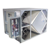
RenewAire HE ERV Series Installation, Operation And Maintenance Manual (32 pages)
Brand:
RenewAire
| Category:
Heating System
| Size: 5 MB
Table of Contents
Table of Contents
8
1 Overview
11
Description
11
Airflow
12
2 Component Descriptions
12
Cabinet
12
Enthalpic Cores
12
Fan/Motor Assemblies
12
E-Box
12
Figure 1.2.0 Airflow Orientations
12
Filters
13
Factory Installed Options
13
3 Shipping/Receiving/Handling
13
Unit Weights and Dimensions
13
Unit Dimensions and Weight
13
Maximum Shipping Dimensions and Weight
13
Figure 2.4.0 E-Box with Motor Starters
13
Rigging and Center of Gravity
14
HE1.5XINH Hoisting Weights and COG
14
HE1.5XINV Hoisting Weights and COG
14
Receiving
14
Figure 3.2.1 HE1.5XINH Weights and COGS
14
Storage
15
4 Unit Placement
15
Before You Begin
15
Service Clearances
15
Figure 4.2.0 HE1.5XINH Service Clearances
15
Figure 4.2.1 HE1.5XINV Service Clearances
15
Sound Attenuation
16
Outside the Building
16
Ducts
16
Radiated Noise
16
5 Installation
16
Ductwork
16
Inside Ductwork System
16
Duct Insulation
16
Floor Installation
16
Suspended Mount
17
Electrical Requirements
17
Electronically Commutated Motors
17
Low Voltage Control System
17
How to Reset the 24 VAC Circuit Breaker
18
Limits of Power Output
18
Wiring Schematics
19
Figure 5.5.0 HE1.5XIN Single Phase Unit, Standard
19
Figure 5.5.1 HE1.5XIN Three Phase Unit, Standard
19
Figure 5.5.2 HE1.5XIN Single Phase Unit, Independent Blower Control
20
Figure 5.5.3 HE1.5XIN Three Phase Unit, Independent Blower Control
20
External Control Connections
21
Single 2-Wire Control, Unpowered
21
Control Sending 24 VAC "On" Signal
21
Control System with Two Non-Powered Relay Contacts
21
Figure 5.6.0 a Switch or Non-Powered Control Using Unit's 24 VAC Power Supply
21
Figure 5.6.1 24 VAC from an External Source
21
Figure 5.6.2 Two External Non-Powered Relay Contacts
21
Control System Sending Two 24 VAC "On" Signals (from an External Power Source)
22
Control Operating on Unit's 24 VAC Power Supply
22
Control System Operating Isolation Dampers with End Switches
22
Figure 5.6.3 Two External Relay Contacts Supplying 24 VAC from an External Source
22
Figure 5.6.4 an External Control Using Unit's 24 VAC Power Supply
22
Quick Start for Testing Correct 3Ph Wiring
23
Field Conversion of Openings
23
To Field Convert the Inlet Opening
23
To Field Convert the Outlet Opening
24
Figure 5.7.0 Example of Converting Openings
24
6 Operation
25
Principle of Operation
25
Pre-Start-Up
25
Verify Voltages
25
Verify Transformer Wiring
25
Inspect Filters
25
Inspect Foam Gasketing
25
Inspect Fans
25
Inspect and Clean the Cabinet Interior
25
Inspect Ductwork Connections
25
Unit Start-Up
26
Fixed-Speed Units
26
Balancing Airflow
26
Figure 6.4.0 HE1.5XINH Pressure Port Locations, Typical
26
Figure 6.4.1 Initial Pressure Drop of MERV 8 Filters, Supplied with this Unit
27
Figure 6.4.2 Initial Pressure Drop of MERV 13 Filters, Available as an Accessory
27
Filter Pressure Drop
27
Normal Operation
28
Extreme Cold Operation
28
7 Maintenance
28
Maintenance 24 Hrs. after Start-Up
28
Maintenance 30 Days after Start-Up
28
Maintenance Schedule
28
Filters
29
Fan Motors
29
Enthalpic Core
29
Enthalpic Core Maintenance
29
Enthalpic Core Removal
29
Enthalpic Core Replacement
29
Maintenance Records
30
Service Parts
31
8 Troubleshooting
31
9 Factory Assistance
31
Figure 7.8.0 HE1.5XIN Service Parts
31
RenewAire HE ERV Series Installation, Operation And Maintenance Manual (36 pages)
Brand:
RenewAire
| Category:
Fan
| Size: 5 MB
Table of Contents
Table of Contents
8
1 0 Overview
11
Airflow
11
Airflow in HE2XINH
12
Airflow in HE2XINV
12
Description
11
2 Component Descriptions
12
Cabinet
12
Enthalpic Cores
12
Fan/Motor Assemblies
12
E-Box
13
Filters
13
Factory Installed Options
13
3 Shipping/Receiving/Handling
13
Unit Weights and Dimensions
14
Unit Dimensions and Weight
14
Shipping Dimensions and Weight
14
Rigging and Center of Gravity
14
HE2XINH Hoisting Weights and COG
14
HE2XINV Hoisting Weights and COG
15
Receiving
15
Storage
15
4 Unit Placement
15
Before You Begin
15
Service Clearances
16
Sound Attenuation
16
Outside the Building
16
Ducts
16
Radiated Noise
17
Aerodynamic (Velocity) Noise
17
5 Installation
17
Ductwork
17
Ductwork: All Units
17
Indoor Sound Attenuation
17
Floor Installation
17
Suspended Mount
17
Electrical Requirements
18
Factory-Recommended Electric Service Entry
18
Low Voltage Control System
19
How to Reset the 24 VAC Circuit Breaker
19
Limits of Power Output
19
Electric Wiring Schematic
20
Connections
22
Single 2-Wire Control, Unpowered
22
Single 2-Wire Control, Separate Power
22
Control Sending 24 VAC "ON" Signal
22
External Control Using ERV Power Supply
23
Control with 2 Non-Powered Relay Contacts
23
Control with 2 "ON" Signals, External Power
23
Quick-Start for Testing Correct 3Ph Wiring
24
6 Operation
24
Principle of Operation
24
Pre-Startup
24
Verify Voltages
24
Verify Transformer Wiring
24
Inspect Filters
24
Inspect Foam Gasketing
24
Inspect Belts and Verify Sheave Alignment
24
Inspect Fans
24
Unit Startup
25
Fixed-Speed Units
25
Balancing Airflows
25
All Fixed-Speed Units
26
Filter Pressure Drop
27
Sheave Adjustment
28
Variable-Speed Units
28
Normal Operation
28
Extreme Cold Operation
28
7 Maintenance
29
Maintenance 24 Hrs. after Start-Up
29
Maintenance 30 Days after Start-Up
29
Maintenance Schedule
29
Filters
29
Fan Motors
29
Belt Tension
29
Sheave Condition
30
Motor Cleanliness
30
Motor Lubrication
30
Enthalpic Cores
30
Enthalpic Core Maintenance
30
Enthalpic Core Removal
31
Enthalpic Core Replacement
31
Maintenance Records
32
Advertisement
Advertisement
Related Products
RenewAire HE1.5XRT
RenewAire HE2XINH
RenewAire HE3XRTH
RenewAire HE3XRTV
RenewAire HE1XRTC
RenewAire HE2XRTC
RenewAire HE1XINV
RenewAire HE4XINH
RenewAire HE2XRTH
RenewAire HE4XRTF
RenewAire Categories
Fan
Air Conditioner
Controller
Industrial Equipment
Heating System
More RenewAire Manuals
Login
Sign In
OR
Sign in with Facebook
Sign in with Google
Upload manual
Upload from disk
Upload from URL