RenewAire HE-Series Installation, Operation And Maintenance Manual
Enhanced commercial controls
Hide thumbs
Also See for HE-Series:
- Installation, operation and maintenance manual (152 pages) ,
- Supplemental installation manual for options (8 pages) ,
- Installation, operation and maintenance manual (28 pages)

Subscribe to Our Youtube Channel
Related Manuals for RenewAire HE-Series


Summary of Contents for RenewAire HE-Series
- Page 1 ENHANCED COMMERCIAL CONTROLS Installation, Operation and Maintenance Manual FOR EV450, HE-Series, and LE-Series Units Carel c.pCO Mini...
- Page 2 Enhanced Commercial Controls This manual applies to energy recovery ventilator (ERV) units with enhanced controls version 3.xx.xx. For previous versions refer to the older manual. The version number can be seen on the splash screen when the unit power is cycled. Newer units also have this version information in the Unit Status screens.
- Page 3 This control system is subject to periodic updates in firmware are to access the ERV control panel and the controller. Chang- and the User Manual itself. Please contact RenewAire Support es to the controller settings are to be made only by trained and at RenewAireSupport@RenewAire.com to determine if you...
- Page 4 In the unlikely event that factory assistance is ever required, information located on the unit label will be needed. Locate the RenewAire unit label found on the outside of the unit. NOTE: This information is for purposes of identifying the unit-specific option data from the Configuration Code.
- Page 5 "X" = 5HP (HE-3X, HE-4X, HE-6X, HE-8X only) For Technical Support E-mail: RenewaireSupport@renewaire.com "Y" = 7.5HP (HE-6X, HE-8X only) Digit 23: Other Options To Place an Order E-mail: RenewaireOrders@renewaire.com "Z" = 10HP (HE-8X only) "-" = None (Reserved) Digit 15: EA Horsepower (see Restrictions 7 & 19)
-
Page 6: Table Of Contents
TABLE OF CONTENTS Enhanced Commercial Controls 1.0 OVERVIEW 6.0 SPECIAL FEATURES 1.1 CONTROL SEQUENCE OVERVIEW ......10 6.1 FROST CONTROL ..........27 1.2 ENERGY RECOVERY BASICS ........10 6.2 SINGLE FAN MODE ..........28 1.3 TEMPERATURE SENSORS ........11 6.3 USE ROOM TEMP AND HUMIDITY RATHER THAN RETURN ............28 1.4 COMBINATION TEMPERATURE AND HUMIDITY SENSORS ..........12... - Page 7 14.2 TEMPERATURE SENSOR CURVE ......78 11.6 ADDING A BACNET LICENSE ........62 11.6.1 Obtaining a BACnet License ..........62 14.3 EV450 AND HE-SERIES FULL 11.6.2 Installing the BACnet License via Web Page ....62 CONFIGURATION CODE ........80 11.6.3 Installing the BACnet License via USB Drive ....63 14.4 LE-SERIES FULL CONFIGURATION CODE ....82...
- Page 8 14.6.1.1 ABB VFD Parameters ........... 86 14.6.1.2 View All Parameters ............ 86 14.5.1.3 Locking and Unlocking Parameters ......87 14.6.1.4 RenewAire Parameter Settings ........88 14.6.1.5 Motor Specific VFD Parameter Settings ......90 14.6.1.6 VFD Wiring to Controller ..........92 14.6.2 Lenze VFD Information ..........
- Page 9 TABLE OF CONTENTS Enhanced Commercial Controls TABLE OF ILLUSTRATIONS Figure 1.3.0 Duct Temperature Sensor ........11 Figure 1.4.0 Temperature and Humidity Sensor ......12 Figure 1.5.0 Sensor Locations in ERV units, HE2XINH Shown ..12 Figure 2.0.0 C.PCO Controller Buttons ........13 Figure 2.0.2 Optional Remote User Terminal (RUT) Button Locations ............
-
Page 10: Overview
1.1 CONTROL SEQUENCE OVERVIEW NOTE: This unit has a microprocessor The Renewaire ERV with enhanced controls provides outdoor air while saving energy by passing controller. It is com- the Exhaust Air through the energy recovery core to exchange energy with the incoming air,... -
Page 11: Temperature Sensors
OVERVIEW Enhanced Commercial Controls RenewAire energy recovery ventilators use static-plate, enthalpy-core heat exchangers that have no moving parts. During summer months, the hot and humid OA passes by the cooler, drier RA, lowing its temperature and humidity. During winter months, the cold and dry OA passes by the warmer, moister RA, raising its temperature and humidity. -
Page 12: Combination Temperature And Humidity Sensors
OVERVIEW Enhanced Commercial Controls 1.4 COMBINATION TEMPERATURE AND HUMIDITY SENSORS Humidity transducers are mounted in the OA and RA compartments and provide an output from 0–10VDC that is proportional to 0–100% Relative Humidity. FIGURE 1.4.0 TEMPERATURE AND HUMIDITY SENSOR 1.5 SENSOR LOCATIONS FILTER PRESSURE SENSORS... -
Page 13: Controller Overview
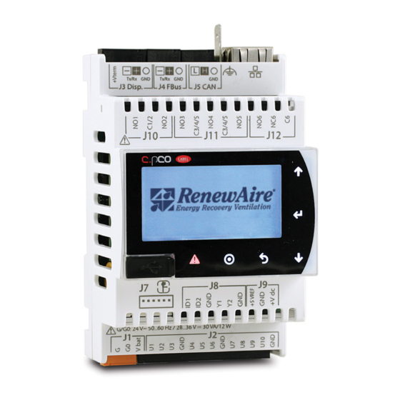
CONTROLLER OVERVIEW Enhanced Commercial Controls 2.0 CONTROLLER OVERVIEW The control utilizes the Carel c.pco (pronounced see-pee-ko) controller. C.pCO n° (03) 75.5°F Time 12:33 date: 07.06.2017 Up Button 24VAC Power Enter Button Universal inputs/outputs Down Button Power for RUT remote display Escape Button Remote display or Program Button... -
Page 14: Controller Access Methods
CONTROLLER OVERVIEW Enhanced Commercial Controls Pressing the PRG (program) button accesses the Service Menu or Login screen from any location in the user interface screens. The options that are available dynamically change depending on the configuration of the unit and the options installed on the unit. -
Page 15: Connecting Using Internal Web
CONTROLLER OVERVIEW Enhanced Commercial Controls The RUT (optional accessory, field-installed) plugs into the controller by means of a six wire cable with RJ12 jacks on each end. The six-wire cable is inserted in the RJ12 jack on the back of the RUT and the other end of the cable is inserted into the RJ12 adapter, found in the low voltage electrical compartment. -
Page 16: Setting The Pc Ip Address
CONTROLLER OVERVIEW Enhanced Commercial Controls You should see this web page. To get to the menu screens, click on RUT on the Menu Bar. 2.1.3 Setting the PC IP Address For those that are not familiar with changing their PC adapter settings, go into Network Setting in the Control Panel and Change Adapter Settings. -
Page 17: Using The Multikey Function Of The Web
CONTROLLER OVERVIEW Enhanced Commercial Controls Select Internet Protocol 4 and click on Properties. NOTE: When you are finished viewing the controller on your computer, remember to restore the original settings. Enter the IP address you want to use. It should not be identical to the controller IP address. The last octet of the IP address should be different. -
Page 18: Password Protected Menu Structure
GENERAL FLOW Enhanced Commercial Controls 2.2.2 Password Protected Menu Structure The password protected menu can be reached but pressing the PROG button and entering the password. The menus contain the following areas: Back Up and Restore—Contains the screens to back up your settings or return to factory defaults Unit Configuration—Main Unit Configuration Settings that determine which screens show up in other areas... -
Page 19: Unit Configuration
UNIT CONFIGURATION Enhanced Commercial Controls 4.0 UNIT CONFIGURATION 4.1 CONFIGURE GENERAL SETTING There are several general settings that are need for correct operation of the controller. 4.1.1 Setting the Time and Date It is important to have the correct time and date for alarm time stamps and logging. Set Refresh to YES, It will turn back to NO after changing the display to the current controller time and date. -
Page 20: Scheduler
UNIT CONFIGURATION Enhanced Commercial Controls 4.1.4 Scheduler Enable the scheduler, if desired. If you enable the scheduler, it will have to be set for “ON” for the unit to run along with all other “ON” conditions. Enable the scheduler by setting to YES. Set the schedule for each day. -
Page 21: Unit Operation And Fan Control
UNIT OPERATION Enhanced Commercial Controls NOTE: If you choose EV450 you will only see information for the supply fan as both fans are run from one motor. 5.0 UNIT OPERATION AND FAN CONTROL The primary purpose of the ERV unit is to provide 100% OA. The amount of air that it provides is based on the configuration of the supply and exhaust fans and whether the unit is running or not. -
Page 22: Digital Input (Id1) Unit On/Off
UNIT OPERATION Enhanced Commercial Controls The Unit status is shown on the bottom of this screen. More than one of these statuses may be valid at one time UNIT STATUS CONDITIONS STATUS SHOWN MEANING Unit on The unit is on and running. Unit switched off due to alarm The unit is off by a serious alarm. -
Page 23: Optional Smoke Detector
UNIT OPERATION Enhanced Commercial Controls 5.1.1.1 Optional Smoke Detector Normally field-installed on the discharge duct, near the furnace. FIGURE 5.1.0 SMOKE DETECTOR 5.1.1.2 Optional Motion Sensor Used for occupancy-based ventilation, hardwired to the low-voltage terminal strip. FIGURE 5.1.1 MOTION SENSOR (CEILING MOUNT) FIGURE 5.1.2 MOTION SENSOR (WALL MOUNT) 5.1.2 Optional Dampers The ERV unit has optional isolation dampers with end switches. -
Page 24: Current Sensors
UNIT OPERATION Enhanced Commercial Controls 5.1.4 Current Sensors NOTE: Current sen- Current sensors are installed on high voltage supply wires to sense current going to a fan motor. sors are calibrated They are used to prove the ON/OFF state of fan motors. for reduced fan speed at time of shipment from the factory. -
Page 25: Options For Supply Fan Control
UNIT OPERATION Enhanced Commercial Controls You can also see the pressure in this screen so that if it gets close to the alarm level you can change it at your convenience. 5.2 OPTIONS FOR SUPPLY FAN CONTROL Units with a VFD or ECM for the supply fan can control the fan for constant speed. 5.2.1 Constant Fan Speed Option The analog voltage command to the supply fan VFD or ECM can be set from the unit controller display or by the BMS. -
Page 26: Options For Exhaust Fan Control
UNIT OPERATION Enhanced Commercial Controls 5.3 OPTIONS FOR EXHAUST FAN CONTROL Units with a VFD or ECM for the exhaust fan can control the fan for fixed speed, or supply fan command tracking control. 5.3.1 Constant Fan Speed Option The analog voltage command to the exhaust fan VFD or ECM can be set from the unit controller display or by the BMS. -
Page 27: Special Features
SPECIAL FEATURES Enhanced Commercial Controls 6.0 SPECIAL FEATURES These features are not common but are available in the ERV controller. 6.1 FROST CONTROL ERV units utilize the optional bypass damper to bypass the core when it is very cold outside. This is usually used in northern states and Canada. -
Page 28: Single Fan Mode
Sensor 24 VAC Exh Fan Only Enable EF Only Enable 02-9-A EFEN2 Accy COM Sensor 24 VAC REV. DATE NAME CHANGES RenewAire shreyat Updated controller gnd connections 4/4/2022 DN-2,3-Jxxxxx33,34,35--xGxExx--xx_0 austine Updated Ground Locations 5/8/2020 5/5/2020 austine Added Any Alarm Output... -
Page 29: Flush Feature
SPECIAL FEATURES Enhanced Commercial Controls 6.4 FLUSH FEATURE The flush feature is used in conjunction with the scheduler function that allows you to set the unit into flush mode for specific time periods where the exhaust fan and supply fan will run at a % during this period. -
Page 30: Verifying I/O And Unit Wiring
I/O AND UNIT WIRING Enhanced Commercial Controls 7.0 VERIFYING I/O AND UNIT WIRING All of the I/O values should be verified and calibrated, if necessary. 7.1 VERIFYING ALL I/O THROUGH UNIT STATUS SCREENS All of the individual I/O are able to be viewed in one place by pressing “ENTER” when on this screen, which is located toward the and of Unit Status. -
Page 31: Sensor Inputs
I/O AND UNIT WIRING Enhanced Commercial Controls 7.3.1 Sensor Inputs SENSOR INTERMEDIATE CONTROLLER SENSOR TYPE TERMINALS TERMINALS TERMINALS Far Left (Red) U1 (Main) OA Temperature 2 (Black) X4-39 Sens COM GND TS2 Combined CAREL NTC/0– 3 (Red) X4-38 24VAC TS1 10VDC OA Humidity 4 (Black) -
Page 32: Digital Outputs
I/O AND UNIT WIRING Enhanced Commercial Controls 7.3.3 Digital Outputs Outputs in Grey are optional, and field-installed. Heating and cooling may be factory-installed or field-installed, depending upon the unit. OUTPUT INTERMEDIATE CONTROLLER OUTPUT TYPE TERMINALS TERMINALS TERMINALS X2-13 NO1 (Main) (See wiring SF Enable Dry Contact... -
Page 33: Sample Power Wiring Schematic
I/O AND UNIT WIRING Enhanced Commercial Controls 7.3.5 Sample Power Wiring Schematic NOTE: This wiring schematic is TYPICAL control wiring for a three phase, 208-230VAC and 460VAC input for models HE-2X, HE3X, HE-4X, HE- 6X, and HE-8X. A unit-spe- cific electrical schematic is found inside the access door to the core module. -
Page 34: Sample Control Wiring Schematic
I/O AND UNIT WIRING Enhanced Commercial Controls 7.3.6 Sample Control Wiring Schematic NOTE: This wiring schematic is TYPICAL control wiring for a three phase, 208-230VAC and 460VAC input for models HE-2X, HE3X, HE-4X, HE- 6X, and HE-8X. A unit-spe- cific electrical schematic is found inside the access door to the core module. -
Page 35: Sample Field Wiring Schematic
I/O AND UNIT WIRING Enhanced Commercial Controls 7.3.7 Sample Field Wiring Schematic NOTE: This wiring schematic is TYPICAL control wiring for a three phase, 208-230VAC and 460VAC input for models HE-2X, HE3X, HE-4X, HE- 6X, and HE-8X. A unit-spe- cific electrical schematic is found inside the access door to the core module. -
Page 36: Alarms And Troubleshooting
TROUBLESHOOTING Enhanced Commercial Controls 8.0 ALARMS AND TROUBLESHOOTING If the problem is caused by an alarm, the first step in troubleshooting is to view the Alarm screens. Press the Alarm button on the face of the controller to see all current alarms and what function or component is causing the alarm. -
Page 37: Resetting Alarms
TROUBLESHOOTING Enhanced Commercial Controls An alarm log screen looks like this. If the event is Stop, it shows the time that the alarm went away. If the event is Start, it shows the time that the alarm first occurred. There may be up to 50 entries. -
Page 38: Specific Alarms And Their Meaning
TROUBLESHOOTING Enhanced Commercial Controls The physical connection is made at the controller, it is terminated at J12, located in the upper right corner. There is both a normally open (NO6 to C6) and normally closed (NC6 to C6) option. 8.1.5 Specific Alarms and Their Meaning C.pCO n°... -
Page 39: Supply And Exhaust Alarms
TROUBLESHOOTING Enhanced Commercial Controls 8.1.5.2 Supply and Exhaust Alarms NUMBER NAME STATUS SHOWN MEANING Al_SupplyFan User reset Supply Fan Alarm Al_ExhaustFan User reset Exhaust Fan Alarm Alarm Number 10: Supply Fan Alarm This indicates that either the supply fan did not start, or that the current switch did not register the supply fan as running. -
Page 40: Sensor Alarms
TROUBLESHOOTING Enhanced Commercial Controls 8.1.5.4 Sensor Alarms NUMBER NAME STATUS SHOWN MEANING Al_OA_Temp_Prb Auto reset OA Temperature Sensor Error Al_OA_Hum_Prb Auto reset OA Humidity Transducer Error Al_RA_Temp_Prb Auto reset RA Temperature Sensor Error Al_RA_Hum_Prb Auto reset RA Humidity Transducer Error Al_SA_Temp_Prb Auto reset SA Temperature Sensor Error... -
Page 41: Maintenance Alarms
TROUBLESHOOTING Enhanced Commercial Controls 8.1.5.6 Maintenance Alarms NUMBER NAME STATUS SHOWN MEANING Al_UnitLife Auto reset Unit Service Threshold Reached Al_SupplyFanLife Auto reset Supply Fan Service Threshold Reached Al_ExhaustFanLife Auto reset Exhaust Fan Service Threshold Reached Maintenance Alarms Alarm Numbers 62–65: These alarms occur when the number of run hours reaches the thresholds set in the Advanced Service. - Page 42 TROUBLESHOOTING Enhanced Commercial Controls Open both dampers. Enable both fans. For the fan that has the alarm (supply or exhaust), command the fan to run at 35% or so. If you see the flow increase but don’t see the feedback (current switch) to yes, then the problem is with the current switch.
-
Page 43: Other Common Problems
TROUBLESHOOTING Enhanced Commercial Controls 8.3 OTHER COMMON PROBLEMS Listed are some other common problems you may encounter. 8.3.1 Unit Not On If the unit will not run, go to this screen in Unit Status and the bottom line will tell you why. Multiple items may be true. -
Page 44: Testing Functions In General
These parameters include all configuration settings, fan settings, heat/cool settings, and BMS settings. 8.5.1 User Commissioning Settings (Service) NOTE: RenewAire At the end of the I/O Configuration, the user is prompted to save their settings. It is probably highly recommends best to save these values after setting all of the values in the Control Variables as well. -
Page 45: Restore Factory Settings
TROUBLESHOOTING Enhanced Commercial Controls If you do the operation correctly, it will say “Operation Done.” To restore user settings, the screen is in Backup and Restore. The steps are: Choose the location: internal or USB Set Confirm to Yes You should see “Operation done.” If the unit does not confirm that the operation was done, the controller may have been older and upgraded in the field. -
Page 46: General Save And Restore
The process is called “Wipe Retain” for anyone familiar with the Carel controller. Most likely unless directed to you will not use this operation unless you are directed to do so by RenewAire Technical Sales do so by TSS. Support (TSS). -
Page 47: Accessing Files From And Performing Updates To The Controller
CONTROLLER UPDATES Enhanced Commercial Controls To perform this operation, choose YES on the top line Wipe retain mem. 9.0 ACCESSING FILES FROM AND PERFORMING UPDATES TO THE CONTROLLER The controller has a total of about 92 MB of internal memory. There are several types of files that use the internal 92 MB of mass storage that are available on the controller. -
Page 48: Alarms And Data Logs
CONTROLLER UPDATES Enhanced Commercial Controls 9.2 ALARMS AND DATA LOGS Two types of files that are exported on demand are logs and alarm lists. They can be exported to the internal memory or the USB drive. The export of the logs will show “In Progress” while exporting. It may take a while depending upon the size. -
Page 49: Viewing Parameter Files
CONTROLLER UPDATES Enhanced Commercial Controls The variables that are logged are as listed here. VARIABLE VARIABLE VARIABLE OA_Temp.Val EA_Temp.Val Any_Alarm_Out.Val OA_Hum.Val RA_Temp.Val RA_Hum.Val OA_Enthalpy SA_Temp.Val Bypass_Command.Val 9.3 VIEWING PARAMETER FILES You can view the parameter files that were created in Restore Parameters (Settings). You can also share them between controllers. -
Page 50: Performing Updates To The Controller
CONTROLLER UPDATES Enhanced Commercial Controls 9.4 PERFORMING UPDATES TO THE CONTROLLER If directed by TSS, you may need to perform an upgrade to the controller program. A very similar process is also used to field-install BACnet licenses into the controller. Refer to the BMS Access for that process. -
Page 51: Upgrade Type: Connect With A Usb Thumb Drive
CONTROLLER UPDATES Enhanced Commercial Controls 6. Restore the parameters using the General Save and Restore method. Make sure you choose IMPORT! Use the Export_XX number you chose in step 1. 7. Cycle power. 9.4.2 Upgrade Type: Connect with a USB Thumb Drive Connect with a USB thumb drive to the micro USB connection. -
Page 52: General System Monitoring
SYSTEM MONITORING Enhanced Commercial Controls 3. Click on “CHOOSE FILE” and locate the autorun.ap1 file on your PC that corresponds to the controller. Click “OPEN.” You should now see that file name next to “CHOOSE FILE.” 4. Click “Upload AP1 to c.pco.” You will see the file upload. 5. -
Page 53: Frost Control Information
SYSTEM MONITORING Enhanced Commercial Controls UNIT STATUS CONDITIONS STATUS SHOWN MEANING Unit on The unit is on and running. Unit switched off due to alarm The unit is off by a serious alarm. Unit switched off by BMS The unit is off by command from the BMS. Unit switched off by time band The unit is off by the scheduler. -
Page 54: Entry To The I/O Information Screen
BMS ACCESS Enhanced Commercial Controls 10.5 ENTRY TO THE I/O INFORMATION SCREEN This screen is described in Verifying all I/O through Unit Status Screens. 10.6 VERSION INFORMATION SCREEN This screen contains: Type of application Version of program (SW) and operating system (OS) Unique controller identifier 11.0 BMS ACCESS The BMS settings are located in the General Settings after the scheduler. -
Page 55: Setting Bms Type
11.3 BACNET RenewAire units Are BTL listed by CAREL. They allow the BMS to write to the present value by default. This means that if the BMS writes to a setpoint that setpoint can be changed by the local HMI display. -
Page 56: Bacnet Ip Connection
BMS ACCESS Enhanced Commercial Controls 11.3.1 BACnet IP Connection Connection of BACnet IP requires a physical cable connection to the RJ45 jack on the controller. Prior to making the wiring connections, the controller is to be tested to verify proper control of the unit under local control. -
Page 57: Bacnet Mstp Settings
BMS ACCESS Enhanced Commercial Controls If you need to set the timing values, you can do that here. 11.3.3 BACnet MSTP Settings First, set the BACnet Device ID. This screen allows you to set the ID digit by digit. NOTE: Whenever the BMS type is changed, power to the controller must... -
Page 58: Bacnet Object List
BMS ACCESS Enhanced Commercial Controls 11.4 BACNET OBJECT LIST VALUE READ/WRITE TYPE INSTANCE VARIABLE NAME DESCRIPTION RANGE (RET) Analog Input OA_Temp.Val OA Temperature Read_NoWrite Analog Input OA_Hum.Val OA Relative Humidity Read_NoWrite Analog Input RA_Temp.Val RA Temperature Read_NoWrite Analog Input RA_Hum.Val RA Relative Humidity Read_NoWrite Analog Input... - Page 59 BMS ACCESS Enhanced Commercial Controls VALUE READ/WRITE TYPE INSTANCE VARIABLE NAME DESCRIPTION RANGE (RET) Binary Input Bypass_Damper.Val Bypass Damper Close/ Read_NoWrite Command Open Binary Input Any_Alarm_Out.Val Any Alarm is True Status OK/Alarm Read_NoWrite Binary Input Al_retain.Active Too Many Writes to OK/Alarm Read_NoWrite Retained Memory...
-
Page 60: Bacnet Application Notes
SYSTEM MONITORING Enhanced Commercial Controls VALUE READ/WRITE TYPE INSTANCE VARIABLE NAME DESCRIPTION RANGE (RET) Binary Value AlarmMng. Alarm Reset BMS OK/Reset Read_Writeable AlrmResByBms Command MultiState SF_ControlType_BN SF_ControlType_BN (See Read_NoWrite Input Notes) MultiState EF_ControlType_BN EF_ControlType_BN (See Read_NoWrite Input Notes) Multistate UnitStatus_BN UnitStatus_BN (See Read_NoWrite... -
Page 61: Alarms
SYSTEM MONITORING Enhanced Commercial Controls 11.5.2 Alarms Individual alarms are mapped to Binary Inputs 500 and above. Two general alarms are available: Serious Alarm: Located at Binary Input 17, “Alarm_Out.val” indicates whether there is a serious alarm that stops the unit. Any Alarm: Located at Binary Input 72, “Any_Alarm_Out.val”... -
Page 62: Frost Control
SYSTEM MONITORING Enhanced Commercial Controls 11.5.6 Frost Control The frost control function is enabled, when the OA is lower than Analog Value 77 “Defrost_OA_ SetP.Val” minus Analog Value 78 “Defrost_OA_SetP.DBright,” and turns off again when the OA exceeds the AV77. During this time, the supply fan is off and the OA damper is closed. 11.5.7 Filter Monitoring Filter pressures are read through Analog Input 24 “RA_Flt_Press.Val”... -
Page 63: Installing The Bacnet License Via Usb Drive
SYSTEM MONITORING Enhanced Commercial Controls You can then verify that the license is installed by going to the RUT page. 11.6.3 Installing the BACnet License via USB Drive Prerequisites Micro USB Adapter. USB Stick with the file in a folder in the root called “UPGRADE.” The file you received should be in that folder. -
Page 64: Modbus Tcp Connection
SYSTEM MONITORING Enhanced Commercial Controls 11.7.1 Modbus TCP Connection Connection of Modbus TCP requires a physical cable connection to the RJ45 jack on the controller. Prior to making the wiring connections, the controller is to be tested to verify proper control of the ERV unit under local control. -
Page 65: Modbus Rtu Wiring
SYSTEM MONITORING Enhanced Commercial Controls 11.7.4 Modbus RTU Wiring The Modbus RTU network is wired into the four-pin connector named J3 Disp. In the upper left-hand corner of the controller. This is also used for a RUT display so the two cannot be used at the same time. -
Page 66: Modbus Application Notes
SYSTEM MONITORING Enhanced Commercial Controls READ/WRITE TYPE VARIABLE DESCRIPTION RANGE MODE (RET) HoldingRegister EF_ConstSpeedSetP.Val EF Constant Speed Setpoint Read_Writeable (X) HoldingRegister EF_SF_TrackingSetP.Val EF SF Tracking Setpoint Read_Writeable (X) HoldingRegister RA_Flt_AlarmHigh RA Filter Alarm Level Read_Writeable (X) InputRegister OA_Temp.Val OA Temperature Read_NoWrite InputRegister OA_Hum.Val... -
Page 67: Alarms
SYSTEM MONITORING Enhanced Commercial Controls UNITSTATUS_BN: INPUT REGISTER 50 VALUE STATUS MEANING Unit on The unit is on and running. Unit switched off due to The unit is off by a serious alarm. alarm Unit switched off by BMS The unit is off by command from the BMS. Unit switched off by time The unit is off by the scheduler. -
Page 68: Fan Control
ADVANCED SERVICE Enhanced Commercial Controls 11.9.4 Fan Control The supply fan control type method can be viewed at Input Register 42 “SF_ControlType_BN.” The valid values are 0 = Constant Speed. The corresponding setting is as follows: Constant Speed setpoint is Holding Register 4 “SF_ConstantSpeedSetP.Val The command to the fan is read at Input Register 20 “SF_Command.Val.”... -
Page 69: Last Power Loss
ADVANCED SERVICE Enhanced Commercial Controls 12.2 LAST POWER LOSS This screen gives information on the last time the unit was powered down as well as the length of time the unit was powered down for troubleshooting. 12.3 INTERNAL MEMORY WRITES This screen gives information memory writes and the cycle speed of the applications. -
Page 70: Maintenance Records
MAINTENANCE RECORDS Enhanced Commercial Controls 13.0 MAINTENANCE RECORDS 13.1 UNIT START UP CONDITIONS This page is to be used to record all settings on the controller at the time of unit start up. UNIT ID OR TAG: 13.1.1 Setpoints NAME OF SETPOINT VALUE 13.1.2 Offsets NAME OF OFFSET... -
Page 71: Changes Made To Unit After Start Up
MAINTENANCE RECORDS Enhanced Commercial Controls 13.2 CHANGES MADE TO UNIT AFTER START UP This page is to be used to record all user changes made to controller settings and indicate the reason for the change. In some cases, the reason for the change may be self-evident. UNIT ID OR TAG: 13.2.1 Setpoints NAME OF SETPOINT... -
Page 72: Controller Updates
MAINTENANCE RECORDS Enhanced Commercial Controls 13.3 CONTROLLER UPDATES Anytime an updated controller program is provided by the factory and installed by the user, it should be recorded here: DATE 13.4 SETTINGS BACKUP FILE Use this space to record whether or not a backup has been performed to an external memory device (USB stick) and indicate where the USB stick is to be found. -
Page 73: Reference
REFERENCE Enhanced Commercial Controls 14.0 REFERENCE 14.1 TUNING PI CONTROL LOOPS For any heating or cooling device that has a variable output and uses a variable control signal (including HGRH), the desired action is for the heating/cooling device to reach the setpoint quickly and smoothly. -
Page 74: Time Integral (Ti)
REFERENCE Enhanced Commercial Controls 14.1.2 Time Integral (Ti) If the KP setting did not have some means of control, the resulting command signals would constantly over-shoot the setpoint. The Time Integral causes the controller to re-examine the amount of error at specific time intervals to see the amount of error remaining. Ti produces a damping effect on the KP value to reduce over-shooting the setpoint. -
Page 75: Establish A Kp Setting
REFERENCE Enhanced Commercial Controls 14.1.3 Establish a KP Setting Use the KP Adjustment Chart to track and log test trials of different controller settings. Make copies of the adjustment charts, as needed. Go to Main Menu > Unit Status > Heating. Note the temperature here. Go to Main Menu >... -
Page 76: Figure 14.1.1 Kp Adjustment Worksheet
REFERENCE Enhanced Commercial Controls DEVICES BEING ADJUSTED KP Adjustment Trial 1 KP SETTING HEATING SETPOINT TEMPERATURE COMMAND PERCENTAGE ELAPSED TIME KP Adjustment Trial 2 KP SETTING HEATING SETPOINT TEMPERATURE COMMAND PERCENTAGE ELAPSED TIME KP Adjustment Trial 3 KP SETTING HEATING SETPOINT TEMPERATURE COMMAND PERCENTAGE ELAPSED TIME... -
Page 77: Figure 14.1.2 Ti Adjustment Worksheet
REFERENCE Enhanced Commercial Controls DEVICES BEING ADJUSTED Ti Adjustment Trial 1 KP Setting for all Trials Ti SETTING HEATING SETPOINT TEMPERATURE COMMAND PERCENTAGE ELAPSED TIME Ti Adjustment Trial 2 Ti SETTING HEATING SETPOINT TEMPERATURE COMMAND PERCENTAGE ELAPSED TIME Ti Adjustment Trial 3 Ti SETTING HEATING SETPOINT TEMPERATURE... -
Page 78: Temperature Sensor Curve
REFERENCE Enhanced Commercial Controls 14.2 TEMPERATURE SENSOR CURVE Only sensors with this Carel curve should be used with this system. KΩ KΩ KΩ KΩ °C °F °C °F °C °F °C °F -50.0 -58.0 329.20 -9.0 15.8 40.56 32.0 89.6 7.72 73.0 163.4... - Page 79 REFERENCE Enhanced Commercial Controls T H I S P A G E I S I N T E N T I O N A L LY L E F T B L A N K . 1.800.627.4499...
-
Page 80: Ev450 And He-Series Full Configuration Code
REFERENCE Enhanced Commercial Controls EV & HE MODELS CONFIGURATION GUIDE 14.3 EV450 AND HE-SERIES FULL CONFIGURATION CODE Note: Not all options are available on every model. MODEL NUMBER DIGIT NUMBER Digits 1–5: Digit 18: Model Flow Control* (see Restrictions 11, 12, & 14) "EV450", "HE-1X", "HE1.5", "HE-2X",... - Page 81 18: Filter Code "F" not available with Unit Control Enhancements Codes "1", "2", "3" & "4". Filter Monitor is provided with those options. 19: Voltage Code "9" not available with FA/EA Horsepower Codes "EE" & "E-". For Technical Support E-mail: RenewaireSupport@renewaire.com To Place an Order E-mail: RenewaireOrders@renewaire.com 1.800.627.4499...
-
Page 82: Le-Series Full Configuration Code
"Q" = 10 HP Medium Speed "R" = 10 HP High Speed *NOTES: Digit 6 "J" = G5 Core Type. Digits 16 and 17 are not used in these models. For Technical Support E-mail: RenewaireSupport@renewaire.com To Place an Order E-mail: RenewaireOrders@renewaire.com 1.800.627.4499... - Page 83 7: Unit Control Code "V" only available with Motor Codes "G", "L", "P", & "R" in LE-8X & LE10X. 8: Filter Code "F" not available with Unit Control Enhancements Codes "1", "2", "3", & "4". Filter Monitor is provided with those options. For Technical Support E-mail: RenewaireSupport@renewaire.com To Place an Order E-mail: RenewaireOrders@renewaire.com 1.800.627.4499...
-
Page 84: Rd-Series Full Configuration Code
6: Some units with Customization Code "X" are not safety listed. 7: Filter Code "F" not available with Unit Control Enhancements Codes "2" & "4". Filter Monitor is provided with those options. For Technical Support E-mail: RenewaireSupport@renewaire.com To Place an Order E-mail: RenewaireOrders@renewaire.com 1.800.627.4499... - Page 85 REFERENCE Enhanced Commercial Controls Coil Tube Geometry (answered for each coil) (See Restriction 3) Coil Mode (Water Coil Only) (See Restriction 2) 3/8" 1.000" x 0.866" Cooling 3/8" 1.250" x 1.0825" Heating 1/2" 1.250" x 1.0825" Cooling & Heating (Seasonal Changeover) Coil Rows (answered for each coil) (See Restriction 3) Coil Style (See Restriction 1) 1, 2, 3, 4, 5, 6...
-
Page 86: Vfd Information
Enhanced Commercial Controls 14.6 VFD INFORMATION The following information is for reference only. All of the VFD control is done by the RenewAire system and the settings are pre-set in the factory and should not be altered. 14.6.1 ABB VFD Information This drive is used on ERV units with VFDs. -
Page 87: Locking And Unlocking Parameters
REFERENCE Enhanced Commercial Controls 1. If “EXIT” is displayed above the left softkey, press softkey repeatedly until MENU appears above the right softkey. 2. Press the “MENU” softkey. 3. Use the UP/DOWN arrows to scroll the display until PARAMETERS is selected, then press the “ENTER”... -
Page 88: Renewaire Parameter Settings
REFERENCE Enhanced Commercial Controls 14.6.1.4 RenewAire Parameter Settings PARAMETER NAME/SELECTION ABB ACS355+N831 SETTINGS AS SHIPPED BY COMMENTS OR ACS320 HVAC DEFAULT 1611 PARAMETER VIEW 2=SHORT VIEW ACS320 3=LONG VIEW Technician needs to set to LONG VIEW 3=LONG VIEW ACS355 in order to edit some parameters in... - Page 89 REFERENCE Enhanced Commercial Controls PARAMETER NAME/SELECTION ABB ACS355+N831 SETTINGS AS SHIPPED BY COMMENTS OR ACS320 HVAC DEFAULT 9902 APPLIC MACRO 1=HVAC DEFAULT or -1=USER S1 SAVE This will save the settings above that ABB STANDARD can be restored by pressing SAVE when “USER S1 LOAD”...
-
Page 90: Motor Specific Vfd Parameter Settings
REFERENCE Enhanced Commercial Controls 14.6.1.5 Motor Specific VFD Parameter Settings PARAMETER # 9905 9906* 9908 9909 2003* 3007** ACS355— ACS320— MOTOR MOTOR VOLTAGE MOTOR RT VFD PN IN VFD PN BRAND LOAD CURVE % 136350_001 136483 136450 1760 Baldor 106350_000 136351_001 136484 136451... - Page 91 REFERENCE Enhanced Commercial Controls *Parameter 9906 motor nameplate FLA round up to nearest 10th and Parameter 2003 125% motor nameplate FLA round down to nearest 10th. Parameter 2003 is typically set at 125% FLA for motors with >= 1.15 Service Factor (SF) or motors otherwise thermally protected regardless of SF and set at 115% FLA for motors with <1.15 SF and otherwise unprotected based on National Electric Code (NEC) Article 430.32.
-
Page 92: Vfd Wiring To Controller
REFERENCE Enhanced Commercial Controls 14.6.1.6 VFD Wiring to Controller NOTE: This wiring schematic is TYPICAL control wiring for a three phase, 208-230VAC and 460VAC input for models HE-2X, HE3X, HE-4X, HE- 6X, and HE-8X. A unit-spe- cific electrical schematic is found inside the access door to the core module. -
Page 93: Lenze Vfd Information
REFERENCE Enhanced Commercial Controls 14.6.2 Lenze VFD Information This drive is used on ERV units with VFDs and 575V Units. The drive is the Lenze AC Tech SMV Vector model. FIGURE 14.6.4 LENZE AC TECH VFD FIGURE 14.6.5 VFD KEYPADS IN EBOX 14.6.2.1 Lenze VFD Parameters VFD Parameters are instructions that the Variable Frequency Drives follow. - Page 94 To Reset VFD Parameters to Factory Settings using keypad: The VFD will need to be unlocked as described on page 11 to reset Parameters to RenewAire factory or ABB defaults. To return to RenewAire’s defaults, select parameter 9902 APPLIC MACRO and press “EDIT”...
-
Page 95: Renewaire Parameter Settings
REFERENCE Enhanced Commercial Controls 14.6.2.2 RenewAire Parameter Settings FACTORY PARAMETER NAME COMMENTS SETTINGS P400 Network 1 = Parameter changed on base VFD keypad Protocol to get Remote Keypad to display that is mounted in the ebox. Remote keypad not used on RD units. -
Page 96: Motor Specific Vfd Parameter Settings
REFERENCE Enhanced Commercial Controls 14.6.2.3 Motor Specific VFD Parameter Settings PARAMETER # P108 P165 LENZE AC 3PH MOTOR MOTOR VFD OUTPUT MOTOR VOLTAGE TECH VFD PN BRAND AMPS OVERLOAD 136506 wired Marathon 136297_001 136506 wired Marathon 136297_001 136508 Marathon 136298_001 136509 Marathon 136299_001... -
Page 97: Vfd Wiring To Controller
REFERENCE Enhanced Commercial Controls 14.6.2.4 VFD Wiring to Controller NOTE: This wiring schematic is TYPICAL control wiring for a three phase, 575VAC input for models HE-2X, HE3X, HE-4X, HE-6X, and HE-8X. A unit-specific electrical schematic is found inside the access door to the core module. -
Page 98: Glossary
GLOSSARY Enhanced Commercial Controls 15.0 GLOSSARY Analog Control Signal An analog signal is a varying-voltage output signal, typically between 0–10 volts. It is most often used to produce a specific amount of output from a variable-output device, such as a digital scroll compressor or a variable speed fan. - Page 99 GLOSSARY Enhanced Commercial Controls IO Configuration Refers to the specific wiring terminals on the controller that are assigned for each Input or OutputIP IP Address A unique string of numbers separated by periods that identifies each computer using the Internet Protocol to communicate over a network Hot Gas Reheat (HGRH) Used in dehumidification, hot gas reheat relies on an additional coil downstream of the cooling coil in which the hot refrigerant piping is in contact with the supply air.
- Page 100 GLOSSARY Enhanced Commercial Controls Setpoint The desired value in a closed-loop feedback system, as in regulation of temperature or pressure. USB/USB Port Universal Serial Bus. There are different types of USB ports that are commonly used. Type “A” ports are almost always found on computers and are used to connect with other electronic devices.
- Page 101 Enhanced Commercial Controls NOTES 1.800.627.4499...
- Page 102 Enhanced Commercial Controls NOTES 1.800.627.4499...
- Page 103 Enhanced Commercial Controls NOTES 1.800.627.4499...
- Page 104 About RenewAire For over 35 years, RenewAire has been a pioneer in enhancing indoor air quality (IAQ) in commercial and residential buildings of every size. This is achieved while maximizing sustainability through our fifth-generation, static-plate, enthalpic-core Energy Recovery Ventilators (ERVs) that optimize energy efficiency, lower capital costs via load reduction and decrease operational expenses by minimizing equipment needs, resulting in significant energy savings.
Need help?
Do you have a question about the HE-Series and is the answer not in the manual?
Questions and answers