RenewAire HE Series Manuals
Manuals and User Guides for RenewAire HE Series. We have 13 RenewAire HE Series manuals available for free PDF download: Installation, Operation And Maintenance Manual, Supplemental Installation Manual For Options
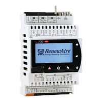
RenewAire HE Series Installation, Operation And Maintenance Manual (152 pages)
PREMIUM COMMERCIAL CONTROLS
Brand: RenewAire
|
Category: Controller
|
Size: 16 MB
Table of Contents
Advertisement
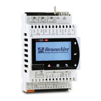
RenewAire HE Series Installation, Operation And Maintenance Manual (104 pages)
ENHANCED COMMERCIAL CONTROLS
Brand: RenewAire
|
Category: Controller
|
Size: 10 MB
Table of Contents
Advertisement

RenewAire HE Series Installation, Operation And Maintenance Manual (32 pages)
Brand: RenewAire
|
Category: Industrial Equipment
|
Size: 3 MB
Table of Contents

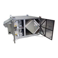
RenewAire HE Series Installation, Operation And Maintenance Manual (28 pages)
Energy Recovery Ventilator
Brand: RenewAire
|
Category: Air Handlers
|
Size: 3 MB
Table of Contents

RenewAire HE Series Installation, Operation And Maintenance Manual (36 pages)
Brand: RenewAire
|
Category: Industrial Equipment
|
Size: 5 MB
Table of Contents


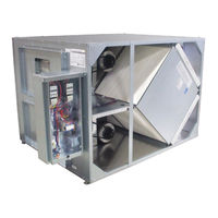
RenewAire HE Series Installation, Operation And Maintenance Manual (28 pages)
ERV
Brand: RenewAire
|
Category: Air Conditioner
|
Size: 3 MB
Table of Contents
RenewAire HE Series Supplemental Installation Manual For Options (8 pages)
Isolation Dampers