Table of Contents
Advertisement
Quick Links
Tel +1 (717) 767-6511
Fax +1 (717) 764-0839
www.redlion.net
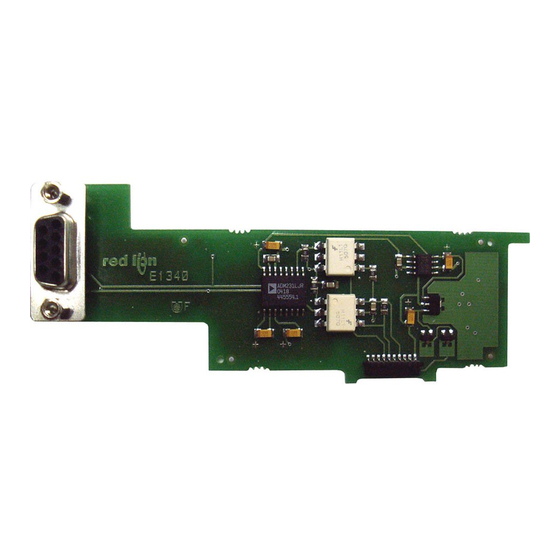
MODEL PAXCDC -SERIAL COMMUNICATIONS PLUG-IN OPTION CARDS
DESCRIPTION
This bulletin serves as a guide for the installation, configuration and
operation of the RS232 and RS485 cards for the PAX family of meters. Only
one communication card can be used at a time.
INSTALLING AN OPTION CARD
Caution: The option and main circuit cards contain static sensitive
components. Before handling the cards, discharge static charges
from your body by touching a grounded bare metal object. Ideally,
handle the cards at a static controlled clean workstation. Also,
handle the cards by the edges only. Dirt, oil or other contaminants
that may contact the cards can adversely affect circuit operation.
Warning: Exposed line voltage exists on the circuit boards. Remove
all power to the meter AND load circuits before accessing the unit.
1. Remove the main assembly from the rear of the case. Squeeze the finger
holds on the rear cover, or use a small screwdriver to depress the side
latches to release it from the case. It is not necessary to separate the rear
cover from the main circuit card.
2. Locate the option card connector for the type of option card to be installed.
Hold the unit by the rear connector, not the display board, when installing
an option card.
3. Install the option card by aligning the option card connector with the slot
bay in the rear cover. The cards are keyed by position with different main
board connector locations. Be sure the connector is fully engaged and the
tab on the option card rests in the alignment slot on the display board.
4. Slide the assembly back into the case. Be sure the rear cover latches fully
into the case.
5. Apply the option card label to the bottom side of the meter. Do not cover
the vents on the top surface of the meter. The surface of the case must be
clean for the label to adhere properly. Apply the label to the area designated
by the large case label.
For Sales and Support, Contact Walker EMD • Toll-free: (800) 876-4444 • Tel: (203) 426-7700 • Fax: (203) 426-7800 • www.walkeremd.com
The PAX meter can be fitted with up to three different option cards. The slot
bays of the option cards are dedicated to a particular card function. The option
card functions are: serial communications, analog output and setpoint output.
Only one card from each function category can be installed into the meter.
TOP VIEW
ORDERING INFORMATION
MODEL
DESCRIPTION
RS485 Serial Communications Output Card with
Terminal Block
Extended RS485 Serial Communications Output
Card with Dual RJ11 Connector
PAXCDC
RS232 Serial Communications Output Card with
Terminal Block
Extended RS232 Serial Communications Output
Card with 9 Pin D Connector
1
Bulletin No. PAXCDC-E
Drawing No. LP0402
Released 3/05
PART NUMBER
PAXCDC10
PAXCDC1C
PAXCDC20
PAXCDC2C
Advertisement
Table of Contents

Related Manuals for red lion PAXCDC


Summary of Contents for red lion PAXCDC
- Page 1 Tel +1 (717) 767-6511 Fax +1 (717) 764-0839 www.redlion.net MODEL PAXCDC -SERIAL COMMUNICATIONS PLUG-IN OPTION CARDS DESCRIPTION This bulletin serves as a guide for the installation, configuration and The PAX meter can be fitted with up to three different option cards. The slot operation of the RS232 and RS485 cards for the PAX family of meters.
-
Page 2: Specifications
SPECIFICATIONS PAXH Isolation For Both Cards: Isolation To Sensor Common: 1400 Vrms for 1 min. Working Voltage: 125 V Isolation To User Input Common: 500 Vrms for 1 min. Working Voltage: 50 V RS485 Communication Card Type: RS485 multi-point balanced interface Isolation To Sensor &... -
Page 3: Parameter Menu
MODULE 7 - S ERIAL OMMUNICATIONS ARAMETERS !"#$% PARAMETER MENU It is necessary to match the PAX meter’s serial communications parameters METER ADDRESS to the host’s parameters before communications can be established. This is " accomplished by using the PAX front panel keys to enter (:,-8 %''- Indicates Program Mode Alternating Display. -
Page 4: Sending Commands And Data
Sending Commands and Data Register Identification Chart Register When sending commands to the meter, a string containing at least one Value Description Applicable Commands/Comments command character must be constructed. A command string consists of a command character, a value identifier, numerical data (if writing data to the Input T, P meter) followed by a the command terminator character * or $. - Page 5 SERIAL COMMANDS FOR PAX SOFTWARE (CSR) Control Status Register Examples: The Control Status Register is used to both directly control the meter’s 1. Set manual mode, turn all setpoints off: outputs (setpoints and analog output), and interrogate the state of the setpoint 7 6 5 4 3 2 1 0:bit location outputs.
-
Page 6: Communication Format
Communication Format Data is transferred from the meter through a serial communication channel. In serial communications, the voltage is switched between a high and low level at a predetermined rate (baud rate) using ASCII encoding. The receiving device reads the voltage levels at the same intervals and then translates the switched levels back to a character. - Page 7 This page intentionally left blank For Sales and Support, Contact Walker EMD • Toll-free: (800) 876-4444 • Tel: (203) 426-7700 • Fax: (203) 426-7800 • www.walkeremd.com...
-
Page 8: Limited Warranty
The Company disclaims all liability for any affirmation, promise or representation with respect to the products. The customer agrees to hold Red Lion Controls harmless from, defend, and indemnify RLC against damages, claims, and expenses arising out of subsequent sales of RLC products or products...