Table of Contents
Advertisement
Advertisement
Table of Contents

Related Manuals for AERMEC WRL Series


Summary of Contents for AERMEC WRL Series
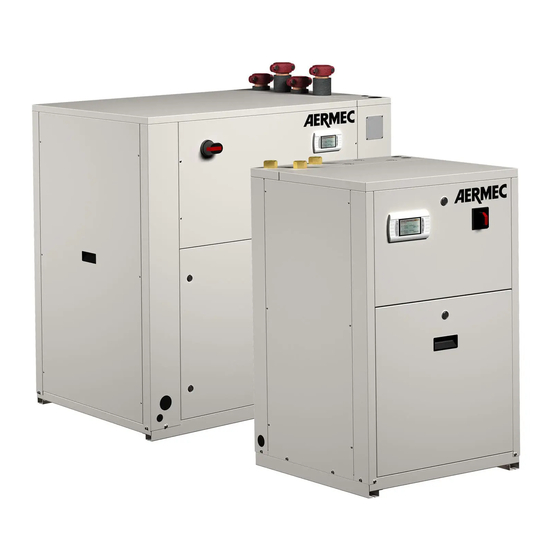
- Page 1 Installati on and Maintenance Manual REVERSIBLE / CHILLER - HEAT PUMPS WATER/WATER 180-650 • HIGH EFFICIENCY • MAXIMUM WATER OUTLET TEMPERATURE 55 °C • DESUPERHEATER • SUITABLE FOR GEOTHERMAL APPLICATIONS BARCODE IWRLI2. 1810. 4900577_05 TRANSLATION FROM ORIGINAL...
- Page 3 Dear Customer, Thank you for choosing an AERMEC product. This product is the result of many years of experience and in-depth engineering research, and it is built using top quality materials and advanced technologies. In addition, the applied mark guarantees that our appliances fully comply with the safety requirements defined by the applicable product’s rules.
-
Page 4: Table Of Contents
INDEX RECEIPT OF THE PRODUCT AND INSTALLATION ........... 6 WRL TABLES ......................7 ANTI-VIBRATION POSITION ..................8 POSITION/DIMENSION CONNECTION WRL ............9 4.1. WRL 180 / 400 (ONLY COOLING) ................9 4.2. WRL 500 / 650 (ONLY COOLING) ................9 4.3. WRLH 180 / 400 (HEAT PUMP) ................10 4.4. WRLH 500 / 650 (HEAT PUMP) ................10 4.5. WRL-E 180-400......................11 4.6. - Page 5 AERMEC S.p.A. 37040 Bevilacqua (VR) Italy – Via Roma, 996 Tel. (+39) 0442 633111 – Fax (+39) 0442 93577 www.aermec.com DICHIARAZIONE DI CONFORMITÀ CE / EC DECLARATION OF CONFORMITY / DECLARATION DE CONFORMITE CE KONFORMITÄTSERKLÄRUNG EG / DECLARACIÓN DE CONFORMIDAD CE...
-
Page 6: Receipt Of The Product And Installation
FOR THE INSTALLER RECEIPT OF THE ► HANDLING PRODUCT AND INSTALLATION 1.0.1. Receipt and handling The machine is sent from the factory wrapped with estincoil placed on a loading pallet Before handling the unit, verify the lifting capacity of the machines used. Handling must be performed by qualified, suitably equipped staff. -
Page 7: Wrl Tables
WRL TABLES ►DIMENSIONS WRL 180 / 400 (mm) 1320 1320 ► DIMENSIONS WRL / WRLH - 500-650 (mm) 2009 2060 ► WEIGHT WRL (Kg) empty weight weight with pallet running weight WRLH (Kg) empty weight weight with pallet running weight IWRLI2. -
Page 8: Anti-Vibration Position
ANTI-VIBRATION POSITION ► WRL 180 / 400 - WRL-H 180/400 1170 1170 ► WRL 500 / 650 - WRL-H 500 / 650 1899 1899 IWRLI2. 1810. 4900577_05... -
Page 9: Position/Dimension Connection Wrl
POSITION/DIMENSION CONNECTION WRL 4.1. ► WRL (ONLY COOLING 180 / 400 Units in “mm”. EVAPORATOR CONDENSER DESUPERHEATER Electrical alimentation ► CONNECTIONS (Ø) Evaporator 2” 2” 2” 2” 2” 2” 2” 2” Condenser 2” 2” 2” 2” 2” 2” 2” 2” Desuperheater 1”½... -
Page 10: Wrlh 180 / 400 (Heat Pump)
4.3. ► WRLH (HEAT PUMP 180 / 400 Units in “mm”. GEOTHERMAL SIDE SYSTEM SIDE DESUPERHEATER Electrical alimentation ► CONNECTIONS (Ø) Geothermal side 2” 2” 2” 2” 2” 2” 2” 2” System side 2” 2” 2” 2” 2” 2” 2” 2”... -
Page 11: Wrl-E 180-400
4.5. WRL-E 180-400 EVAPORATOR 2” grooved joints LINE OF LIQUID - D.22 LINE OF GAS - D.22 4.6. WRL-E 500-650 EVAPORATOR 2”½ grooved joints LINE OF LIQUID - D.28 LINE OF GAS - D.35 IWRLI2. 1810. 4900577_05... -
Page 12: Barycentre
BARYCENTRE WRL 500 / 650 WRL 180 / 400 Total weight Support A Support B Support C Support D (machine [kg] [kg] [kg] [kg] working) 109.5 116.4 83.4 88.7 109.5 116.4 83.4 88.7 111.7 116.7 86.7 90.6 113.5 120.5 86.6 91.9 1005 140.5... -
Page 13: Electric Connections
ELECTRIC CONNECTIONS All the electrical operations must be carried out bySTAFF IN POSSESSION OF THE NECESSARY QUALIFICATIONS BY LAW, suitably trained and informed on The WRL heat pumps are completely the risks related to these operations. wired at the factory and only require connection to the electrical mains, downstream from a unit switch, The characteristics of the electrical lines and of the related components... -
Page 14: Recommended Electric Cable Section
Prior to ATTENTION: the work to be carried out by the AERMEC Check the tightening of all power wire service personnel, all other works (electrical clamps on commissioning and after and hydraulic hook-ups, priming and 30 days from start-up. -
Page 15: Season Changeover
7.3. SEASON CHANGEOVER - For every season change, check that the functioning limits lie within the limits. - Check that the compressor input current is lower than the maximum On-Off/ Mode indicated in the technical data table. Heat Pump Unit - Check, that in models with three- phase power supply, that the compressor noise level is not... -
Page 16: Wiring Diagram
WIRING DIAGRAM µPC J1 - power supply +Vdc J2 - probe supply +5 Vref J3 - analog input +Vdc J12 - J4 - digital input J13 - DIC1 J5 - analog output J14 - J18 - analog input J17 - valve 2 J16 - digital input ID10 IDC2... -
Page 17: Modbus Electrical Connection
MODBUS ELECTRICAL CONNECTION STA/H Through the door named “Field Bus” application, WRL is able to monitor several Modbus slave. Remember to add at the end of a line resistance of 120 ohms between Tx + and Tx-. FIELD BUS RX-/TX- RX-/TX- RX+/TX+ RX+/TX+... -
Page 18: Maintenance
MAINTENANCE MAINTENANCE ATTENTION Any cleaning, inspection, control, routine and extraordinary maintenance must be performed by experienced, authorised personnel and qualified to perform the above tasks. These tasks must be performed to perfection as prescribed by M.D. 37/2008. During the execution of - Risks of electric discharges; Risk of injuries due to the presence of rotating parts;... - Page 19 Place a sign reading ‘’Do not turn on – maintenance in progress’’ on the open isolator; Equip yourself with tools in good condition and make sure to have fully understood the instructions before using them; Equip yourself with the appropriate personal protective equipment as indicated in paragraph 1 of this report; For outdoor units, do not perform interventions in dangerous weather conditions such as rain, snow, fog, thunderstorms, etc; The cooling circuit components must be replaced after draining the refrigerant gas contained in the circuit; During venting protect yourself against any leakage of fluids at dangerous temperatures and/or pressures; Always use appropriate equipment (extractor, antistatic bracelet etc) when replacing electronic boards; If replacing a motor, compressor, evaporator, condensing coil or any other heavy element, make sure that the lifting devices are compatible with the weight to be handled; In air units with independent compressor compartment, do not access the fan compartment without having first disconnected the machine through the isolator on the board and having placed a sign reading ‘’Do not turn on – maintenance in progress’’; Always and only use original spare parts purchased directly from Aermec or from official dealers. Contact Aermec should it be necessary to move the unit one year after its positioning on-site or it must be dismantled; It is not permitted to change the refrigerant, hydraulic or electric layout of the unit, or its control logic unless expressly authorised by Aermec; The machine must be loaded with the refrigerant in the feature label and in the required quantity; Make sure to have removed all tools, electrical cables or other loose object and having perfectly connected the machine to the system before closing it and starting it; The inspections and measurements necessary to establish the correct functioning of the machine to be run with the machine in operation, must be per- formed with the machine closed (framework fixed on the machine), reading the measurements collected by the control board and viewable in the control panel of the same. In the case of machines with cooling circuit compartment open, stand in front of the control panel of the electrical panel remaining distant and not exposed to the under pressure parts of the cooling circuit ATTENTION When having to take measurements with the machine on and the electrical panel and cooling circuit open, be careful since the machine is live, the cooling circuit contains high pressure gas, the pipes may be hot or cold, some parts may be in motion.
- Page 20 The measurements of the compressor inlet and outlet temperature and pressure to determine the overheating and subcooling of the machine, must be carried out as follows: With machine off, access its cooling circuit; Connect the necessary instruments, • Pressure gauges connected through appropriate extensions to the compressor inlet and outlet pressure plugs; • Thermometers connected to thermocouple probes that are fixed to the compressor inlet and outlet pipes. Avoid using metratast that require the opera- tor to near the machine cooling circuit; - Access the machines and acquire the measurements, keeping AWAY from the under pressure parts of the cooling circuit; - As soon as the measurements are taken, turn off the machine, remove the instruments and close the cooling circuit compartment. The high/low pressure switch, where present must be tested with the machine “closed”, reading the high pressure circuit pressure on the machine control panel. In case of machines with the cooling circuit compartment not closed by framework, the high/low pressure switch must be tested by standing in front of the machine panel where the control panel is located, remaining distant and not exposed to the under pressure parts of the cooling circuit. Warning; Warning; Warning; Warning; Warning; Warning; Hot surface Electricity Flammable material Sharp element Biological hazard Wear head...
-
Page 21: Maintenance - List Of The Recommended Periodic Interventions
MAINTENANCE - LIST OF THE RECOMMENDED PERIODIC INTERVENTIONS MAINTENANCE - LIST OF THE RECOMMENDED PERIODIC INTERVENTIONS MAINTENANCE - LIST OF THE RECOMMENDED PERIODIC INTERVENTIONS RECOMMENDED PERIODIC MAINTENANCE INTERVENTIONS FREQUENCY RECOMMENDED PERIODIC MAINTENANCE INTERVENTIONS DESCRIPTION functi oning hours months months months FREQUENCY months DESCRIPTION... - Page 22 MAINTENANCE - LIST OF THE RECOMMENDED PERIODIC INTERVENTIONS RECOMMENDED PERIODIC MAINTENANCE INTERVENTIONS TO UNITS WITH CENTRIFUGAL COMPRESSORS FREQUENCY DESCRIPTION 6 months 12 months other GENERAL CHECKS Check that the compressor is not damaged • Check that there are no excessive vibrati ons induced by other operati ng components • CHECKS ON ELECTRICAL PARTS Check the power supply voltage • Check the proper fastening of the compressor power supply cables •...
- Page 23 This marking indicates that this product should not be disposed with other household wastes throughout the EU. To prevent possible harm to the environment or human health from uncontrolled disposal of Waste Electrical and Electronic Equipment (WEEE), please return the device using appropriate collection systems, or contact the retailer where the product was purchased. Please contact your local authority for further details.
- Page 24 Via Roma, 996 37040 Bevilacqua (VR) - Italia Tel. + 39 0442 633111 Fax +39 0442 93577 marketing@aermec.com www.aermec.com Aermec reserves the right to make all modification deemed necessary for improving the product at any time with any modification of technical data.
Need help?
Do you have a question about the WRL Series and is the answer not in the manual?
Questions and answers