Table of Contents
Advertisement
REVERSIBLE HEAT PUMP -
WATER/WATER HEAT PUMP
•
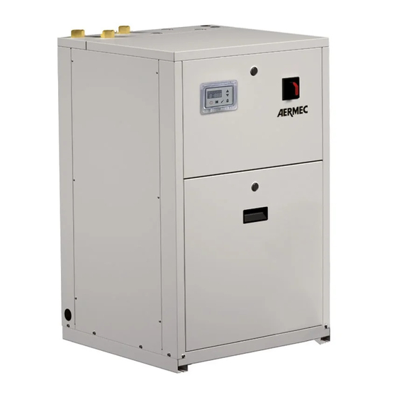
INDOOR UNIT
•
HIGH EFFICIENCIES
•
PRODUCTION OF HOT WATER UP TO 60°
•
USED FOR GEOTHERMAL APPLICATIONS
•
REVERSIBLE GAS SIDE
Aermec
participate in the EUROVENT
program: LCP/W/P/C.
the products are present on the site
www .eurovent-certification. com
Technical Manual
WRL-H
025/160
GB
IWRLTY. 1201. 5890974_06
Advertisement
Table of Contents

Related Manuals for AERMEC WRL-H


Summary of Contents for AERMEC WRL-H
- Page 1 REVERSIBLE HEAT PUMP - Technical Manual WRL-H WATER/WATER HEAT PUMP • INDOOR UNIT • HIGH EFFICIENCIES 025/160 • PRODUCTION OF HOT WATER UP TO 60° • USED FOR GEOTHERMAL APPLICATIONS • REVERSIBLE GAS SIDE Aermec participate in the EUROVENT program: LCP/W/P/C.
- Page 3 AERMEC S.p.A AERMEC S.p.A. reserves the right to make any modifications considered necessary to improve its products at any moment and is not obliged to add these modifications to machines that have already been fabricated, delivered or are under construction.
-
Page 4: Table Of Contents
Calibration of control and safety parameters ..47 Selection and place of installation ......48 16.1. Barycentres ..............48 Anti-legionella function ..........49 Refrigerant circuits ............ 50 18.1. WRL-H 025-080 ............50 18.2. WRL-H 100 - 160 ............51 IWRLTY. 1201. 5890974_06... - Page 5 AERMEC S.p.A 37040 Bevilacqua (VR) Italy–Via Roma, 996 Tel. (+39) 0442 633111 Telefax 0442 93730–(+39) 0442 93566 www .aermec. com - info @ aermec. com WRL-H SERIAL NUMBER DECLARATION OF CONFORMITY We, the undersigned, hereby declare under our own responsibility that the assembly...
-
Page 6: General Warnings
PRODUCT IDENTIFICATION The WRL-H heat pumps can be identified by: − PACKING LABEL which shows the product identification data − TECHNICAL PLATE (see position chap. -
Page 7: Presentation
1. GEOTHERMIC SYSTEMS cooled and operate with R410A Silent Production of water for heating refrigerant. The WRL-H units are distinguished for its systems for systems with FAN working silence. COILS, RADIANT PANELS OR LOW They are INDOOR UNITS with hermetic... - Page 8 CONFIGURATOR 1,2,3 4,5,6 ° ° ° ° ° FIELD CODE 1, 2, 3 025 - 030 - 040 - 050 - 070 - 080 - 100 - 140 - 160 4, 5, 6 SIZES FIELD OF USE Electronic thermostatic valve with water produced up to 8 °C (AS PER STANDARD FOR ALL MODELS) MODEL: Heat Pump VERSION:...
-
Page 9: Description Of Components
In case of power failure control. 6.3. MAIN OPERATIONS the valve remains locked "Chiller" water set-point compensation due The WRL-H heat pumps are supplied as per in the working position. In standard with: to external temp. order to avoid unnecessary •... - Page 10 system return Set Point is established seconds after the compressor is switched in accordance with the external air off. temperature. Function guaranteed if the external air probe is present (ACCESSORY). Anti-freeze alarm The anti-freeze function is only active if Electronic controller μPC the unit is ON or in stand-by.
-
Page 11: Accessories
ON-OFF valve or a zone pump probe with plastic container. and the dehumidifier. − VMFCRP: Zones Management; − SSM: Probe to be used together with the 7.1. ACCESSORIES COMPATIBILITY TABLE WRL-H AER485P1 ● ● ● ● ● ●... - Page 12 HEATING POWER WRL-H VERSION U.M. 025H 030H 040H 050H 070H 080H 100H 140H 160H SUPPLY HEATING MODE 10/* - 30/35 °C “RADIANT PANELS” EN14511 230V-1 8.13 10.16 13.02 Heating capacity ° 400V-3N 8.06 10.16 12.95 17.09 22.52 25.98 34.23 45.12 51.94...
- Page 13 HEATING POWER WRL-H VERSION U.M. 025H 030H 040H 050H 070H 080H 100H 140H 160H SUPPLY HEATING MODE 0/-3 - 30/35 °C “FROST” 230V-1 6.28 8.44 10.17 Heating capacity ° 400V-3N 6.23 7.90 10.11 13.26 17.29 20.51 26.52 34.58 41.16 230V-1 1.56...
- Page 14 HEATING POWER WRL-H VERSION U.M. 025H 030H 040H 050H 070H 080H 100H 140H 160H SUPPLY HEATING MODE 10/* - 40/45 °C “FAN COILS” EN14511 230V-1 7.90 9.98 12.64 Heating capacity ° 400V-3N 7.90 9.51 12.42 16.43 20.91 24.12 32.90 41.90 48.20...
- Page 15 HEATING POWER WRL-H VERSION PUMPS U.M. 025H 030H 040H 050H 070H 080H 100H 140H 160H SUPPLY COOLING MODE 10/5 - 40/45 °C “FAN COILS” 230V-1 7.60 9.68 12.16 Heating capacity ° 400V-3N 7.58 9.17 11.93 15.81 20.04 23.17 31.62 40.08 46.20...
- Page 16 COOLING POWER WRL-H VERSION PUMPS U.M. 025H 030H 040H 050H 070H 080H 100H 140H 160H SUPPLY COOLING MODE 12/7 - 30/35 °C “FAN COILS” 230V-1 6.31 7.92 10.32 Cooling capacity ° 400V-3N 6.31 8.14 10.43 13.79 17.76 20.28 27.57 35.46 40.51...
- Page 17 Weight Minimum content of water in case of process applications, or operating with low load. Sound power; Aermec determines the sound power value on the basis of measurements taken in accordance with standard 9614-2, in compliance with the Eurovent certification.
-
Page 18: Operating Limits
OPERATING LIMITS FUNCTIONING LIMITS The operating limits diagram is relative to a ∆t on the evaporator and the condenser of 5°C. Condenser outlet inlet difference (Δtc): 48°C min: 5° C. max: 22° C. Functioning Functioning Standard functioning / X Standard functioning / X Evaporator outlet inlet difference (Δte): with glycol X / Y with glycol X / Y... -
Page 19: Design Data
8.1. DESIGN DATA High pressure Low pressure REFRIGERANT SIDE side side Acceptable maximum pressure Acceptable maximum temperature °C Acceptable minimum temperature °C IWRLTY. 1201. 5890974_06... -
Page 20: Performance And Absorption That Differ From The Nominal - Standard Versions
WRL025XH°°°°°°M PERFORMANCE IN HEATING | COOLING MODE PERFORMANCE AND ABSORPTION THAT DIFFER FROM THE NOMINAL - STANDARD VERSIONS. 9.1. WRL025XH°°°°°°°M HEATING MODE Condenser water outlet temperature °C C.O.P. C.O.P. C.O.P. C.O.P. C.O.P. C.O.P. C.O.P. C.O.P. [kW] [kW] [kW] [kW] [kW] [kW] [kW] [kW]... - Page 21 WRL030XH°°°°°°M PERFORMANCE IN HEATING | COOLING MODE 9.3. WRL030XH°°°°°°°M HEATING MODE Condenser water outlet temperature °C C.O.P. C.O.P. C.O.P. C.O.P. C.O.P. C.O.P. C.O.P. C.O.P. [kW] [kW] [kW] [kW] [kW] [kW] [kW] [kW] 7.73 1.63 4.75 7.66 1.81 4.22 7.61 2.05 3.71 7.54 2.34...
- Page 22 WRL040XH°°°°°°M PERFORMANCE IN HEATING | COOLING MODE 9.5. WRL040XH°°°°°°M HEATING MODE Condenser water outlet temperature °C C.O.P. C.O.P. C.O.P. C.O.P. C.O.P. C.O.P. C.O.P. C.O.P. [kW] [kW] [kW] [kW] [kW] [kW] [kW] [kW] 9.13 1.82 5.03 8.95 2.09 4.28 8.82 2.36 3.73 8.73 2.66...
- Page 23 WRL025XH°°°°°°° PERFORMANCE IN HEATING | COOLING MODE 9.7. WRL025XH°°°°°°° HEATING MODE Condenser water outlet temperature °C C.O.P. C.O.P. C.O.P. C.O.P. C.O.P. C.O.P. C.O.P. C.O.P. [kW] [kW] [kW] [kW] [kW] [kW] [kW] [kW] 5.61 1.24 4.51 5.46 1.42 3.84 5.35 1.60 3.34 5.28 1.81...
- Page 24 WRL030XH°°°°°°° PERFORMANCE IN HEATING | COOLING MODE 9.9. WRL030XH°°°°°°° HEATING MODE Condenser water outlet temperature °C C.O.P. C.O.P. C.O.P. C.O.P. C.O.P. C.O.P. C.O.P. C.O.P. [kW] [kW] [kW] [kW] [kW] [kW] [kW] [kW] 7.30 1.46 5.01 7.08 1.66 4.26 6.87 1.88 3.66 6.68 2.12...
- Page 25 WRL040XH°°°°°°° PERFORMANCE IN HEATING | COOLING MODE 9.11. WRL040XH°°°°°°° HEATING MODE Condenser water outlet temperature °C C.O.P. C.O.P. C.O.P. C.O.P. C.O.P. C.O.P. C.O.P. C.O.P. [kW] [kW] [kW] [kW] [kW] [kW] [kW] [kW] 9.16 1.87 4.89 8.96 2.11 4.25 8.76 2.36 3.71 8.56 2.64...
- Page 26 WRL050XH°°°°°°° PERFORMANCE IN HEATING | COOLING MODE 9.13. WRL050XH°°°°°°° HEATING MODE Condenser water outlet temperature °C C.O.P. C.O.P. C.O.P. C.O.P. C.O.P. C.O.P. C.O.P. C.O.P. [kW] [kW] [kW] [kW] [kW] [kW] [kW] [kW] -8 12.22 2.40 5.09 11.79 2.71 4.35 11.48 3.05 3.76 11.27 3.44 3.28 11.15 3.89 2.87...
- Page 27 WRL070XH°°°°°°° PERFORMANCE IN HEATING | COOLING MODE 9.15. WRL070XH°°°°°°° HEATING MODE Condenser water outlet temperature °C C.O.P. C.O.P. C.O.P. C.O.P. C.O.P. C.O.P. C.O.P. C.O.P. [kW] [kW] [kW] [kW] [kW] [kW] [kW] [kW] -8 15.22 3.27 4.66 15.23 3.55 4.29 14.93 3.93 3.80 14.47 4.41 3.28 13.99 4.98 2.81...
- Page 28 WRL080XH°°°°°°° PERFORMANCE IN HEATING | COOLING MODE 9.17. WRL080XH°°°°°°° HEATING MODE Condenser water outlet temperature °C C.O.P. C.O.P. C.O.P. C.O.P. C.O.P. C.O.P. C.O.P. C.O.P. [kW] [kW] [kW] [kW] [kW] [kW] [kW] [kW] -8 18.28 4.04 4.52 18.34 4.32 4.25 17.99 4.71 3.82 17.35 5.22 3.32 16.53 5.87 2.82...
- Page 29 WRL100°H°°°°°°° PERFORMANCE IN HEATING | COOLING MODE 9.19. WRL100°H°°°°°°°° HEATING MODE Condenser water outlet temperature °C C.O.P. C.O.P. C.O.P. C.O.P. C.O.P. C.O.P. C.O.P. C.O.P. [kW] [kW] [kW] [kW] [kW] [kW] [kW] [kW] -8 24.45 4.81 5.08 23.58 5.42 4.35 22.96 6.11 3.76 22.54 6.89 3.27 22.29 7.79 2.86...
- Page 30 WRL140°H°°°°°°° PERFORMANCE IN HEATING | COOLING MODE 9.21. WRL140°H°°°°°°° HEATING MODE Condenser water outlet temperature °C C.O.P. C.O.P. C.O.P. C.O.P. C.O.P. C.O.P. C.O.P. C.O.P. [kW] [kW] [kW] [kW] [kW] [kW] [kW] [kW] -8 30.45 6.51 4.67 30.46 7.06 4.31 29.86 7.83 3.81 28.94 8.79 3.29 27.98 9.91 2.82...
- Page 31 WRL160°H°°°°°°° PERFORMANCE IN HEATING | COOLING MODE 9.23. WRL160°H°°°°°°° HEATING MODE Condenser water outlet temperature °C C.O.P. C.O.P. C.O.P. C.O.P. C.O.P. C.O.P. C.O.P. C.O.P. [kW] [kW] [kW] [kW] [kW] [kW] [kW] [kW] -8 36.07 8.09 4.46 36.82 8.64 4.26 36.80 9.42 3.90 35.68 10.45 3.41 33.15 11.74 2.82 -6 38.45 8.11 4.74 38.89 8.66...
-
Page 32: Pressure Drops
PRESSURE DROPS FUNCTIONING IN HEATING MODE CONDENSER 1000 2000 3000 4000 5000 6000 7000 8000 9000 10000 11000 12000 Water flow rate (l/h) EVAPORATOR 1000 2000 3000 4000 5000 6000 7000 8000 9000 10000 11000 12000 13000 14000 15000 16000 Water flow rate (l/h) The tables state the correction to apply to the pressure drops on variation of the... - Page 33 COOLING MODE FUNCTIONING CONDENSER/TOTAL RECOVERY 1000 2000 3000 4000 5000 6000 7000 8000 9000 10000 11000 12000 Water flow rate (l/h) EVAPORATOR 1000 2000 3000 4000 5000 6000 7000 8000 9000 10000 11000 12000 13000 14000 15000 16000 17000 Water flow rate (l/h) The tables state the correction to apply to the pressure drops on variation of the average temperature.
- Page 34 VERSION WITH STORAGE TANK “A” FUNCTIONING IN HEATING MODE CONDENSER Water flow rate (l/h) COOLING MODE FUNCTIONING EVAPORATOR Water flow rate (l/h) The tables state the correction to apply = “field of application minimum flow rates to the pressure drops on variation of the not accepted with standard have been calculated with average temperature.
- Page 35 WRL025°H°T°°°°M TOTAL RECOVERY PERFORMANCE WRL030°H°T°°°°M 10.1. WRL025°H°T°°°°M TOTAL RECOVERY OUTPUT WATER TEMPERATURE °C [kW] [kW] [kW] [kW] [kW] [kW] [kW] [kW] 5.49 1.41 5.43 1.59 5.42 1.80 5.43 2.03 5.48 2.30 5.87 1.39 5.80 1.57 5.76 1.78 5.75 2.02 5.77 2.29 6.26 1.37...
- Page 36 WRL040°H°T°°°°M TOTAL RECOVERY PERFORMANCE WRL025°H°T°°°°° 10.3. WRL040°H°T°°°°M TOTAL RECOVERY OUTPUT WATER TEMPERATURE °C [kW] [kW] [kW] [kW] [kW] [kW] [kW] [kW] 8.87 2.02 8.68 2.27 8.57 2.55 8.52 2.88 8.51 3.25 9.51 2.00 9.28 2.25 9.13 2.54 9.03 2.87 8.97 3.25 10.15 1.98...
- Page 37 WRL030°H°T°°°°° TOTAL RECOVERY PERFORMANCE WRL040°H°T°°°°° 10.5. WRL030°H°T°°°°° TOTAL RECOVERY OUTPUT WATER TEMPERATURE °C [kW] [kW] [kW] [kW] [kW] [kW] [kW] [kW] 6.56 1.45 6.58 1.66 6.64 1.91 6.72 2.20 6.78 2.51 7.11 1.43 7.10 1.65 7.12 1.90 7.15 2.19 7.17 2.51 7.63 1.42...
- Page 38 WRL050°H°T°°°°° TOTAL RECOVERY PERFORMANCE WRL070°H°T°°°°° 10.7. WRL050°H°T°°°°° TOTAL RECOVERY OUTPUT WATER TEMPERATURE °C [kW] [kW] [kW] [kW] [kW] [kW] [kW] [kW] 11.85 2.56 11.61 2.90 11.47 3.25 11.40 3.62 11.37 4.05 12.68 2.53 12.39 2.87 12.20 3.22 12.07 3.60 11.98 4.03 13.50 2.50...
- Page 39 WRL080°H°T°°°°° TOTAL RECOVERY PERFORMANCE WRL100°H°T°°°°° 10.9. WRL080°H°T°°°°° TOTAL RECOVERY OUTPUT WATER TEMPERATURE °C [kW] [kW] [kW] [kW] [kW] [kW] [kW] [kW] 15.81 4.00 16.39 4.37 16.24 4.79 15.22 5.26 13.17 5.78 16.86 4.00 17.39 4.38 17.31 4.81 16.49 5.30 14.77 5.85 18.05 4.00...
- Page 40 WRL140°H°T°°°°° TOTAL RECOVERY PERFORMANCE WRL160°H°T°°°°° 10.11. WRL140°H°T°°°°° TOTAL RECOVERY OUTPUT WATER TEMPERATURE °C [kW] [kW] [kW] [kW] [kW] [kW] [kW] [kW] 27.15 6.85 26.77 7.47 26.39 8.17 26.05 8.95 25.81 9.83 29.75 6.85 29.23 7.48 28.71 8.21 28.23 9.04 27.84 9.96 32.35 6.84...
-
Page 41: Ethylene Glycol Solutions
ETHYLENE GLYCOL SOLUTIONS − The corrective factors of cooling FcGDpF (a) 2.20 FcGDpF (b) capacity and input power take into 2. 1 0 2.00 account the presence of glycol FcGDpF (c) 1.90 and the difference in evaporation FcGDpF (d) 1.80 temperatures. -
Page 42: Useful Static Pressures
USEFUL STATIC PRESSURES FUNCTIONING IN HEATING MODE CONDENSER USEFUL STATIC PRESSURES Water flow rates (l/h) EVAPORATOR USEFUL STATIC PRESSURES Water flow rates (l/h) If work points are selected outside of the static pressure curves range, contact the head office. IWRLTY. 1201. 5890974_06... - Page 43 COOLING MODE FUNCTIONING CONDENSER USEFUL STATIC PRESSURES Water flow rates (l/h) EVAPORATOR USEFUL STATIC PRESSURES Water flow rates (l/h) TOTAL RECOVERY USEFUL STATIC PRESSURES Water flow rates (l/h) IWRLTY. 1201. 5890974_06...
- Page 44 VERSION WITH INVERTER PUMP “I” COOLING MODE FUNCTIONING CONDENSER USEFUL STATIC PRESSURES WITH INVERTER PUMP Water flow rates (l/h) FUNCTIONING IN HEATING MODE EVAPORATOR USEFUL STATIC PRESSURES WITH INVERTER PUMP Water flow rates (l/h) If work points are selected outside of the static pressure curves range, contact the head office.
- Page 45 VERSION WITH STORAGE TANK “A” FUNCTIONING IN HEATING MODE STORAGE TANK USEFUL STATIC PRESSURES WITH INVERTER PUMP 1000 2000 3000 4000 5000 6000 7000 8000 9000 10000 11000 12000 13000 14000 15000 16000 17000 Water flow rates (l/h) COOLING MODE FUNCTIONING EVAPORATOR USEFUL STATIC PRESSURES WITH INVERTER PUMP 1000 2000 3000...
-
Page 46: Expansion Vessel Calibration
Water inlet temperature ....40 °C Water outlet temperature ..45 °C Sound power; Aermec determines the sound power value on the basis of measurements taken in accordance with standard 9614-2, in com- pliance with the Eurovent certification. Sound pressure in an unrestricted range on a reflective plane (directional fact. Q=2), 1m away from the unit external surface, complying with ISO 3744. -
Page 47: Calibration Of Control And Safety Parameters
CALIBRATION OF CONTROL AND SAFETY PARAMETERS CONTROL PARAMETERS 6°C Cooling Set Inlet water temperature in cooling functioning mode. 20°C DEFAULT 7°C 20°C Heating Set Inlet water temperature in heating functioning mode. 55°C DEFAULT 40°C -99°C Anti-freeze Intervention temperature of the anti-freeze alarm on the EV side (water 99°C intervention outlet temperature). -
Page 48: Selection And Place Of Installation
SELECTION AND PLACE OF INSTALLATION The WRL-H heat pump is set-up for an with national laws in the country of INTERNAL application. destination. It is shipped pre-tested and only requires − It is mandatory to foresee to the the electrical and hydraulic connections. -
Page 49: Anti-Legionella Function
ANTI-LEGIONELLA FUNCTION The ANTI-LEGIONELLA function is DHW reaches a maximum of 65°C for ATTENTION: designed to eliminate legionella germs at least 5 minutes and a maximum of Changing parameters that that can reside in the DHW tanks. This 120 minutes, every Sunday at 3.00 a.m. identifi... - Page 50 MAIN COOLING LAYOUT 18.1. WRL-H STANDARD 025 / 080 Condenser Compressor Evaporator Dehydrator filter High pressure switch High pressure transducer Indicator for liquid passage Low pressure transducer Electronic thermostati c valve Cycle reversing valve 18.2. WRL-H STANDARD 100 / 160...
- Page 51 18.3. WRL-HT 025 / 080 Condenser Compressor Evaporator Dehydrator filter High pressure switch High pressure transducer Indicator for liquid passage Low pressure transducer Total recovery (opti onal version) Electronic thermostati c valve Cycle reversing valve 18.4. WRL-HT 100 / 160 Condenser Compressor Evaporator...
- Page 52 Telefax (+39) 0442 93730 - (+39) 0442 93566 The technical data given on the following documentation is www .aermec. com not binding. Aermec reserves the right to apply at any time all the modifications deemed necessary for improving the product.
Need help?
Do you have a question about the WRL-H and is the answer not in the manual?
Questions and answers