Advertisement
Quick Links
Advertisement

Related Manuals for AERMEC HRS-HRS W


Summary of Contents for AERMEC HRS-HRS W
- Page 1 HRS-HRS W HEAT RECOVERY UNIT Installation, Use and Maintenance Manual 4530600_00 dated 0904...
- Page 2 This instruction book is an integral part of the appliance and as a consequence must be kept carefully and must ALWAYS accompany the appliance even if transferred to other owners or users or transferred to another plant. If damaged or lost, request another copy from the Manufacturer.
- Page 3 SYMBOLS WARNING DANGER DANGER RISK F ELECTRIC SHOCK ATTENTION ONLY AUTHORISED STAFF PROHIBITION Important Note The heat recovery unit is a machine designed and built exclusively to change air in the civil environments, incompatible with toxic and inflammable gases. Therefore it cannot be used in those environments where the air is mixed and/or altered by other gaseous composites and/or solid particles.
- Page 4 INDEX SECTION 1 - GENERAL FEATURES 1.1 Manual presentation page 5 1.2 Construction features page 5 1.3 Orientations possible for HRS range horizontal models page 6 1.4 HRS range unit technical data page 7 1.5 HRS - HRSW range unit technical data page 8 1.6 Accessories available page 8...
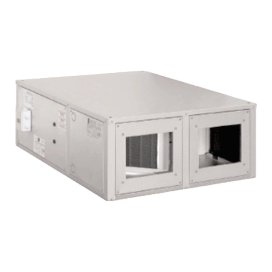
- Page 5 INTRODUCTION The heat recovery units for horizontal installation are characterised by small dimensions and easy assembly. The heat recovery units allow to join maximum environmental comfort with sure energy saving. Forced ventilation must be created in current air conditioning and treatment plants, which leads to the expulsion of treated air, determining large energy consumption and increase in costs.
- Page 6 1.3 HRS possible orientations and clearance • STANDARD ORIENTATION TYPE 03 Depending on the configuration of the network and the space available, it is possible to choose the other 3 orientations AT THE TIME OF PLACING THE ORDER, (TYPE 01 - 02 - 04). ORIENTAMENTO TIPO 02 / Configuration type 02 ORIENTAMENTO TIPO 01 / CONFIGURATION TYPE 01 Aria espulsa / Exhaust air...
- Page 7 MODEL HRS 090 HRS 160 HRS 190 HRS 230 HRS 300 HRS 390 HRS 030 HRS 060 HRS 090W HRS160W HRS190W HRS 230W HRS 300W HRS 390W Size 1140 1300 1380 1650 1650 1750 1230 1230 1230 Ø gaz Ø Øi Weight Orientamento 1 e 2 / Configuration 1 and 2...
- Page 8 It is possible to intake or expel the air frontally and laterally by simply changing the position of the panels, as illustrated at the side. This can simplify the realisation of the air ducts greatly, bringing an effective saving to installation times.
- Page 9 HRS_W UNIT WITH WATER POST-HEATING SECTION The use of the coil is requested when post-heating is necessary and must be fixed directly inside the heat recovery unit. BATTERIA POST-RISCALDAMENTO WATER HEATING COIL - BCR Resa termica / Heating capacity 12.2 14.4 20.3 24.2...
- Page 10 HRS – CS TECHNICAL DATA HRS with HRS_CS Geometry 25x22 25x22 25x22 25x22 25x22 25x22 Pipes for row n° Rows n° Louver pitch Heating HRS090 HRS160 HRS190 HRS230 HRS300 HRS390 Heating capacity 19,65 23,7 30,5 46,2 Air outlet temperature °C 43,4 46,5 43,7...
- Page 11 SECTION 2 - TRANSPORT SECTION 3 - INSTALLATION AND START-UP page 11 Manuel d'Installation et de Maintenance des Récupérateurs de Chaleur...
- Page 12 3.2 Preliminary operations • Check the perfect integrity of the various components of the unit. • Check that the packaging contains the accessories for installation and the documentation. • Transport the packaged section as near as possible to the place of installation. •...
- Page 13 3.5 Connection to the ducts IMPORTANT: IT IS PROHIBITED TO START THE HRS UNIT IF THE FAN VENTSARE NOT DUCTED OR PROTECTED WITHACCIDENT-PREVENTION MESHACCORDING TO UNI 9219 STANDARDAND SUCCESSIVEAMENDMENTS • The ducts must be dimensioned depending on the plant and the aeraulic features of the unit fans. An incorrect calculation of the ducting causes a loss of power or the intervention of any devices present on the plant.
- Page 14 3.7 iany installation of the section with water coil HrS_CS Attention: the installation of the section with water coil leads to additional pressure drops in the introduction circuit. These drops are stated in the table on page 9 (“Coil air side pressure drop”) A plastic bag is also supplied with the section with water coil.
- Page 15 3.8 Hydraulic connection of the section with water coil HrS_CS • The installation and connection operations of the pipes are operations that can compromise the good functio- ning of the plant or worse, cause irreversible damage to the machine. These operations must only be performed by specialised staff.
- Page 16 4.1 Electronic speed adjuster HRS_SC (mod. 30 - 60) The speed adjuster is suitable for wall installation and allows the adjustment of the fan with one-speed single-phase motor. Two adjuster models are envisioned according to the fan motor input current: HRS 030SC and HRS060SC. The following are present on the front of the contropanel: •...
-
Page 17: Wiring Diagrams
4.2 Wiring diagrams HRS 030 – 060 DIRECT WIRING DIAGRAM FACTORY CONNECTIONS A tratteggio sono evidenziati i collegamenti da effettuarsi a cura dell’installatore. / Dashed lines show the connections to be carried out by the installer. Tutte le linee devono essere protette all’origine a cura dell’installatore. / All lines must be protected at the origin by the installer. HRS 030 –... - Page 18 HRS090 - 160 - 190 DIRECT WIRING DIAGRAM Nello schema è indicato il fun- zionamento alla massima FACTORY CONNECTIONS velocità.Per il funzionamento alla media velocità collegare il neutro con il morsetto M, per la bassa con il morsetto L. The diagram shows operation at the high speed.
- Page 19 HRS 230-300 DIRECT WIRING DIAGRAM Nello schema è indicato il funzio- namento alla massima velocità. Per il funzionamento alla media velocità collegare il neutro con il morsetto M, per la bassa con il morsetto L. The diagram shows operation at the high speed.
- Page 20 HRS 230-300 WITH SPEED SELECTOR SWITCH PX2 WIRING DIAGRAM A tratteggio sono evidenziati i collegamenti da effettuar- si a cura dell’installatore. Tutte le linee devono essere protette all’origine a cura dell’installatore. Dashed lines show the connections to be carried out by the installer. All lines must be protected at the origin by the installer.
- Page 21 HRS390 THREE-PHASE DIRECT WIRING DIAGRAM FACTORY CONNECTIONS A tratteggio sono evidenzia- ti i collegamenti da effet- tuarsi a cura dell’installato- re.Tutte le linee devono essere protette all’origine a cura dell’installatore. Dashed lines show the con- nections to be carried out by the installer.
- Page 22 SECTION 5 - CONTROLS BEFORE START-UP Check the following before starting the unit: • Anchorage of the unit to the ceiling or the wall. • Connection of the aeraulic ducts. • Connection and continuity of the earth cable. • Tightness of all electric clamps. SECTION 6 - ROUTINE MAINTENANCE 6.1 Warnings BEFORE UNDERTAKING ANY MAINTENANCE OPERATION, MAKE SURE THAT THE MACHINE IS NOT AND...
- Page 23 6.2.2 HRS range other checks • Check the heat recovery unit Check that the plate heat exchanger is free from all impurities that could lower its efficiency greatly. • Check the condensate drain Remove the lateral panel and if necessary remove the deposits and impurities that have formed in the condensate drip tray.
- Page 24 6.3 Yearly checks • Check all electric appliances and particularly the tightness of the electric connections. • Check the tightness of all bolts, nuts, flanges and water connections that vibrations may have loosened. SECTION 7 - IDENTIFYING BREAKDOWNS SYMPTOMS POSSIBLE CAUSES The fans do not work The power supply is not inserted.
-
Page 25: Serial Number
HRS - HRSW SERIAL NUMBER CE DECLARATION OF CONFORMITY The company named AERMEC S.p.a. With Legal Offices in Via Roma, 996 37040 Bevilacqua (VR) ITALIY DECLARES under its own responsibility that the HRS HRSW heat recovery units are in compliance with that prescribed by the following Directives:... - Page 26 page 29 Heat Recovery Units Installation, Use and Maintenance Manual...
- Page 27 page 30 Heat Recovery Units Installation, Use and Maintenance Manual...
- Page 28 page 31 Heat Recovery Units Installation, Use and Maintenance Manual...
Need help?
Do you have a question about the HRS-HRS W and is the answer not in the manual?
Questions and answers