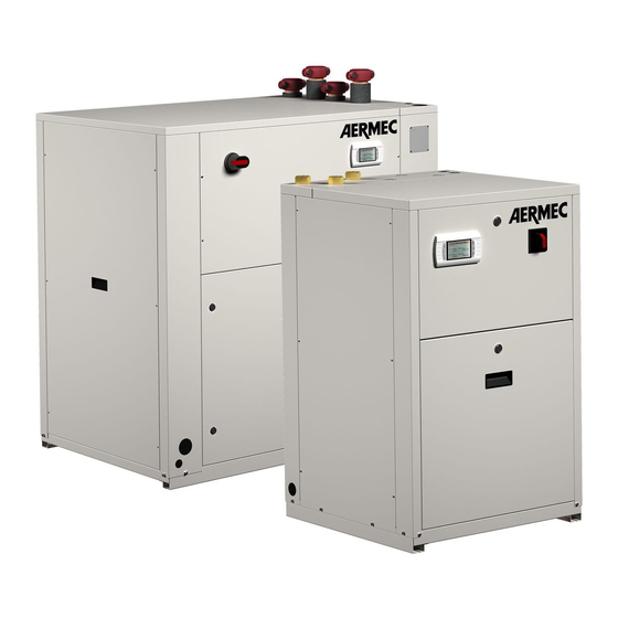
AERMEC WRL 200 Installation & Maintenance Manual
Reversible / chiller - heat pumps
Hide thumbs
Also See for WRL 200:
- Manual (24 pages) ,
- Installation manual (32 pages) ,
- Technical manual (24 pages)
Table of Contents
Advertisement
REVERSIBLE / CHILLER - HEAT PUMPS -
Certificate No.
U8131286304002
Tested according to:
UL 1995:2011
WRL 200-400-500
WRL-H 200-400-500
CHILLER - HEAT PUMPS
WATER/WATER
•
HIGH EFFICIENCY
•
MAXIMUM WATER OUTLET TEMPERATURE 55 °C
•
DESUPERHEATER
•
SUITABLE FOR GEOTHERMAL APPLICATIONS
Installation Maintenance Manual
EN
IWRLI2. 1403. 5890700_01
Advertisement
Table of Contents

Subscribe to Our Youtube Channel
Summary of Contents for AERMEC WRL 200
- Page 1 Installation Maintenance Manual REVERSIBLE / CHILLER - HEAT PUMPS - WRL 200-400-500 WRL-H 200-400-500 CHILLER - HEAT PUMPS WATER/WATER • HIGH EFFICIENCY • MAXIMUM WATER OUTLET TEMPERATURE 55 °C • DESUPERHEATER • SUITABLE FOR GEOTHERMAL APPLICATIONS Certificate No. U8131286304002 Tested according to: UL 1995:2011 IWRLI2.
- Page 3 AERMEC S.p.A AERMEC S.p.A. reserves the right at any moment to make any modifications considered necessary to improve our products and is not obliged to add these modifications to machines that have already been fabricated, delivered or are under construction.
-
Page 4: Table Of Contents
INDEX Sommario Receipt of the product and installation ..........5 1.1. Receipt and handling ................ 5 1.2. Selection and place of installation ........... 5 1.3. Handling ................... 5 1.4. Minimum technical spaces ............... 5 Wrl dimensions tables ............... 6 Anti-vibration position ..............7 Position/dimension connection wrl .......... -
Page 5: Receipt Of The Product And Installation
RECEIPT OF THE PRODUCT AND INSTALLATION 1.1. 1.3. RECEIPT AND HANDLING HANDLING The machine is sent from the factory wrapped with estincoil placed on a loading pallet. Before handling the unit, verify the lifting capacity of the machines used. Handling must be performed by qualified, suitably equipped staff. -
Page 6: Wrl Dimensions Tables
WRL DIMENSIONS TABLES DIMENSIONS WRL 200-400 DIMENSIONS WRL-H 200-400 POSITION Model U.M. 1270 1270 1380 1380 1320 1320 31,5 31,5 33,3 33,3 50,0 50,0 54,3 54,3 52,0 52,0 DIMENSIONS WRL 500 DIMENSIONS WRL-H 500 POSITION Model U.M. 1270 1380 2060... -
Page 7: Anti-Vibration Position
ANTI-VIBRATION POSITION DIMENSIONS WRL 200-400 DIMENSIONS WRL-H 200-400 POSITION Model U.M. 1170 1170 46,1 46,1 DIMENSIONS WRL 500 DIMENSIONS WRL-H 500 POSITION Model U.M. 1899 74,8 IWRLI2_13.04_5890700_00... -
Page 8: Position/Dimension Connection Wrl
POSITION/DIMENSION CONNECTION WRL DIMENSIONS WRL 200-400 DIMENSIONS WRL-H 200-400 POSITION Model U.M. EVAPORATOR CONDENSER DESUPERHEATER 11,8 11,8 Electrical alimentation CONNECTIONS (Ø) 2” 2” 2” 2” Evaporator 2” 2” 2” 2” Condenser 1”½ 1”½ 1”½ 1”½ Desuperheater DIMENSIONS WRL 500 DIMENSIONS WRL-H 500... -
Page 9: Weights And Barycentres
WEIGHTS AND BARYCENTRES DIMENSIONS WRL 200-400 DIMENSIONS WRL 500 DIMENSIONS WRL-H 200-400 DIMENSIONS WRL-H 500 5.1. NO PUMP VERSION Empty weights Running weights Percentage weight distribution on centre of gravity centre of gravity supports (%) weights weights 1164 1235 1024... -
Page 10: External Side Pump Version
DIMENSIONS WRL 200-400 DIMENSIONS WRL 500 DIMENSIONS WRL-H 200-400 DIMENSIONS WRL-H 500 5.3. EXTERNAL SIDE PUMP VERSION Empty weights Running weights Percentage weight distribution on centre of gravity centre of gravity supports (%) weights weights 1020 1289 1034 1359 1059... -
Page 11: Electric Connections
ELECTRIC CONNECTIONS All the electrical operations must be carried out bySTAFF IN POSSESSION OF THE NECESSARY QUALIFICATIONS BY LAW, suitably trained and informed on the risks related The WRL heat pumps are completely wired at to these operations. the factory and only require connection to the electrical mains, downstream from a unit switch, according to that envisioned by the Standards in The characteristics of the electrical lines and of the related components must be... -
Page 12: Control And Commissioning
- Check that the compressor input current is lower Please note that, on request by the Aermec customer or the legitimate owner of the machine, than the maximum indicated in the technical data Commissioning must be performed with table. -
Page 13: Extraordinary Maintenance
After a few hours of functioning, check that EXTRAORDINARY • the liquid indicator indicates the dry circuit MAINTENANCE (dry-green). In the case of partial loss, the WARNING circuit must be emptied completely before Inspection, maintenance and The WRL heat pumps are loaded with R410A gas being re-loaded. - Page 14 IWRLI2_13.04_5890700_00...
- Page 15 IWRLI2_13.04_5890700_00...
- Page 16 Papier 37040 Bevilacqua (VR) - Italy The technical data in the following documentation are not binding. Aermec Via Roma, 996 - Tel. (+39) 0442 633111 reserves the right to make all the Telefax (+39) 0442 93730 - (+39) 0442 93566 modifications considered necessary for improving the product at any time.


Need help?
Do you have a question about the WRL 200 and is the answer not in the manual?
Questions and answers