Table of Contents
Advertisement
Available languages
Available languages
Quick Links
ARTICOLI & APPARECCHI PER MEDICINA
MONITOR PAZIENTE
MULTIPARAMETRO
MODELLO: UP-7000
Manuale d'uso
ATTENZIONE: Gli operatori devono leggere e capire completamente
questo manuale prima di utilizzare il prodotto.
35145
Gima S.p.A.
Via Marconi, 1
20060 Gessate (MI) - Italy
Made in China
Gima S.p.A.
Via Marconi, 1 - 20060 Gessate (MI) Italy
gima@gimaitaly.com - export@gimaitaly.com
www.gimaitaly.com
0476
Advertisement
Chapters
Table of Contents
Troubleshooting

Related Manuals for Gima UP-7000


Summary of Contents for Gima UP-7000
- Page 1 Gima S.p.A. Via Marconi, 1 - 20060 Gessate (MI) Italy gima@gimaitaly.com - export@gimaitaly.com www.gimaitaly.com ARTICOLI & APPARECCHI PER MEDICINA MONITOR PAZIENTE MULTIPARAMETRO MODELLO: UP-7000 Manuale d’uso ATTENZIONE: Gli operatori devono leggere e capire completamente questo manuale prima di utilizzare il prodotto.
- Page 2 PREFAZIONE Uso previsto Questo manuale contiene le istruzioni necessarie per il funzionamento sicuro del prodotto secondo le sue ca- ratteristiche e il suo uso previsto. Al fine di utilizzare il prodotto in modo opportuno e corretto e proteggere il paziente e l’operatore da infortuni, il rispetto delle istruzioni contenute in questo manuale è di massima priorità. In base alla configurazione del dispositivo, alcune funzionalità...
-
Page 3: Table Of Contents
Indice Capitolo 1 Sicurezza ............................. 7 1.1 Informazioni in materia di sicurezza ..................7 1.1.1 Avvertenze ........................7 1.1.2 Precauzioni ........................8 1.1.3 Nota ..........................8 1.2 Simboli del dispositivo ......................8 1.2.1 Lista delle icone sullo schermo ..................8 Capitolo 2 Concetti essenziali ........................ - Page 4 5.2.6 Short trends view (Schermata andamenti recenti) ............. 35 5.2.7 CSM View (Schermata CSM) ..................... 36 Capitolo 6 Allarmi ............................37 6.1 Categorie di allarme ......................37 6.2 Livelli di allarme ........................37 6.3 Indicatori d’allarme ....................... 38 6.3.1 Spia di allarme ......................38 6.3.2 Messaggio di allarme ....................
- Page 5 Capitolo 12 Monitoraggio IBP ........................64 12.1 Introduzione ........................64 12.2 Informazioni in materia di sicurezza ..................64 12.3 Impostare la misurazione IBP ..................... 64 12.3.1 Comprendere l’icona IBP e la scatola Plugin IBP (Opzionale) ........64 12.3.2 Connessione del Kit del trasduttore IBP ..............65 12.4 Comprendere il display IBP ....................
- Page 6 20.1 Utilizzare una stampante ....................104 20.2 Caricamento della carta nella stampante ................. 105 20.3 Attenzione ........................106 20.4 Effettuare la stampa ......................106 20.4.1 Ispezione quotidiana ....................107 20.4.2 Stampa della cronologia delle registrazioni............. 108 20.5 Pulire la testina di stampa ....................109 Capitolo 21 Altre funzioni ...........................
-
Page 7: Capitolo 1 Sicurezza
Capitolo 1 SICUREZZA 1.1 Informazioni in materia di sicurezza Le dichiarazioni riguardanti la sicurezza presenti in questo capitolo fanno riferimento alle informazioni elemen- tari in materia di sicurezza alle quali l’operatore del monitor è tenuto a prestare attenzione e rispettare. Sono presenti dichiarazioni supplementari riguardanti la sicurezza in altri capitoli o sezioni, le quali potrebbero esse- re simili o identiche a quelle che seguono, o specifiche per determinate operazioni. -
Page 8: Precauzioni
1.1.2 Precauzioni I componenti del monitor NON devono essere sostituite autonomamente; la sostituzione con un compo- nente diverso da quelli forniti dal produttore potrebbe causare errori di misurazione. Se necessario, si prega di utilizzare componenti forniti dal produttore o componenti dello stesso modello e caratteristiche degli accessori che sono forniti con il monitor dalla fabbrica, al fine di evitare di compromettere la sicurezza, la biocompatibilità, ecc. -
Page 9: Capitolo 2 Concetti Essenziali
2.1 Descrizione del monitor 2.1.1 Nome e modello del prodotto Nome del prodotto: Monitor paziente multiparametro Modello del Prodotto: UP-7000 2.1.2 Uso previsto Questo Monitor Paziente è uno strumento polifunzionale progettato per monitorare i segni fisiologici vitali di pazienti adulti, bambini e neonati. Grazie alle funzioni di registrazione in tempo reale e di visualizzazione di pa- rametri quali ECG, frequenza cardiaca (HR), pressione sanguigna non-invasiva (NIBP), saturazione funzionale dell’ossigeno (SpO... -
Page 10: Unità Principale
• Possibilità di effettuare il calcolo dell’ossigenazione, della ventilazione e delle funzioni renali; • Possibilità di visualizzazione a schermate multiple, con facilità di spostamento da una all’altra a seconda del monitoraggio da eseguire; • Possibilità di fermare l’immagine della forma d’onda al fine di misurare il segmento ST e analizzare un’arit- mia;... - Page 11 Connettore e icona Lato sinistro Lato destro SERIE II 12 13 Vista anteriore Vista posteriore Connettore e icona Modulo Plugin Sito di installazione Lato sinistro Lato destro...
- Page 12 SERIE III Vista anteriore Vista posteriore Lato sinistro Lato destro...
- Page 13 SERIE IV Vista anteriore Vista posteriore Modulo esteso Lato sinistro Lato destro...
- Page 14 PANNELLO FRONTALE Di seguito le descrizioni delle icone mostrate qui sopra. n° Simbolo Descrizione n° Simbolo Descrizione Pulsante di accensione Tasto stampa/registra Tasto vista schermate Indicatore dell'alimenta- zione CA Indicatore del funziona- mento dell’alimentazione Manopola di navigazione Tasto impostazione schermata oppure oppure Tasto di reset allarme...
-
Page 15: Moduli Plugin (Soltanto Per Monitor Plugin)
• CSM: questo connettore può essere utilizzato come connettore per il cavo del sensore CSM (opzionale). • IBP1, IBP2, IBP3, IBP4: questi connettori possono essere utilizzati come connettori per il cavo del sensore IBP (opzionale). • C.O.: questo connettore può essere utilizzato come connettore per il cavo del sensore della Gittata Cardiaca (optional). - Page 16 Nota: 1. Si prega di fare riferimento ai moduli plugin acquistati per le funzioni dettagliate. 2. Qualora fosse stato acquistato il monitor con la configurazione “Built-in CSM module” (Modulo CSM inte- grato), il monitor acquistato non avrà “Plugin CSM module” (ossia Modulo CSM Plug-and-Play). In tal caso, è...
-
Page 17: Schermo Di Visualizzazione
3) Descrizione delle icone sul Modulo plugin: • CO : trasduttore per la funzione CO . È differente a seconda della diversa configurazione; si prega di fare riferimento al monitor acquistato. • CSM: trasduttore per la funzione CSM. È differente a seconda della diversa configurazione; si prega di fare riferimento al monitor acquistato. -
Page 18: Barra Di Stato
• Area informazioni paziente (come mostrato nell’immagine sopra): il paziente le cui informazioni vengono mostrate nell’Area di indicazione messaggi è il paziente attualmente monitorato dal dispositivo. L’Icona “ ” indica che il paziente è una donna, “ ” che è uomo, “ ”... - Page 19 la finestra impostazione volume bip, la finestra impostazione alimentazione, la finestra impostazione orario del sistema. Finestra a comparsa per le Impostazioni del Volume del Bip Finestra a comparsa per lo Stato Alimentazione Finestra a comparsa per le Impostazioni del Volume dell’Allarme •...
-
Page 20: Area Parametri E Area Forme D'onda
2.4.3 Area parametri e area forme d’onda 1) Area parametri L’area parametri mostra il valore di ogni parametro, l’unità, l’icona, ecc. Spostare la Manopola di navigazione per concentrarsi sul pannello di un determinato parametro; il pannello (come il pannello del parametro ECG mostrato nella figura sottostante) verrà... -
Page 21: Capitolo 3 Istruzioni Per L'uso
• View others: se quest’opzione è selezionata, il monitor può visualizzare le informazioni paziente del monitor di un altro letto attraverso il sistema di monitoraggio centralizzato. • Save Last View (Salvare l’ultima Schermata): Attiva o disattiva la funzione “Save Last View”. Se sele- zionata, la funzione sarà... -
Page 22: Disimballaggio E Controllo
3.1.1 Disimballaggio e controllo 1. Aprire l’imballaggio, estrarre attentamente il monitor e i suoi accessori e posizionarli in una posizione sicura, stabile e facile da sorvegliare. 2. Aprire il manuale utente e disporre gli accessori conformemente all’elenco d’imballaggio. • Verificare eventuali danni agli accessori •... -
Page 23: Accendere Il Monitor
Nome Vita della batteria Monitor paziente Oltre 120 minuti multiparametro Nota: quando il dispositivo è in funzione, sono necessarie almeno 10 ore perché la batteria passi dallo stato di esaurimento al 90% di carica. La batteria fornita con il monitor deve essere ricaricata dopo il trasporto o lo stoccaggio. Di conseguenza, se il monitor viene acceso senza essere connesso all’alimentazione CA, è... -
Page 24: Utilizzo Dei Tasti
3.4 Utilizzo dei tasti 3.4.1 Tasto di accesso rapido • (Oppure ) Tasto Impostazioni Schermata: premere questo tasto sulla scher- mata (quando non sono presenti finestre a comparsa sullo schermo), quindi la finestra di Impostazioni Schermate comparirà sullo schermo. Quando si imposta un determinato parametro, premere la manopola di navigazione, premere la finestra di Impostazioni Schermate, quindi la tastiera di accesso rapido comparirà... -
Page 25: Utilizzare Il Touchscreen
2) Pulsanti per spostarsi tra pagine: : ultima/prima pagina : pagina precedente/successiva Nota: in questo monitor, le funzioni o i pulsanti qui sopra sono simili. Queste informazioni non verranno ripe- tute negli ultimi capitoli. 3) Istruzioni Operative per la Tastiera Virtuale •... -
Page 26: Impostare Le Schermate
3.6 Impostare le schermate La vista schermata generale mostra normalmente dai 3 ai 7 tracciati di forma d’onda nell’Area forma d’onda, e dai 2 ai 7 pannelli parametri nell’area parametri. Ogni tracciato di forma d’onda mostra una specifica forma d’onda del segnale (ad es. forme d’onda ECG, pletismogramma, ecc.), la quale può essere disabilitata. Ogni pannello parametri mostra uno o un gruppo di valori dei parametri e lo stato corrispondente. -
Page 27: Modificare Le Impostazioni Del Sistema
• La finestra impostazioni parametri per ECG, SpO , RESP, TEMP e NIBP; se è stata configurata una funzione opzionale, il monitor mostrerà automaticamente la finestra di impostazione corrispondente (ad es. IBP, C.O., e finestra impostazioni CSM) nella finestra “Menu”. •... -
Page 28: Impostare Data E Ora
4. Altri • Mode (Modalità): selezione della modalità operativa del monitor. Vedere Modalità Operative. • Freeze type (Fermoimmagine): per selezionare una forma d’onda e bloccarne l’immagine sullo schermo. Le opzioni sono “All Waves” (Ogni Forma d’Onda), “EEG”, e “ECG Waves” (Forme d’Onda ECG). Quando viene selezionato “ECG Waves”, il sistema bloccherà... -
Page 29: Impostazioni Di Rete
3.8.3 Impostazioni di rete Selezionare “Menu” “System Settings” “Network”. • Server IP Address: l’indirizzo IP serve a collegarsi a un server di monitoraggio centrale (stazione di lavoro). • Port: il numero di porta al quale il monitor sarà connesso alla stazione di lavoro nel sistema di monitoraggio centrale. -
Page 30: Modalità Operative
ON, ruotare la manopola di navigazione sul Timer per abilitare la stampa a tempo e impostare il valore degli intervalli di stampa nella categoria del ciclo. L’intervallo di stampa può essere impostato tra 5 e 480 minuti; lo step è 5 minuti. Il valore predefinito è 60 minuti. •... -
Page 31: Modificare Un Documento Paziente
4.3 Modificare un documento paziente Selezionare “Menu” ”Patient Info.” ”Edit”. Per modificare un documento paziente è richiesta la password corrispondente; si veda la Sezione 3.9 per i dettagli. Nella finestra “Patient Info” (Informazioni Paziente), premere il pulsante “Edit”, inserire la password corretta, quindi comparirà... -
Page 32: Connessione Al Sistema Di Monitoraggio Centrale
4.6 Connessione al sistema di monitoraggio centrale Se il vostro monitor è connesso al Sistema di Monitoraggio Centrale (CMS): • Tutte le informazioni dei pazienti, i dati delle misurazioni e le impostazioni del monitor possono essere tra- sferite al CMS. •... -
Page 33: General View (Schermata Generale)
sul pulsante “Views” (Schermate), e selezionare una delle etichette schermata (ad es. “Big Font”), premere “Settings” (Impostazioni), quindi la finestra di impostazioni schermate (ad es. finestra “Big Font View Settings” (Impostazioni Schermate Font Allargato)) apparirà sullo schermo. Un metodo alternativo per accedere alla Finestra Impostazioni Schermate, se la schermata specifica è la “Big Font View Settings”... -
Page 34: Big Font View (Schermata Font Allargato)
� Parameter Settings (Impostazioni Parametri): • I parametri 1 e 2 sono assegnati rispettivamente a ECG e SpO , e ciò non può essere modificato. I parametri dal 3 al 7 possono essere impostati su OFF, TEMP, NIBP, RESP ecc. Nota: forma d’onda 1~5 e Parametro 1~5 corrispondono alla forma d’onda 1~5 e Parametro 1~5. -
Page 35: Nibp List View (Schermata Elenco Nibp)
2) All ECG Trace View Settings (Impostazioni Schermata di Tutti i Tracciati ECG): Le 7 forme d’onda preimpostate visualizzate nella schermata sono: ECG I, ECG II, ECG III, ECG aVR, ECG aVL, ECG aVF e ECG V; le forme d’onda 1~7 non sono regolabili. Se è selezionato “3-lead wires” (Cavo a 3 derivazioni), viene mostrata la forma d’onda in cascata;... -
Page 36: Csm View (Schermata Csm)
• I parametri 1 e 2 non sono regolabili, l’impostazione predefinita è rispettivamente ECG e SpO • I parametri 3 ~ 5 possono essere impostati su OFF, TEMP, NIBP, RESP (o CO ) e così via. 5.2.7 CSM View (Schermata CSM) 1) Descrizione: In questa schermata, la forma d’onda predefinita del quarto canale è... -
Page 37: Capitolo 6 Allarmi
Capitolo 6 ALLARMI Gli allarmi, innescati da un parametro vitale che appare anormale o da un problema tecnico del monitor, sono portati all’attenzione dell’utente tramite indicazioni di allarme visive e uditive. 6.1 Categorie di allarme Gli allarmi del monitor possono essere classificati in tre categorie: allarmi fisiologici, allarmi tecnici e messaggi prompt. -
Page 38: Indicatori D'allarme
Allarme tecnico Livello di priorità Origine Episodi di allarme allarme dell’allarme Alto Sistema Batteria scarica, Guasto modulare a SpO , Errore sconosciuto Errore sensore CO , Temperatura del sensore CO troppo elevata Medio ECG/SpO Derivazione/i disattivata/e, Sonda SpO disattivata, il valore di SpO supera l’intervallo di misurazione, HR supera l’intervallo di misura- zione Sensore CO... -
Page 39: Toni Di Allarme Acustico
6.3.4 Toni di allarme acustico Il tono di allarme si distingue dal tono della frequenza cardiaca, dal tono tasti e dal tono delle pulsazioni. i toni di allarme per i livelli di allarme sono come seguono: • Allarme di priorità elevata: Bip+Bip+doppio+Bip+pausa+Bip+Bip+doppio+Bip •... -
Page 40: Modificare Il Volume Dell'allarme
6.3.6 Modificare il volume dell’allarme Impostare il volume dell’allarme. Fase 1: Selezionare “Alarm” “Others”. Fase 2: In “Others”, selezionare “Alarm Volume”. L’intervallo di impostazione è “0 ~ 10”, lo step è 1. Il volume è preimpostato a 5. “10” è il volume massimo. ... -
Page 41: Intervallo Di Impostazione Del Limite Di Allarme Superiore E Inferiore
- All on: selezionarlo per attivare la funzione di allarme per tutti i parametri. Questa operazione richiede una password. - All off: selezionarlo per disattivare la funzione di allarme per tutti i parametri. Questa operazione richiede una password, ma si consiglia di non disattivare completamente la funzione di allarme. Nota: 1. -
Page 42: Valore Preimpostato Del Limite Di Allarme
NIBP (Unità) kPa Adulto Bambino Neonato Limite Superiore (Limite inferiore+0,1)~37,3 (Limite inferiore+0,1)~26,7 (Limite inferiore+0,1)~18,0 Limite Inferiore 3,9~(Limite superiore-0,1) 3,9~(Limite superiore-1) 3,9~(Limite superiore-0,1) Limite Superiore (Limite inferiore+0,1)~32,3 (Limite inferiore+0,1)~22,0 (Limite inferiore+0,1)~14,7 Limite Inferiore 2,7~(Limite superiore-0,1) 2,7~(Limite superiore-0,1) 2,7~(Limite superiore-0,1) Limite Superiore (Limite inferiore+0,1)~30,1 (Limite inferiore+0,1)~20,0 (Limite inferiore+0,1)~13,3 Limite Inferiore 1,3~(Limite superiore-0,1) 1,3~(Limite superiore-0,1) 1,3~(Limite superiore-0,1) - Page 43 Limite Superiore 120 mmHg 90 mmHg 90 mmHg Limite Inferiore 50 mmHg 40 mmHg 30 mmHg Limite Superiore 160 mmHg 110 mmHg 100 mmHg Limite Inferiore 50 mmHg 40 mmHg 30 mmHg Limite Superiore 100% 100% 100% Limite Inferiore Limite Superiore +1.00mV +1.00mV +1.00mV...
-
Page 44: Testare Gli Allarmi
Limite Superiore EtAA2 Limite Inferiore Limite Superiore Ins.AA2 Limite Inferiore 1. Ad eccezione del volume dell’allarme acustico, che può essere regolato, le altre caratteristiche degli allarmi, quali le impostazioni della priorità degli allarmi, la luce degli allarmi lampeggianti, ecc., non possono essere regolate dagli utenti. -
Page 45: Preparazione Al Monitoraggio Ecg
È proibito applicare elettrodi a pazienti che presentino lesioni o gangrena. Per quanto riguarda le misurazioni su pazienti portatori di pacemaker, il misuratore della frequenza cardiaca ignora il battito del pacemaker grazie alla funzione di inibizione del battito del pacemaker, ma nel caso di pacemaker con battito mancante, la funzione di inibizione potrebbe non essere del tutto efficace. -
Page 46: Posizionamento Degli Elettrodi Ecg
7.3.2 Posizionamento degli elettrodi ECG Posizionamento degli elettrodi Le derivazioni ECG e le loro posizioni corrispondenti sono le seguenti: Connessione elettrodo 1 Connessione elettrodo 2 (Standard CEI) (Standard AHA) Posizione elettrodo sulla superficie Etichetta su Etichetta su del corpo Codice colore connessione Codice colore connessione... -
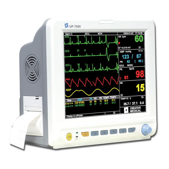
Page 47: Comprendere Il Display Ecg
7.4 Comprendere il display ECG Il vostro display potrebbe essere configurato in modo da apparire leggermente diverso. Forma d’onda ECG • “ECG”: etichetta parametro. • “III”: Derivazione ECG. III significa derivazione ECG III. • “25mm/s”: velocità di scansione forma d’onda ECG; l’unità è “mm/s”. •... -
Page 48: Rilevamento Di Aritmie E Apprendimento Del Modello
Note: 1. Per differenti finestre di impostazione ECG, e quando la modalità di filtraggio ECG è impostata su “OPER”, voci quali “Notch”, “Wires”, “Lead” e “Pacer” sono visualizzate in grigio e non sono regolabili. “Notch” indica le impostazioni correnti, “Wires” è preimpostato su “3 lead wires” (Cavo a 3 derivazioni), “Lead” è preimpostato sulla derivazione “II”, e “Pacer”... -
Page 49: Comprendere La Tipologia Di Arr
tempo l’apprendimento del dispositivo sarà terminato, l’icona diventerà “ ”. La forma d’onda dell’aritmia rilevata verrà visualizzata sul terzo o ultimo canale di forma d’onda ECG; nel caso in cui vi sia soltanto un canale di forma d’onda ECG, la forma d’onda dell’aritmia rilevata verrà visualizzata nuovamente e la sua immagine bloccata su questo canale per 8 secondi. -
Page 50: Monitoraggio Del Segmento St
7.7 Monitoraggio del Segmento ST Misurazione Manuale del Segmento ST: L’operatore può utilizzare la Manopola di Navigazione per eseguire manualmente la misurazione del segmento ST; il valore verrà visualizzato con “S-T+0.xxx mV”. Sullo schermo sono presenti 2 cursori a croce. Quando la croce è... -
Page 51: Informazioni In Materia Di Sicurezza
8.2 Informazioni in materia di sicurezza Durante il monitoraggio della respirazione del paziente, si consiglia di utilizzare il cavo ECG chiamato “non- OR”, il quale non possiede resistori integrati per evitare la perdita di energia della scarica del defibrillatore. In caso contrario, i risultati del monitoraggio della respirazione risulterebbero meno accurati. -
Page 52: Capitolo 9 Monitoraggio Nibp
Nota: quando “Wires” è impostato su “12-lead” nelle impostazioni ECG, “Apnea” può essere impostato su OFF, 10, 15, 20, 25, 30, 35 e 40. • Source (Sorgente): Sorgente del segnale di respirazione. Questa voce è preimpostata su “CO ” se la funzione di monitoraggio CO è... -
Page 53: Restrizioni Alla Misurazione
nata, in quanto ciò potrebbe causare danni agli arti. Se il paziente si muove o soffre di tremiti, ipercinesi o aritmia, ciò potrebbe provocare un aumento nel tem- po di gonfiaggio del palloncino, il che potrebbe non soltanto prolungare il tempo di misurazione, ma anche causare lividi, ipossiemia e nevralgie alla parte avvolta dal bracciale per via dell’attrito. -
Page 54: Avviare E Arrestare Le Misurazioni
• Ricordarsi di svuotare l’aria residua nel bracciale prima di cominciare la misurazione. • Posizionare il bracciale in modo tale che il simbolo dell’arteria “ ” si trovi in un punto dove sia possibile rilevare la più chiara pulsazione dell’arteria brachiale. •... -
Page 55: Comprendere I Valori Nibp
6. Quando viene monitorato un paziente adulto, il dispositivo potrebbe non restituire una misurazione della pressione corretta se è selezionata la modalità paziente Bambino o Neonato. 7. Quando viene effettuata una misurazione NIBP su un paziente bambino o neonato, l’operatore deve sele- zionare la corretta tipologia paziente a seconda del paziente (fare riferimento al menu impostazioni NIBP) e NON mantenere l’impostazione di tipologia paziente Adulto. -
Page 56: Capitolo 10 Monitoraggio Della Saturazione Dell'ossigeno (Spo 2 )
mized Multi-cycle” (Multi-ciclo Personalizzato), il monitor salverà questa impostazione quando il monitor verrà spento. • Cycle: ipuò essere impostato soltanto su modalità “AUTO”. Ciclo indica l’intervallo di tempo tra le misura- zioni quando la modalità di misurazione è impostata su Auto. Le opzioni di Ciclo sono: 1 min, 2 min, 3 min, 4 min, 5 min, 6 min, 7 min, 8 min, 9 min, 10 min, 15 min, 20 min, 25 min, 30 min, 35 min, 40 min, 45 min, 50 min, 55 min, 1 h, 1,5 h, 2 h, 2,5 h, 3 h, 3,5 h, 4 h, 4,5 h, 5 h, 5,5 h, 6 h, 6,5 h, 7 h, 7,5 h e 8 h. -
Page 57: Informazioni In Materia Di Sicurezza
d’onda e valori digitali di SpO e frequenza delle pulsazioni che vengono visualizzati sullo schermo. 10.2 Informazioni in materia di sicurezza Un utilizzo continuo del sensore SpO può provocare fastidio o dolore, specialmente negli individui con problemi microcircolatori. Si consiglia di NON applicare il sensore nello stesso punto per più di due ore; si prega di verificare il punto di monitoraggio ogni 1 o 2 ore per verificare l’integrità... -
Page 58: Applicare Il Sensore
simetro o di un sensore SpO . Tuttavia, può essere utilizzato per controllare il grado di accuratezza con cui un particolare ossimetro riproduce la curva di calibratura. Prima di verificare l’ossimetro con un tester funzionale, chiedere prima al costruttore quale curva di calibratura è utilizzata. Se necessario, richiedere al costruttore la curva di calibratura dedicata e caricarla nel tester. - Page 59 Tipo 3: Sensore SpO in gomma per dita, Adulto/Bambino (A) Tenere il sensore con l’apertura verso il dito del paziente; il sensore deve essere orientato in modo tale che il lato del sensore con il segno della punta del dito sia posizionato in alto. (B) Inserire il dito del paziente nel sensore fino a che la punta dell’unghia vada ad appoggiarsi sull’arresto del sensore.
-
Page 60: Comprendere Il Display Spo E Il Display Pr
Mignolo Fascia del piede Fascia del piede Mignolo Fascia della caviglia Fascia della caviglia Piede sinistro (la fascia passa sotto il piede) Piede destro (la fascia passa sopra al piede) 2) Utilizzare la fascia della caviglia per fissare il cavo del sensore sulla caviglia o gamba. Non stringere ecces- sivamente. -
Page 61: Modificare Le Impostazioni Spo
10.6 Modificare le impostazioni SpO e PR Selezionare “Menu” “SpO ” per accedere alle impostazioni SpO • SE Threshold (%): imposta la soglia di desaturazione dell’ossigeno (%); l’intervallo dei valori va da 1 a 12, lo step è 1. L’impostazione predefinita è 3 (%). •... -
Page 62: Capitolo 11 Monitoraggio Della Temperatura
Note: 1. Quando si inserisce il dito nella sonda, apparirà l’icona di ricerca della pulsazione “ ” nella parte supe- riore del pannello SpO . Tuttavia, una volta che apparse le letture SpO /PR, o una volta rimosso il dito/la sonda sia stato rimosso, l’icona “... -
Page 63: Comprendere Il Display Temp
lizzato. Il sensore di temperatura potrebbe avere diverse forme per la misurazione della temperatura corporea esterna ed interna rispettivamente. Valore normale della temperatura corporea esterna: 36,5°C ~ 37°C; Note: � Per la sonda della temperatura corporea esterna, collegare il sensore TEMP al paziente. Se il sensore TEMP non è... -
Page 64: Capitolo 12 Monitoraggio Ibp
Capitolo 12 MONITORAGGIO IBP 12.1 Introduzione Il monitoraggio invasivo della pressione sanguigna (IBP) è una misurazione diretta della pressione arteriosa o venosa del paziente. Ciò comporta l’inserimento di un catetere direttamente in una vena, arteria o altra area, il quale viene collegato ad un trasduttore di pressione per la misurazione della pressione sistolica, diastolica e della pressione sanguigna media. -
Page 65: Connessione Del Kit Del Trasduttore Ibp
Le icone “IBP1” e “IBP2” rappresentano i connettori di IBP1 e IBP2. Se la scatola Plugin è inserita nell’allog- giamento di sinistra, “IBP1” e “IBP2” verranno visualizzati sullo schermo del monitor. Il connettore sarà diverso per via della differente configurazione, si prega di fare riferimento al monitor acquistato. I contrassegni “IBP1”... -
Page 66: Modificare Le Impostazioni Ibp
Pannello IBP: Simbolo IBP e unità Posizione di misurazione Pressione sistolica Pressione arteriosa media Pressione diastolica Informazioni di allarme IBP • Le informazioni di allarme IBP saranno visualizzate nell’area informazioni allarmi. • Allarme tecnico: “Probe off” (Sonda disattivata), ecc. • Allarme fisiologico: “IBPL1 Low SYS” (IBPL1 SYS bassa), ecc. 12.5 Modificare le impostazioni IBP Selezionare “Menu”... -
Page 67: Informazioni In Materia Di Sicurezza
Il monitor determina la concentrazione di CO nei gas respiratori attraverso la misurazione della quantità di luce assorbita da tali gas. Il valore EtCO rilevato è visualizzato come valore numerico espresso in millimetri di mercurio (mmHg), in percentuale (%), o in kilopascal (kPa). È inoltre possibile visualizzare un tracciato CO (capnogramma), uno strumento clinico utile a stimare l’integrità... -
Page 68: Connessione Del Sensore Co Sidestream
il funzionamento del sensore CO Quando si sostituisce il tubo di campionamento, è consigliabile scegliere il tubo di campionamento stan- dard con funzione di deumidificazione. Il tubo di campionamento senza funzione di deumidificazione può ostruirsi facilmente a causa di un’eccessiva umidità. (Durata d’uso: tubo di campionamento ordinario: 6~12 ore;... - Page 69 3. Configurazione preimpostata della Tubazione Adattatore di campionamento Tubo di deumidificazione Cannula di campionamento Filtro Cella di campionamento Adattatore e Cannula di Campionamento (Monouso) Prolunga del tubo respiratorio necessaria al collegamento con la cannula di campionamento (monouso) Connettore Wye 4. Kit opzionali della cannula di campionamento (1) Kit cannula di campionamento con connettore a T Connettore Aria Adattatore...
-
Page 70: Mainstream
(3) Kit Cannula Sidestream Orale 13.3.2 Connessione del Sensore CO Mainstream Cavo sensore Adattatore Sensore CO Dimostrazione della Connessione Sensore CO Mainstream 1. Estrarre il Sensore CO e inserire il Cavo del Sensore CO nel connettore denominato “CO ” sul pannello connettore del monitor;... -
Page 71: Restrizioni Alla Misurazione
13.4 Restrizioni alla misurazione I seguenti fattori potrebbero influenzare l’accuratezza della misurazione. • Perdite o sfiati interni di gas campionati • Urto meccanico • Pressione ciclica fino a 10 kPa (100 cm H • Altre eventuali sorgenti di interferenza. 13.5 Risoluzione dei problemi del sistema di campionamento CO Sidestream Quando il sistema di campionamento del modulo CO non funziona correttamente, verificare che la linea di... - Page 72 X1 scala di forma d’onda con guadagno di base X1/2 mezza scala del guadagno di base X2 scala doppia del guadagno di base scala quadrupla del guadagno di base • Speed (Velocità): La velocità di scansione della forma d’onda di respirazione; 2 opzioni: 6.25mm/s e 12.5 mm/s.
-
Page 73: Capitolo 14 Monitoraggio Della Gittata Cardiaca (C.o.)
Capitolo 14 MONITORAGGIO DELLA GITTATA CARDIACA (C.O.) 14.1 Introduzione La funzione di Gittata Cardiaca (C.O.) misura in modo invasivo la gittata cardiaca e altri parametri emodinamici mediante il metodo della termodiluizione. Una soluzione fredda di cui si conosce volume e temperatura viene iniettata nell’atrio destro attraverso la porta prossimale di un catetere dell’arteria polmonare. -
Page 74: Procedura Di Misurazione C.o
14.3.2 Procedura di misurazione C.O. 1. Collegare il cavo al connettore C.O. del monitor. Connettere il catetere e la sonda per la temperatura al cavo C.O. come mostrato nella figura seguente. Collegare il cavo C.O. Catetere al connettore C.O. Connettore per la sonda di temperatura della soluzione Cavi “... -
Page 75: Modificare Le Impostazioni C.o
14.4 Modificare le impostazioni C.O. Preparazione: Prima di effettuare una misurazione, impostare i seguenti parametri come di seguito. Selezionare “Menu” “C.O.” “Parameter” per accedere alle impostazioni dei parametri C.O. Floating Catheter (Catetere a Palloncino): • Brand: marca del catetere. •... - Page 76 • C.O.(l/min): Gittata cardiaca (volume del sangue al minuto; il valore normale è 4-8 l/min). • Examin. Records: visualizza il risultato della misurazione attuale e la cronologia. Tali dati saranno perduti se il monitor verrà spento. Procedura per rivedere la cronologia delle registrazioni dell’esame: Menu History Records ...
-
Page 77: Fattori Che Influenzano La Misurazione C.o
Nota: La misurazione C.O. Corrente verrà mostrata nella tabella “Examin. Records” (Esamina registrazioni) e salvata nella cronologia. Quando il dispositivo verrà spento, il contenuto della tabella “Examin. records” sarà cancellato, ma la cronologia rimarrà disponibile. La cronologia include il codice paziente, il tempo di misura- zione, TI, TB, C.O., C.I., e la forma d’onda BT. -
Page 78: Restrizioni Alla Misurazione
15.3 Restrizioni alla misurazione I seguenti fattori potrebbero influenzare l’accuratezza della misurazione. • Perdite o sfiati interni di gas campionati • Urto meccanico • Pressione ciclica fino a 10 kPa (100 cm H • Altre eventuali sorgenti di interferenza 15.4 Impostare la misurazione AG La funzione MultiGas descritta comprende il Gas anestetico. - Page 79 5. Collegare il connettore femmina di 15mm dell’adattatore per le vie aeree IRMA al tubo endotracheale del paziente. In alternativa, collegare un HME (Scambiatore di Calore e Umidità) tre il tubo endotracheale del paziente e la sonda IRMA. Posizionare un HME di fronte alla sonda IRMA serve a proteggere l’adattatore per le vie aeree da secrezioni e effetti del vapore acqueo, e elimina il bisogno di cambiare l’adattatore.
- Page 80 Controllo pre-utilizzo Controllare sempre le letture del gas e delle forme d’onda sul monitor prima di collegare l’adattatore per le vie aeree IRMA al circuito di respirazione. Effettuare il controllo dell’aderenza del circuito del paziente con la sonda IRMA inserita nell’adattatore per le vie aeree IRMA.
-
Page 81: Istruzioni Per L'analizzatore Sidestream Phasein Isa
NON utilizzare l’adattatore per le vie aeree IRMA con inalatori aerosol dosati o farmaci nebulizzati in quanto ciò potrebbe influenzare la trasmissione della luce della finestra dell’adattatore per le vie aeree. Sostituire l’adattatore per le vie aeree se all’interno dell’adattatore è presente condensa. ... -
Page 82: Comprendere Il Display Ag
4. Procedura di azzeramento L’analizzatore di gas infrarossi necessita di assicurare un livello zero di riferimento dei dati di monitoraggio di O e agenti anestetici (AA). Questa calibrazione a zero si chiama azzeramento. L’analizzatore sidestream ISA è destinato all’esecuzione dell’auto azzeramento spostando il gas di campiona- mento dal circuito respiratorio all’aria ambiente. -
Page 83: Modificare Le Impostazioni Ag
Pannello C.O. (opzionale): Concentrazione di N2O Concentrazione primaria di gas alla fine dell’espirazione anestetico alla fine dell’espirazione Concentrazione secondaria Concentrazione di CO di gas anestetico alla fine alla fine dell’espirazione dell’espirazione Frazione della Frazione della concen- concentrazione trazione di gas anestetico di CO inspirata secondario inspirato... -
Page 84: Capitolo 16 Monitoraggio Csm
acustico. Se questo è impostato su OFF, l’icona “ ” verrà visualizzata nell’angolo in basso a sini- stra del Pannello Respirazione. L’impostazione predefinita è 20s. (2). Quando il monitoraggio AG è OFF: fare riferimento alla sezione Modificare le Impostazioni RESP. •... - Page 85 quantità viene inoltre analizzato come parametro separato (β-α). α rapporto = 1n (E30-42.5Hz/E6-12Hz) β rapporto = 1n (E30-42.5Hz/E11-21Hz) Il monitor valuta anche online la quantità di soppressione burst (BS) ad ogni intervallo di trenta secondi dell’EEG. Questa misurazione quantifica la quantità delle caratteristiche del periodo EEG “silent” (silente) o “flat” (piatto) del più...
-
Page 86: Processi Csm
bloccanti neuromuscolari non possono mostrare movimenti quale segno di risveglio, il CSI è uno strumento valido nella loro gestione anestetica. • Indicatore BS% Il monitor include un indicatore di soppressione burst per mostrare i periodi in cui l’EEG è isoelettrico o “flat” (piatto). -
Page 87: Modificare Le Impostazioni Csm
Caso (3): per pazienti bambini Spalmare acqua pulita sulla pelle, quindi ripulire la cute con cotone o garza. Infine, posizionare gli elettrodi. Fase 3: posizionare gli elettrodi Il posizionamento dei tre elettrodi viene descritto qui di seguito. L’avanzata tecnica di elaborazione del segnale assicura che la distanza tra gli elettrodi possa essere fino a 2 cm (0,78 in) per ottenere un valore CSI. -
Page 88: Capitolo 17 Analisi
nutenzione), “Injection” (Iniezione) e “End Maintenance” (Fine manutenzione). • Renumber: per rinumerare la tipologia di episodio selezionato. • EEG Range (Gamma EEG): per impostare la gamma d’ampiezza EEG; le opzioni sono 20, 40, 80 e 160; l’impostazione predefinita è 80. •... -
Page 89: Grafico Di Andamento
17.2 Grafico di andamento La finestra “Trend Graph” (Grafico di andamento) viene mostrata come nella figura successiva. Finestra del Grafico di Andamento Parameter: selezionare un parametro per rivedere il relativo grafico; le opzioni sono: HR, SpO , RR, ST, TEMP, ecc. -
Page 90: Forma D'onda Ecg
Finestra del Grafico di Andamento NIBP “S”, “D”, “M”: le abbreviazioni per pressione sistolica, pressione diastolica e pressione arteriosa media rispet- tivamente. Il colore della lettera corrisponde al colore della forma d’onda. xx/yy: numero della registrazione visualizzata / registrazioni totali. 17.4 Forma d’onda ECG Il dispositivo può... -
Page 91: Registrazioni Csm (Opzionale)
17.7 Registrazioni CSM (opzionale) Le registrazioni CSM possono essere riviste su “Trends” (Andamenti) e “Events” (Episodi). La finestra di analisi “CSM Records” (Registrazioni CSM) preimpostata si trova in “Trends”. Tutte le registrazio- ni CSM (compresi CSI, SQI, EMG% e BS%) e EEG del paziente che si sta monitorando possono essere riviste. CSM trend graph recall Registrazioni CSM---per Andamenti Nella finestra come mostrato nella figura sopra, il posizionamento della misurazione del grafico di andamento... -
Page 92: Analisi Della Cronologia Delle Registrazioni C.o
Registrazioni CSM---per Episodi Se si rivedono le registrazioni CSM per Episodi, il numero, l’ora e il tipo di episodio saranno elencati nella fi- nestra “CSM Records”. 17.8 Analisi della cronologia delle registrazioni C.O. Elenco delle registrazioni CSM Descrizione: Selezionare una data compreso “Year”, “Month” e “Day” (anno, mese e giorno) ruotando e premendo la ma- nopola di navigazione. -
Page 93: Capitolo 18 Calcoli
Nella finestra Registrazioni CSM, premere Tasto Stampa per stampa tutto l’elenco delle Registrazioni CSM che è mostrato nella finestra. Se “ ” è selezionato, verranno stampati i dati CSM registrati e la forma d’onda selezionati. Capitolo 18 CALCOLI 18.1 Introduzione Il vostro monitor dispone della funzione di calcolo. - Page 94 Questo monitor fornisce il calcolo della dose per 10 tipi di farmaci: AMINOFILLINA, DOBUTAMINA, DOPAMI- NA, EPINEFRINA, EPARINA, ISOPROTERENOLO, LIDOCAINA, NOLIPREL, NITROGLICERINA e PITOCINA. � Il Calcolo della Dose dei Farmaci utilizza le seguenti formule: MC = Gross ÷ Cubage (Lordo ÷ Cubatura) (D/m) = (D/h) ÷...
-
Page 95: Calcolo Dell'ossigenazione
Finestra di Titolazione Sono presenti 3 caselle modificabili nella parte in basso a sinistra della finestra per il recupero dei dettagli della Tabella di Titolazione. • Reference: per rendere le voci una variabile indipendente, lasciando le altre come variabili dipendenti. Sono possibili 3 opzioni: “Dose”, “DS-Drop Speed”... - Page 96 Le voci di ingresso comprendono C.O. (Gittata cardiaca), FiO2 (Percentuale di ossigeno inspirata), PaO2 (Pres- sione parziale di ossigeno), PaCO (Pressione parziale di anidride carbonica), Hb (Emoglobina), CaO2 (Con- tenuto di ossigeno nel sangue arterioso), CvO2 (Contenuto di ossigeno nel sangue misto), VO2 (Consumo di ossigeno), RQ (quoziente respiratorio), ATMP (pressione atmosferica), peso e altezza.
- Page 97 Procedure Operative: Inserire il valore per ciascuna voce di ingresso, e premere “Calculate”, quindi il monitor calcolerà il parametro in base alla forma di calcolo e risultato verrà visualizzato sullo schermo. Successivamente, premere “Range” per visualizzare l’intervallo per ogni parametro. Note: 1) Il risultato di ogni parametro verrà...
-
Page 98: Calcolo Della Ventilazione
18.5 Calcolo della ventilazione Dalla finestra “Menu”, si può accedere alla finestra di “Ventilation Calculation” (Calcolo ventilazione). Finestra di calcolo ventilazione Le voci di ingresso comprendono FiO (percentuale di ossigeno inspirata), RR (frequenza respiratoria), PeCO (pressione di CO di fine espirazione), PaCO (pressione parziale di anidride carbonica), PaO2 (pressione arte- riosa dell’ossigeno), TV (volume corrente), RQ (quoziente respiratorio), ATMP (pressione atmosferica). - Page 99 Fare riferimento alla seguente tabella per definizioni, unità e intervallo di regolazione delle voci di ingresso. Parametri Definizione Formula del Calcolo Unità Intervallo Pressione parziale dell’ossigeno *(ATMP - 47) – (PaCO / RQ) mmHg —— nell’area alveolare Differenza tra la pressione di *(ATMP - 47) –...
-
Page 100: Calcolo Della Funzionalità Renale
Intervallo Calcolo della ventilazione---Intervallo di riferimento 18.6 Calcolo della funzionalità renale Dalla finestra “Menu”, è possibile accedere alla finestra “Renal Function Calculation” (Calcolo della Funziona- lità Renale). Finestra di Calcolo della Funzionalità Renale Le voci di ingresso comprendono URK (livello del potassio dell’urina), URNa (livello del sodio dell’urina), Urine (urina raccolta nelle 24 ore), Posm (pressione osmotica del plasma), Uosm (pressione osmotica dell’urea), Ser- Na (sodio sierico), SCr (creatinina sierica), UCr (creatinina urinaria), BUN (azoto ureico), Height (peso) e Weight (altezza). - Page 101 Fare riferimento alla seguente tabella per definizioni, unità e intervallo di regolazione delle voci di ingresso. Voce di ingresso Definizione Intervallo di regolazione Unità Livello del potassio dell'urina 1—9999 mmol/L URNa Livello del sodio dell'urina 0—9999 mmol/L Urine Urina raccolta nelle 24 ore 0—5000 ml/24h Posm...
-
Page 102: Hemo (Calcoli Emodinamici)
Risultato Unità Calcolo della Funzionalità Renale---Risultato del calcolo Intervallo Calcolo della Funzionalità Renale---Intervallo di riferimento 18.7 HEMO.(Calcoli emodinamici) Selezionare “Menu” “Hemo.” per accedere alla finestra dei calcoli emodinamici, come mostrato nella figura sottostante. qui è possibile derivare CI, SV, SVR ecc. in base al peso, all’altezza, HR, ecc. - Page 103 • Impostazioni Emodinamiche Impostazioni Emodinamiche Parametri da impostare per calcoli emodinamici: • C.O.: gittata cardiaca. • MAP: pressione arteriosa media. • Height: altezza del paziente. • MVP: pressione venosa media. • Weight: peso del paziente. • PAW: pressione capillare polmonare •...
-
Page 104: Capitolo 19 Laccio Emostatico
Capitolo 19 LACCIO EMOSTATICO Selezionare “Menu” “Tourniquet” per accedere alla finestra del Laccio emostatico Impostazioni Laccio emostatico Conto alla Rovescia • Pressure: il limite superiore della pressione del bracciale durante il gonfiaggio. Il monitor arresterà il gon- fiaggio se la pressione del bracciale supera tale valore. Lo step è 10 mmHg (1,3 kPa); l’intervallo e il valore predefinito per i diversi tipi di paziente in base all’età... -
Page 105: Caricamento Della Carta Nella Stampante
Istruzioni per il funzionamento della stampante: Indicatore di alimentazione: La luce verde indica che la stampante è accesa. Quando il monitor non è alimen- tato, la luce verde è spenta. Indicatore di errore: una luce rossa stabile per indicare che non vi è carta nella stampante, oppure che la carta di stampa non è... -
Page 106: Attenzione
Caricare la carta nella stampante: 1: Premere e tenere premuto il pulsante della cartuccia per aprire la cartuccia della carta; 2: Inserire correttamente la carta nella stampante, tirare la carta fuori dalla stampante di 2 cm. 3: Chiudere il coperchio della stampante lungo la direzione della freccia. Carta di stampa 20.3 Attenzione ... -
Page 107: Ispezione Quotidiana
20.4.1 Stampare i dati in tempo reale Schermata/finestra Indice visualizzata Informazioni titolo Informazioni Forma d'onda/Testo General view - Stampa in tempo reale della forma (Schermata generale) d’onda di 10 secondi: - Identificatore dati: “==Real time==”; - Il primo tracciato: forma d’onda ECG Big font view (Scher- - Info paziente: Codice paziente, nome, genere, - Il secondo tracciato: Forma d’onda... -
Page 108: Stampa Della Cronologia Delle Registrazioni
20.4.2 Stampa della cronologia delle registrazioni Indice Finestra di revisione dati Informazioni titolo Informazioni Forma d'onda/Testo - Identificatore dati: “==ARR==”; Stampa le 6 voci nell’elenco - Info paziente: Codice paziente, nome, genere, episodi ARR, compreso data Finestra episodio ARR gruppo del paziente, peso, altezza e data di e ora, tipologia di aritmia, nascita;... -
Page 109: Pulire La Testina Di Stampa
20.5 Pulire la testina di stampa Dopo vari usi della stampante, pezzetti di carta potrebbero depositarsi sulla testina di stampa, compromet- tendo la qualità di stampa e accorciando il ciclo vitale del cilindro. Per pulire la testina di stampa, seguire la seguente procedura: 1. -
Page 110: Manutenzione Della Batteria
La capacità della batteria integrata è limitata. Se la carica della batteria è insufficiente, un allarme tecnico verrà innescato e il messaggio relativo visualizzato. In questo caso, connettere il monitor alla sorgente di alimenta- zione CA esterna. In caso contrario, il monitor si spegnerà automaticamente prima che la carica della batteria sia completamente esaurita. -
Page 111: Disinfettare Il Dispositivo E Gli Accessori
• Isopropanolo al 70% Per pulire il dispositivo, seguire le seguenti disposizioni: � Prima della pulizia, spegnere il monitor e scollegare il cavo di alimentazione. • Mantenere il monitor lontano dalla polvere. • Si raccomanda di pulire la struttura esterna e di mantenere pulito lo schermo del dispositivo. È consentito esclusivamente l’utilizzo di detergenti non corrosivi, quali l’acqua pulita. -
Page 112: Manutenzione Ordinaria
• Verificare tutte le funzioni del monitor che si prevede saranno utilizzate per il monitoraggio del paziente, e accertarsi che siano in buone condizioni di funzionamento; • Accertarsi che il monitor sia correttamente messo a terra. • Prestare particolare attenzione alle fluttuazioni della tensione di alimentazione locale. Se necessario, si rac- comanda di utilizzare un regolatore della tensione di alimentazione. - Page 113 Misuratore della pressione sanguigna al mercurio Bracciale NIBP con duplice tubo dell’aria Tubo per l’aria Tubo per l’aria Tubo per l’aria Tubo per l’aria Sfogo d’aria Valvola manuale Software Modulo Aumenta manualmente per il test Gonfiaggio NIBP la pressione mediante il del modulo palloncino palloncino gonfiabile...
-
Page 114: Calibrazione Ibp (Opzionale)
Dopo la verifica, premere il pulsante per ritornare alla modalità di funzionamento normale, proseguire quindi con un’altra operazione, altrimenti il tasto NIBP non sarà valido. La verifica dell’accuratezza della pressione deve essere eseguita da un tecnico autorizzato. L’esecuzione della verifica non è... -
Page 115: Capitolo 25 Accessori
Capitolo 25 ACCESSORI Controllare che gli accessori e il loro imballaggio non presentino segni di danno. Non utilizzarli se viene rile- vato un qualsiasi danno Nome del componente Note Cavo ECG Elettrodo ECG Sensore SpO Sensore a dito SpO Adulto Opzionale Sensore a dito SpO... -
Page 116: Resp
9. Rigetto dell’impulso pacemaker: Rifiuta tutti gli impulsi di ampiezza da ±2mV a ±700mV e di durata da 0,1 a 2 ms senza oltrepassare; 10. Selezione sensibilità: ×1/4, ×1/2, ×1, ×2, ×4 e AUTO ×1/2, 5mm/mV tolleranza: ±5% ×1, 10mm/mV tolleranza: ±5% ×2, 20mm/mv... -
Page 117: Spo
10. Precisione NIBP: Differenza media massima: ±5 mmHg Mx. Deviazione Standard: 8 mmHg 11. Modalità di misurazione: Manual, Auto, STAT, Customized Multi-cycle (Multi-ciclo personalizzato) 12. Gamma di impostazione di allarme NIBP: vedere Sezione Allarmi 26.5 SpO 1. Trasduttore: LED a doppia lunghezza d’onda Lunghezza d’onda: Luce rossa: 663 nm, Luce infrarossa: 890 nm. -
Page 118: Csm
*NOTA: Temperatura gas a 25 °C per Sidestream; Temperatura gas a 35 °C per Mainstream 8. Frequenza di flusso: 50 ml/min ±10 ml/min (Sidestream) 26.8 CSM 1. Sensibilità EEG: ±400 μV 2. Livello di disturbo: <2μVp-p, <0,4μV RMS, 1250 Hz 3. - Page 119 (2) Analizzatore sidestream ISA (ISA CO , ISA AX+, ISA OR+) Intervallo Precisione 0~15 vol% ±(0,2 + 2% della lettura) vol% 0~100 vol% ±(0,2 + 2% della lettura) vol% HAL, ISO, ENF 0~8 vol% ±(0,15 + 5% della lettura) vol% 0~10 vol% ±(0,15 + 5% della lettura) vol% 0~22 vol%...
- Page 120 Gas interferente ed effetti vapores (1) Gas interferente IRMA ed effetti vapore Gas o vapore Livello di gas Anestetico 60 vol% O & & 4 vol% HAL 5 vol% ENF, ISO, SEV ...
- Page 121 Gamma di impostazione e valori di allarme preimpostati Modalità Valore preimpostato Gamma di impostazione Parametro (per tutti i tipi (per tutti i tipi di paziente) di paziente) Limite Superiore 6.6% (Limite inferiore +0.1)~15% EtCO Limite Inferiore 3.3% 0~(Limite superiore - 0.1)% Limite Superiore 0.5% (Limite inferiore +0.1)~15% FiCO...
-
Page 122: Segmento St
RF condotte 3 Vrms 10 Vrms Le apparecchiature di comunicazione RF por- IEC 61000-4-6 150 kHz - tatili e mobili devono essere utilizzate rispettan- 180 MHz do la distanza di separazione dall’analizzatore sidestream ISA, cavi inclusi, che può essere calcolata come funzione della frequenza del RF irradiata ì3 V/m 20 V/m... -
Page 123: Ambiente Operativo
Il dispositivo non è destinato ad un uso in un ambiente ricco di ossigeno. La superficie del dispositivo può essere pulito e disinfettato con alcool etilico al 75%; non è necessario steri- lizzare. 26.16 Ambiente operativo 1. Variazione consentita nella temperatura ambiente: 5°C~40°C Umidità... -
Page 124: Nessuna Visualizzazione Sullo Schermo
27.1 Nessuna visualizzazione sullo schermo Spegnere l’apparecchio e scollegare il cavo di alimentazione. Utilizzare un misuratore universale per verificare la tensione della presa, le condizioni del cavo di alimentazione e il suo collegamento all’apparecchio e alla presa. Rimuovere il fusibile dal pannello posteriore dell’apparecchio e verificarne le condizioni. Se tutto risulta in ordine, il problema potrebbe risiedere nello schermo. -
Page 125: Problemi All'allarme
27.7 Problemi all’allarme Sintomi Possibile causa Azione correttiva Il LED dell’allarme non si accende La scheda madre è difettosa Sostituire la scheda madre L’allarme non emette suono L’allarme acustico è stato silenziato Verificare che “ ” sia visualizzato; in caso affermativo, l’allarme acustico è silenziato. -
Page 126: A Informazioni Di Allarme
A Informazioni di allarme Informazione di allarme Descrizione Superamento del limite HR Superamento del limite RR Superamento del limite TEMP Superamento del limite SpO Il valore del relativo parametro supera il limite preimpostato min/ max di allarme. Superamento del limite PR Superamento del limite SYS NIBP Superamento del limite DIA NIBP Superamento del limite PR NIBP... -
Page 127: C Stato/Errore Durante Il Monitoraggio Co
C Stato/Errore durante il monitoraggio CO Reazioni al messaggio consigliate Descrizione “Sensore surriscaldato” Accertarsi che il sensore non sia esposto a ca- lore estremo ((lampada riscaldante, ecc.) Se l’er- La temperatura del sensore è superiore a 40°C. rore persiste, spedire il sensore alla fabbrica per riparazione. -
Page 128: D Pressione Tipica E Letture Co 2 In Altitudine
D Pressione tipica e letture CO in altitudine Altitudine Pressione Barometrica Lettura EtCO (mmHg) (mmHg) 38.0 37.7 100m 37.5 200m 37.1 1500m 32.0 3000m 26.8 5000m 21.0 E Compliance EMC Tabella 1 Guida e dichiarazione del produttore - emissioni elettromagnetiche - per tutti le APPARECCHIATURE E GLI IMPIANTI Il Monitor Paziente è... - Page 129 Tabella 2 Guida e dichiarazione del costruttore - immunità elettromagnetica - per tutti le APPARECCHIATURE E GLI IMPIANTI Il Monitor Paziente è destinato a essere utilizzato nell’ambiente elettromagnetico specificato di seguito. Il cliente o l’utente dell’apparecchiatura o sistema è tenuto ad assicurarsi che venga utilizzato in tale ambiente. Test di immunità...
- Page 130 Tabella 3 Guida e dichiarazione del costruttore – immunità elettromagnetica per APPARECCHIATURE E IMPIANTI che non siano a SOSTEGNO DELLA VITA Il Monitor Paziente è destinato a essere utilizzato nell’ambiente elettromagnetico specificato di seguito. Il cliente o l’utente del Monitor Paziente deve garantire che venga utilizzato in tale ambiente elettromagnetico. Verifica Livello test Livello...
- Page 131 Tabella 4 Distanze di separazione raccomandate fra i dispositivi RF portatili e mobili e l’apparecchiatura o siste- ma- Per APPARECCHIATURE che non siano di SOSTEGNO ALLA VITA Il Monitor Paziente è destinato a essere utilizzato in un ambiente elettromagnetico, nel quale i disturbi di RF irradiata sono controllati.
- Page 132 Simbolo/Icona sul Dispositivo Simbolo/Icona Descrizione Pulsante di accensione Tasto impostazione schermata Tasto di reset allarme Tasto Fermoimmagine / Sblocco immagine Avviare/cancellare la misurazione NIBP Stampa Tasto vista schermate Indicatore dell'alimentazione CA Indicatore del funzionamento dell’alimentazione Parte applicata di tipo CF protetta contro gli effetti della scarica del defibrillatore Seguire le istruzioni per l’uso Parte applicata di tipo BF protetta contro gli effetti della scarica...
- Page 133 Attenzione: Leggere e seguire attentamente le istruzioni (avvertenze) per l’uso Conservare al riparo dalla luce solare Conservare in luogo fresco ed asciutto Codice prodotto Smaltimento RAEE Dispositivo medico conforme alla Direttiva 93/42/CEE...
- Page 134 Questo prodotto risponde a standard qualitativi elevati sia nel materiale che nella fabbricazione. La garanzia è valida per il tempo di 12 mesi dalla data di fornitura GIMA. Durante il periodo di validità della garanzia si provvederà alla riparazione e/o sostituzione gratuita di tutte le parti difettose per cause di fabbricazione ben accertate, con esclusione delle spese di mano d’opera o eventuali trasferte, trasporti e imballaggi.
- Page 137 Gima S.p.A. Via Marconi, 1 - 20060 Gessate (MI) Italy gima@gimaitaly.com - export@gimaitaly.com www.gimaitaly.com PROFESSIONAL MEDICAL PRODUCTS MULTI-PARAMETER PATIENT MONITOR MODEL: UP-7000 User Manual ATTENTION: The operators must carefully read and completely understand the present manual before using the product.
- Page 138 PREFACE Manual Purpose The instructions for safe operation of product in keeping with its function and intended use are contained in this manual. In order to operate product properly, correct operation and protect patient and operator from injury, compliance with this manual is first priority. Depending on the device configuration, some contents of this manual may not apply to your product.
- Page 139 Table of Contents Chapter 1 Safety ............................7 1.1 Safety Information........................7 1.1.1 Warnings ........................7 1.1.2 Cautions ........................7 1.1.3 Notes ..........................8 1.2 Equipment Symbols ........................ 8 1.2.1 Icons List on the Screen ....................8 Chapter 2 The Basics ........................... 9 2.1 Monitor Description ........................
- Page 140 5.2.6 Short trends view ......................34 5.2.7 CSM View ........................34 Chapter 6 Alarms ............................35 6.1 Alarm Categories ........................35 6.2 Alarm Levels ......................... 36 6.3 Alarm Indicators ........................37 6.3.1 Alarm lamp ........................37 6.3.2 Alarm message ......................37 6.3.3 Highlighting Numeric ....................
- Page 141 Chapter 12 Monitoring IBP .......................... 60 12.1 Introduction ......................... 60 12.2 Safety Information....................... 60 12.3 Setting Up the IBP Measurement ..................61 12.3.1 Understanding IBP Icon and IBP Plugin Box (Optional) ........... 61 12.3.2 IBP Transducer Kit Connection ................. 61 12.4 Understanding the IBP Display ...................
- Page 142 20.1 Using a Printer ........................100 20.2 Loading Printing Paper ..................... 101 20.3 Attentions ......................... 102 20.4 Performing Printing ......................102 20.4.1 Print Real Time Data ....................102 20.4.2 Print History Records ....................104 20.5 Cleaning the Printing Head of Printer ................105 Chapter 21 Other Functions ........................
-
Page 143: Chapter 1 Safety
SAFETY 1.1 Safety Information The safety statements presented in this chapter refer to the basic safety information that the operator of the monitor must pay attention to and abide by. There are additional safety statements in other chapters or sec- tions, which may be the same as or similar to the following, or specific to the operations. -
Page 144: Notes
If the monitor falls off accidentally, please do NOT operate it before its safety and technical indexes have been tested minutely and positive testing results obtained. Do not immerse the monitor or its accessories in liquid to clean. ... -
Page 145: Chapter 2 The Basics
2.1 Monitor Description 2.1.1 Product Name and Model Product name: Multi-parameter patient monitor Product Model: UP-7000 2.1.2 Intended Use This Patient Monitor is a multi-functional instrument designed for monitoring the vital physiological signs of adult, pediatric and neonate patients. With the functions of real-time recording and displaying parameters,... -
Page 146: Main Unit
- Up to 12000 groups of NIBP records; - 2000 groups of oxygen-desaturation events; - 2000 groups of alarm events; - Up to 140 hours of ECG waveform; - 2000 groups of ARR event data, - 840 hours of EEG waveform; •... - Page 147 SERIES II 12 13 Front view Rear view Connector and icon Plugin module installing location Left view Right view...
- Page 148 SERIES III Front view Rear view Left view Right view...
- Page 149 SERIES IV Front view Rear view Extended Module Left view Right view...
- Page 150 FRONT PANEL The above icon and its corresponding description is below. Symbol Description Symbol Description Power switch Record/Print key Display view key AC power indicator Working power supply indicator Navigation knob View setting key Alarm reset key / Alarm silence key Alarm lamp Technical alarm status indicator (optional): an auxiliary indicator...
-
Page 151: Plugin Modules (For Plugin Monitor Only)
• CSM: this connector can be used as the CSM sensor cable connector (optional). • IBP1, IBP2, IBP3, IBP4: these connectors can be used as the IBP sensor cable connector (optional). • C.O.: this connector can be used as the Cardiac Output sensor cable connector (optional). •... - Page 152 Note: 1 Refer to the plugin modules in your hand for the detailed function. 2 If the customer purchased the monitor with configuration of “Built-in CSM module”, then your monitor will have not “Plugin CSM module” (Plug-and-Play CSM module). Therefore, you can disregard the description about “Plugin CSM module”.
-
Page 153: Display Screen
3) Description for the icons on Plugin module: • CO : transducer connector for CO function, it will be different for different configuration, please refer to the monitor in your hand. • CSM: transducer connector for CSM function, it will be different for different configuration, please refer to the monitor in your hand. -
Page 154: Statusbar
• Patient information area (as shown in above figure): the patient whose information displayed on Message indication area is monitored by device currently. Icon “ ” means the patient is female, “ ” is male and “ ” is unknown. The device presets a default patient information. When the user does not fill any patient information, the device will use the default patient information. - Page 155 Popup window for Beep Volume setting Popup window for Power Status Popup window for Alarm Volume setting • “Mute”: select this option to turn off the beep sound, then the volume indicator stays on “0”. Note: if the customer purchased the monitor with configuration of “Alarm mute for spot check”, please refer to the following description: •...
-
Page 156: Parameter Area And Waveform Area
2.4.3 Parameter Area and Waveform Area 1) Parameter Area Parameter area displays each parameter’s value, unit and icon etc.. Move Navigation Knob to focus on a cer- tain parameter panel, the panel (such as ECG parameter panel shown in below figure) will be highlighted, then press the Navigation Knob to enter into the corresponding parameter setting screen. -
Page 157: Chapter 3 Operating Instructions
• View others: if “View others” option is selected, then this monitor can view the patient information from other bedside monitor via the central monitoring network system. • Save Last View: Enable or disable “Save Last View” function. Select it means enable this function. If se- lected, then the Monitor will save the last operating view as the default view when re-start the Monitor. -
Page 158: Environmental Requirements
When disposing of the packaging material, be sure to observe the applicable waste control regulations and keep it out of children’s reach. Before use, please verify whether package is intact, especially for the single use accessories. In case of any damage, do not apply to patients. -
Page 159: Turning The Monitor On
Working power AC power indicator Description supply indicator The monitor is powered by the AC power supply and it is in off status The monitor is powered by the built-in battery Status power supply The monitor is powered by the AC power supply and the battery is being charged 3.2.2 Turning the Monitor On The system performs self-test and enters initial display after the monitor is switched on, and the alarm rings to... -
Page 160: Buttons And Keyboard
• Freeze/Keyboard Lock Key: press this key to freeze or unfreeze waveforms. The Display View key and view setting key are disabled when waveforms are frozen. Long press this key can lock or un- lock the keyboard. When lock icon displays on the screen, a red lock icon will display on the left of “Menu” button. -
Page 161: Using The Touchscreen
4) Operation instruction for the often-used key “Default”: press this button can default device settings, but you need choose “OK” on the pop-up screen; choose “Cancel”, then the items in setup window will not be changed, and it will keep the settings saved in last time. -
Page 162: Using The Main Menu
Generally, in general view screen, there are 3 to 7 traces of waveforms in the waveform area, and 2 to 7 param- eter panels in the parameter area. Each waveform trace shows specific signal waveform (eg. ECG waveform, plethysmogram and so on), you can also disable this trace. Each parameter panel shows one or one group of parameter value and the corresponding status. - Page 163 3. Enter the required password. 4. Restart the monitor. Notes: 1. The default required password in the monitor is “8989”. 2. The changed language is applied only after the monitor is restarted. Adjusting Volume 1. Alarm Volume To set the alarm sound volume. Step 1: Select “Alarm”...
-
Page 164: Setting The Date And Time
tem will use the Default Patient Document (PID: 0000000, Noname) as the Current Patient Document when powered on. • Touchscreen Calibration (optional): to enter into touchscreen calibration window. There are 5 cross cur- sors “ ” on the screen, tab the cross point “ ”... -
Page 165: Operating Modes
• ARR Trigger: ARR triggered printing. “ON” means the printer will print out waveform once an ARR event occurs. The default is “OFF”. • Duration: the duration of printing real-time waveform. Options are: 10, 20, 30, 40, 50, 60 (seconds), and Continuous, the default is “10”... -
Page 166: Edit A Patient Document
Important notes: When power on the monitor or the patient type is changed (e.g. the patient type changes from “Adult” to “Neonate”), then the monitor performs initialization. Therefore, please confirm that the patient type matches the patient to be monitored before monitoring. When “Pediatric” or “Neonate” is set to an adult patient, it is difficult to get a valid NIBP measurement value and easy to make false alarms. -
Page 167: Connecting To A Central Monitoring System
4.6 Connecting to a Central Monitoring System If your monitor is connected to a Central Monitoring System (CMS): • All patient information, measurement data and settings on the monitor can be transferred to the CMS. • All patient information,measurement data and settings can be displayed simultaneously on the monitor and CMS. -
Page 168: General View
then press “View Setting key” to enter into the view settings window directly. Select “Views” button to enter into “Views” window. This monitor provides the following display views: • General view: meets most monitoring needs; • Big Font view: displays the important parameters in the big font for remote observation; •... -
Page 169: Big Font View
� Parameter Settings: • Parameter 1 and 2 is fixed to be ECG and SpO respectively, which can not be adjusted. Parameter 3 to 7 can be set as OFF, TEMP, NIBP and RESP and so on. Note: waveform 1~5 and Parameter 1~5 are corresponding to the waveform 1~5 and Parameter 1~5. Similarly, in other views, the waveform 1~5 and Parameter 1~5 corresponds to that in View settings window, we will not cover it later. -
Page 170: Resp-Oxy View
5.2.5 RESP-oxy view 1) Description: In this View, the upper 3 waveform channels are default to ECG II, SpO and RESP. The lower area of the waveform area is Oxycardiorespirogram, which consists of HR trend graph, SpO trend graph and Respiration waveform or RR trend graph within certain time scale. -
Page 171: Chapter 6 Alarms
Chapter 6 ALARMS Alarms, triggered by a vital sign that appears abnormal or by technical problems of the monitor, are indicated to the user by visual and audible alarm indications. 6.1 Alarm Categories By nature, the monitor’s alarms can be classified into three categories: physiological alarms, technical alarms and prompt messages. -
Page 172: Alarm Levels
6.2 Alarm Levels By severity, the monitor’s alarm can be classified into three categories: high level, medium level and low level. In addition, the monitor has preset alarm levels about physiological alarm and technical alarm. Physiological alarm Alarm priority level Alarm Source Alarm Event High... -
Page 173: Alarm Indicators
6.3 Alarm Indicators When an alarm occurs, the monitor will indicate it to the user through visual or audible alarm indications. 6.3.1 Alarm lamp Lamp color Alarm level Alarm event Red flashing High priority alarm ECG Brady, ECG Tachy, Low battery, Vital sign alarm Yellow flashing Medium priority alarm Lead off, Probe off, Sensor off, VE RonT, SVE RonT... -
Page 174: Changing Alarm Volume
condition, and the icon “ ” displays on the upper right corner of the screen at the same time. Alarm reset is not a toggle operation, pressing this key once or more times only makes alarm reset. • The description for technical alarm status indicator and physiological alarm indicator 1) Technical alarm status indicator is an auxiliary indicator for “Alarm lamp”. -
Page 175: High And Low Alarm Setting Range
• General parameters: the general parameters include HR, SpO , SpO _PR, SYS, DIA, MAP, NIBP_PR, RR, S-T, Temp1, Temp2 and TD. - HR: turn on or off over-limits alarms of HR, set the high and low alarm limits, and set the alarm level. Set- ting range See below Section. -
Page 176: Factory Default Alarm Limit Setting Value
NIBP (Unit) kPa Adult Pediatric Neonate High limit (Low limit +0.1) ~37.3 (Low limit+0.1) ~26.7 (Low limit+0.1) ~18.0 Low limit 3.9~ (High limit-0.1) 3.9~ (High limit-1) 3.9~ (High limit-0.1) High limit (Low limit+0.1) ~32.3 (Low limit+0.1) ~22.0 (Low limit+0.1) ~14.7 Low limit 2.7~ (High limit-0.1) 2.7~ (High limit-0.1) - Page 177 High limit 120 mmHg 90 mmHg 90 mmHg Low limit 50 mmHg 40 mmHg 30 mmHg High limit 160 mmHg 110 mmHg 100 mmHg Low limit 50 mmHg 40 mmHg 30 mmHg High limit 100% 100% 100% Low limit High limit +1.00mV +1.00mV +1.00mV...
-
Page 178: Testing Alarms
High limit EtAA2 Low limit High limit Ins.AA2 Low limit 1. Except volume of audible alarm can be adjustable, the other properties of the alarm cannot be adjusted by the user, such as alarm priority setting, alarm lamp flashing and so on. In addition, all alarms in this patient monitor are “non-latched”... -
Page 179: Preparing To Monitor Ecg
small ECG electrodes, choosing the position which is far away from the estimated Hertzian waves route, using larger electro-surgical return electrodes and connecting them with the patient properly. Conductive parts of electrodes, lead wires and cable are forbidden to contact any other conductive parts (including ground). -
Page 180: Understanding The Ecg Display
The ECG leads and their corresponding locations are as follows: Electrode connection 1 Electrode connection 2 (IEC Standard) (AHA Standard) Electrode position on body surface Label Label Color code on lead wire Color code on lead wire connection connection Right Arm: The intersection between the White centerline of the right clavicle and Rib 2 Left Arm: The intersection between the... -
Page 181: Changing Ecg Settings
Heart Rate Panel: Heart rate label and unit Heart beat symbol High and low alarm limit setting for Heart rate Heart rate value Arrhythmia symbol • “HR”: heart rate. The 64 on the right is the heart rate measured. • “bpm”: the unit of heart rate, it means “beats per minute”. •... -
Page 182: About Arrhythmia Detection And Template Learning
• Cal 1mV: Generate the 1mV calibration signal internally. This signal is used to self-test the signal amplitude of the monitor. It must be unselected during normal operation. The default is unselected. • Grid: The display switch of the grid lines on the background of ECG waveform. The default is OFF. •... -
Page 183: Understand The Arr Type
7.6.1 Understand the ARR Type Type Abbreviation Full name ECG TACHY Tachycardia ECG BRADY Bradycardia ECG ARREST Cardiac Arrest MISS BEAT Missing Beat VE EARLY Ventricular Premature Contraction (VPC) SVE EARLY Supra-ventricular Premature Contraction (SVPC) VE COUPLET Ventricular Couplet SVE COUPLET Supra-ventricular Couplet VE RUN Ventricular Run... -
Page 184: Freezing Waveform
7.8 Freezing Waveform When there are waveforms displayed on screen, press the Freeze key to enter into waveform freezing screen. During freezing, the frozen symbol “ ” and frozen time will be displayed on the upper right corner of the wave- form area. -
Page 185: Changing Resp Settings
• “RR”: the label of Respiration. “rpm” is the unit of the Respiration Rate (respiration per minute). The big font “14” is the value of Respiration rate. • “ ”: Breath symbol. The blinking frequency is the same as the Respiration Rate. •... -
Page 186: The Oscilometric Method Vs. The Korotkoff Sound Method
9.1.2 The Oscilometric method vs. the Korotkoff Sound Method Blood pressure measurements by the oscillometric method and Korotkoff sound method have good correla- tion with the invasive blood pressure measurement. Notwithstanding, any of the non-invasive blood pressure measurements has its one-sidedness when it is compared to the invasive measurement. Studies show that, the oscillometric method has its advantages over the Korotkoff sound method in less error, higher reliability and stability especially in critical cases such as arrhythmia, vasoconstriction, hypertension, shock, etc. -
Page 187: Setting Up The Nibp Measurement
9.5 Setting Up the NIBP Measurement 9.5.1 Preparing to Measure NIBP 1. Power on the monitor. 2. Check the patient information area on the screen. Set a correct patient type, select a correct cuff size. 3. Connect the tube with cuff to the connector marked with “NIBP” icon on the signal input panel. 4. -
Page 188: Understanding The Nibp Numerics
5. With the oscillometric method, when blood pressure is measured, the inflation pressure of the cuff will be automatically adjusted according to the previous measurement. Generally, the initial inflation pressure is 150mmHg (for the adult mode) or 120mmHg (for pediatric) or 70 mmHg (for neonate) when it is powered on. Following that, 28mmHg (for adult) or 25mmHg (for pediatric) or 25mmHg (for the neonate) will be added on the basis of the last measurement of systolic pressure. -
Page 189: Chapter 10 Monitoring Oxygen Saturation (Spo 2 )
Caution: STAT mode can only be used for adult. Notes: When changing patient, the default NIBP measuring mode is “Manual”. For “Adult”, if the NIBP measuring mode is set as “STAT”, then the monitor will not save this setting when you shutdown the monitor. -
Page 190: Safety Information
is converted into electrical signals by the photo-detector in the probe. The SpO module processes the elec- trical signals and gives out waveform data and digital values for SpO and pulse rate displayed on the screen. 10.2 Safety Information Continuous use of fingertip SpO sensor may result in discomfort or pain, especially for those patients with microcirculatory problem. -
Page 191: Apply The Sensor
which calibration curve is used, if necessary, request the manufacturer for its dedicated calibration curve and download it into the tester. 10.3 Apply the Sensor 1. Select an appropriate sensor and probe according to the module type and patient category.. 2. - Page 192 (A) Hold the sensor with its opening towards the patient’s finger, the sensor should be oriented in such a way that the sensor side with a fingertip sign is positioned on the top. (B) Insert the patient’s finger into the sensor until the fingernail tip rests against end of the sensor. Adjust the finger to be placed evenly on the middle base of the sensor.
-
Page 193: Understanding The Spo
2) Use the ankle wrap to secure the sensor cable on the ankle or leg. Do not over-tighten. Foot wrap Ankle wrap 10.5 Understanding the SpO and PR Display Plethysmogram: • “Pleth”: label for abbreviation of plethysmogram. Panel: Label and value of perfusion index Label of pulse rate label High and low alarm limit... -
Page 194: Nellcor Spo Module (Optional)
10.7 Nellcor SpO Module (Optional) • If your monitor is configured with Nellcor SpO Module, then the SpO related setting window is as shown in below figure. • SE Threshold (%): set the threshold of oxygen desaturation event (%), the value range is from 1 to 12, step is 1. -
Page 195: Chapter 11 Monitoring Temperature
Below is the related alarm information for Nellcor SpO module. Event Alarm level Remark INOP firmware error Such alarm will not display on alarm informa- Communication error tion area, but it will be recorded as alarm event High priority which can be reviewed on “Alarm event”. these faulty sensor alarm events are mostly unrecoverable faults. -
Page 196: Understanding The Temp Display
• Operation Procedures for thermal temperature transducer: 1. Securely attach the transducer to the patient; 2. Connect the cable to TEMP probe connector marked “TEMP” in the panel. 3. Check that the menu setting is matching the used temperature sensor type. 4. -
Page 197: Setting Up The Ibp Measurement
Improper use of a defibrillator may cause injury to the patient. The user should determine whether to per- form defibrillation or not according to the patient’s condition. Before defibrillation, the user must ensure both defibrillator and monitor have passed the system test and can be safely used jointly. -
Page 198: Understanding The Ibp Display
4. The pressure transducer must be placed at the same level with the patient’s heart. 5. Check if the correct label name is chosen, see below table. 6. Zero the transducer. Label Description Label Description Artery pressure Left atrium pressure Central vain pressure Right atrium pressure Intracranial pressure... -
Page 199: Changing Ibp Settings
12.5 Changing IBP Settings Select “Menu” “IBP” to enter into IBP related setting. • Label: the name of blood pressure to be measured. It has the following options: ART---artery pressure PA---pulmonary pressure CVP---central vain pressure RAP---right atrium pressure LAP---left atrium pressure ICP---intracranial pressure AUXP1---auxiliary pressure 1 AUXP2---auxiliary pressure 2... - Page 200 Precautions for electrostatic discharge (ESD) and electromagnetic interference (EMI) to and from other equipment. Failure of Operation: If the CO Sensor fails to respond as described in this user manual; DO NOT use it until approved for use by qualified personnel. ...
-
Page 201: Co Sensor Connection
13.3 CO Sensor Connection 13.3.1 Sidestream CO Sensor Connection Demonstration for Sidestream CO Sensor Connection 1. Take out the CO Sensor and insert the CO Sensor Cable into the connector labeled “CO ” on the con- nector panel of the monitor; 2. -
Page 202: Mainstream Co 2 Sensor Connection
4. Optional sampling cannula kits (1) T connector sampling cannula kits On-air connector Adapter (2) Nasal Sidestream Cannula Kits (3) Oral Sidestream Cannula Kits 13.3.2 Mainstream CO Sensor Connection Sensor cable Adapter sensor Demonstration for Mainstream CO Sensor Connection... -
Page 203: Measurement Limitations
1. Take out the CO Sensor and insert the CO Sensor Cable into the connector labeled “CO ” on the con- nector panel of the monitor; 2. Snap the CO sensor onto the airway adapter. A “click” will be heard when the airway adapter is properly inserted. -
Page 204: Changing Co 2 Settings
13.7 Changing CO Settings When CO Monitoring is selected, the respiration parameter will be provided by CO module. That is, respi- ration waveform area shifts to CO waveform area, respiration parameter area shifts to CO parameter area. Select “Menu” “CO ”... -
Page 205: Chapter 14 Monitoring Cardiac Output (C.o.)
• Zero: Press it to perform Zero Resetting, then the following figure pops up on the window. Please note that the sample unit of the CO sensor must be placed in a drafty place. Then press on “Start Zero” button to perform zero-resetting, then screen shows the current calibration status. -
Page 206: Measuring Procedure
Icon “C.O.” on the box is the C.O. connector, the connector maybe different because of the different configu- ration, please refer to the box in your hand. Note: • If you insert 2 same boxes into (eg. 2 boxes with C.O. function), then the second box will not be recognized. That’s, the monitor can recognize at most one C.O., one CO and 4 IBP. -
Page 207: Changing C.o. Settings
1. The surgeon places the catheter into the patient artery. Based on the monitoring of IBP or X-ray scanning, the surgeon can determine the target position of the catheter. 2. On “Menu” screen, rotate the Navigator Knob and move the focus on the icon “Cardiac Output”, press the knob to enter C.O. - Page 208 Description: • Current status: the cable connection status and measuring status. • Waveform area: displays blood temperature (BT) waveform. • IT(°C): Injectate Temperature (the temperature of saline to be injected). • BT(°C): Blood Temperature (the temperature of blood at the tip end of the catheter). •...
-
Page 209: Factors Affecting C.o.measurement
Note: The current C.O. measurement result will be displayed in the table “Examin. records” and saved in histo- ry records as well. When the device is shutdown, the content listed in the table “Examin. records” will be lost, but the history records still exists in the database. The history record includes patient ID, measuring time, TI, TB, C.O., C.I., and BT waveform as well. -
Page 210: Measurement Limitation
15.3 Measurement Limitation The following factors may influence the accuracy of measurement: • Leaks or internal venting of sampled gas • Mechanical shock • Cyclic pressure up to 10 kPa (100 cmH • Other sources of interference, if any 15.4 Setting Up the AG Measurement The following MultiGas means Anaesthetic Gas including. - Page 211 5. Connect IRMA/airway adapter 15mm female connector to the patient’s endotracheal tube. Alternatively, connect a HME (Heat Moisture Exchanger) between the patient’s endotracheal tube and the IRMA probe. Placing a HME in front of the IRMA probe protects the airway adapter from secretions and effects of water vapor and eliminates the need of changing the adapter.
- Page 212 Pre-use check Always verify and check the gas readings and waveforms on the monitor before connecting the IRMA airway adapter to the breathing circuit. Perform the tightness check of the patient circuit with the IRMA probe snapped on the IRMA airway adapter. Operating instruction On MultiGas Setup screen, set the Switch to “ON”...
-
Page 213: Instruction For Phasein Isa Sidestream Analyzer
Do NOT use the IRMA airway adapter with metered dose inhalers or nebulized medications as this may affect the light transmission of the airway adapter windows. Replace the airway adapter if rainout/condensation occurs inside the airway adapter. Use only PhaseIn manufactured IRMA airway adapter. ... -
Page 214: Understanding The Ag Display
4. Zero Procedure Infrared gas analyzer requires to ensure the zero datum level of the monitoring data of CO O and the an- esthetic agents (AA). This zero calibration is called Zeroing. ISA sidestream analyzer is intended to perform Self-Zeroing by shifting the sampling gas from breathing cir- cuit to ambient environment. -
Page 215: Changing Ag Settings
AG panel (optional): O concentration at the end of tide Primary anesthetic gas concentration at the end of tide Secondary anesthetic gas concentration concentration at the end at the end of tide of tide Fraction of Inspired Fraction of Inspired concentration secondary anesthetic gas concentration... -
Page 216: Chapter 16 Monitoring Csm
(2). When AG monitoring is off: refer to section Changing RESP Setting. • Source: Respiration signal source. This item is fixed to be “AG” if AG monitoring function is selected. Oth- erwise, the source will be obtained from thoracic impedance measurement from ECG module. •... - Page 217 The monitor also on-line evaluates the amount of instantaneous burst suppression (BS) in each thirty-second period of the EEG. This measurement quantifies the amount of “silent” or “flat” EEG period characteristic of the deepest levels of hypnosis. These four parameters are used as input to a fuzzy logic classifier system that calculated the Cerebral State Index.
-
Page 218: Csm Processes
• Signal Quality Indicator (SQI%) SQI% measures the quality of the acquired EEG signal. The calculation is based on a number of artifacts dur- ing the last minute. The quality is displayed numerically as a percentage (0-100%, 100%equals best signal quality) in Display Mode A. -
Page 219: Changing Csm Settings
Middle of forehead Left side of forehead Mastoid left side Note: Once the electrodes have been secured on the skin, attach the color-coded wires on the patient cable to appropriate electrode. Shown above is a left sided setup; right sided is also acceptable. Place electrodes at the side farthest from the surgical area. -
Page 220: Chapter 17 Review
Chapter 17 REVIEW Press the “Review” button on statusbar to enter into the History Records window, including waveform infor- mation, trend data and event list, as shown in following Figure. Refer to the actual window In “Review” window, select the patient record you want to review, the following data record can be viewed: Arrhythmia (ARR) event, Trend graphs, NIBP List, ECG Waveforms, Alarm events, SpO events and CSM Re- cords (optional). -
Page 221: Trend Graph
17.2 Trend Graph The “Trend Graph” window is as shown in following Figure. Trend Graph window Parameter: select a parameter to review its graph, options are: HR, SpO , RR, S-T, TEMP, CO and so on. Sampling interval: sample time interval of the trend graph, 7 options: 1 second, 5 seconds, 10 seconds, 30 seconds, 1 minute, 5 minutes and 10 minutes. -
Page 222: Ecg Waveforms
NIBP trend graph window “S”, “D”, “M”: is the abbreviation for Systolic pressure, Diastolic pressure and Mean arterial pressure. The letter color is the same as the its waveform color. xx/yy: the current record number/ total records. 17.4 ECG Waveforms The device can store the latest ECG Waveforms Records more than 72 hours. -
Page 223: Csm Records (Optional)
17.7 CSM Records (Optional) CSM records can be reviewed by “Trends” and “Events”. The default “CSM Records” reviewing window is by “Trends”. All CSM records (including CSI, SQI, EMG% and BS%) and EEG of the current patient can be reviewed. CSM trend graph recall CSM record---by Trends In the window as shown in above Figure, the positioning measurement of the CSM trend graph can be en-... -
Page 224: History Record Review
CSM record---by Events If reviewed the CSM records by Events, then the event No., event time and event type will be listed on the “CSM Records” window. 17.8 C.O. History Record Review CSM Record List Description: Select a date including “Year”, “Month” and “Day” by rotating and pressing the Navigator Knob. Move the focus on the icon “... -
Page 225: Chapter 18 Calculations
On CSM Record window, press Print key to print all CSM record list shown on the current window. If “ ” is select, then the current selected CSM recorded data and waveform will be printed. Chapter 18 CALCULATIONS 18.1 Introduction The calculation feature is available with your monitor. - Page 226 � Medicine Dosage Calculation applies the following Formulas: MC = Gross ÷ Cubage (D/m) = (D/h) ÷ 60 (D/Kg/m) = (D/m) ÷ Weight (D/Kg/h0 = (D/h) ÷ Weight DS = TS ÷ (Cubage/drop) Duration = Gross ÷ (D/h) � Items definitions: MC: medicine consistency;...
-
Page 227: Oxygenation Calculation
Titration window There are 3 editable boxes on the lower left of the window for retrieve of Titration Table in details. • Reference: to make item as the independent variable, other items will be dependent variables. There are 3 options: “Dose”, “DS-Drop Speed” and “TS-Titration Speed”; •... - Page 228 The input items include C.O.(Cardiac output), FiO2 (Fraction of inspired oxygen), PaO2 (oxygen partial pres- sure), PaCO2 (carbon dioxide partial pressure), Hb (Hemoglobin), CaO2 (oxygen content of arterial blood), CvO2 (oxygen content of mixed blood), VO2 (oxygen consumption), RQ (Respiratory quotient), ATMP (Atmos- pheric pressure), Height and Weight.
- Page 229 Operations: Entering the value for each input item, and click “Calculate”, and the monitor will calculate the parameter according to the calculate formula, the result will be displayed on the screen. then click “Range” to view the range for each parameter. Notes: 1) The result for each parameter will be shown as “---”...
-
Page 230: Ventilation Calculation
18.5 Ventilation Calculation From “Menu” window, the “Ventilation Calculation” window can be brought up. Ventilation calculation window The input items include FiO (fraction of inspired oxygen), RR (respiratory rate), PeCO (end-tidal CO pres- sure), PaCO (carbon dioxide partial pressure), PaO (oxygen arterial pressure), TV (tidal volume), RQ (respira- tory quotient), ATMP (atmospheric pressure). - Page 231 Refer to the following table for the detailed definition, unit and adjustable range of the output items. Parameters Definition Calculation formula Unit Range Oxygen pressure in alveolar *(ATMP - 47) – (PaCO / RQ) mmHg —— Oxygen pressure difference *(ATMP - 47) – (PaCO / RQ) AaDO mmHg...
-
Page 232: Renal Function Calculation
Range Ventilation calculation---Reference range 18.6 Renal Function Calculation From “Menu” window, the “Renal Function Calculation” window can be brought up. Renal function calculation window The input items include URK (urine kalium), URNa (urine natrium), Urine (24 hours urine), Posm (plasma os- motic pressure), Uosm (urine osmotic pressure), SerNa (serum natrium), SCr (serum creatinine), UCr (urine creatinine), BUN(blood urea nitrogen), Height and Weight. - Page 233 Refer to the following table for the detailed definition, unit and adjustable range of the input items. Input item Definition Adjustable range Urine Kalium 1—9999 mmol/L URNa Urine Natrium 0—9999 mmol/L Urine 24 hours Urine 0—5000 ml/24h Posm Plasma osmotic pressure 100—500 mOsm/kgH Uosm...
-
Page 234: Hemo.(Hemodynamic Calculation)
Result Unit Renal function calculation---Calculate result Range Renal function calculation---Reference range 18.7 HEMO.(Hemodynamic Calculation) Select “Menu” “Hemo.” to enter into hemodynamic calculation window, as shown in below figure. Hemod- ynamic calculation to derive CI, SV, SVR etc. based on the weight, height, HR etc.. - Page 235 • Hemodynamics Setting Hemodynamics Setting Parameters to be set for hemodynamics calculation: • C.O.: cardiac output. • MAP: mean artery pressure. • Height: patient’s height. • MVP: mean vein pressure. • Weight: patient’s weight. • PAW: pulmonary artery wedge pressure •...
-
Page 236: Chapter 19 Tourniquet
Chapter 19 TOURNIQUET Select “Menu” “Tourniquet” to enter into Tourniquet window. Tourniquet Settings Count-down • Pressure: the upper limit of the cuff pressure during inflation. The monitor will stop inflating if the cuff pres- sure exceeds this value. The step is 10mmHg (1.3kPa) ranges and defaults for different patient age group are listed in the table below: Group Pressure range... -
Page 237: Loading Printing Paper
Printer operation instruction: Power indicator: The green light shows the power is on. While the monitor is out of power, the green light is off. Error indicator: red light is constant which shows the printer is out of paper, or the printing paper is not installed properly. -
Page 238: Attentions
Loading printing paper: 1: Press and hold down the cartridge button to open the paper cartridge; 2: Install the paper to the printer properly, pull the paper out of the printer for 2 cm. 3: Close the printer cover along the direction of arrow. Printing paper 20.3 Attentions ... - Page 239 - Data identifier: “==NIBP List==”; NIBP list view - Item in the list: time, PID, name, SYS, - Print the 11 groups of NIBP list DIA, MAP, PR, HR and SpO - Data identifier: “==RESP-Oxy==”; - Patient info.: PID, name, gender, patient group, weight, height and birth date;...
-
Page 240: Print History Records
20.4.2 Print History Records Contents Data review window Header information Waveform/Text information - Data identifier: “==ARR==”; - Patient info.: PID, name, gender, patient Print the 6 items in ARR event list, ARR event window group, weight, height and birth date; including time, ARR type, lead, gain, - Time: the current date and time when filter and HR. -
Page 241: Cleaning The Printing Head Of Printer
20.5 Cleaning the Printing Head of Printer If the printer has been used for a long time, deposits of paper debris may collect on the printing head com- promising the print quality and shortening the lifetime of the roller. Follow this procedure to clean the printing head: 1. -
Page 242: Battery Maintenance
22.2 Battery Maintenance Please pay attention to the polarity of battery, do NOT insert it into battery compartment with reversed po- larities; Do NOT use the batteries manufactured by other companies, if being inserted, the device will may be damaged; ... -
Page 243: Disinfecting The Device And Accessories
• Kept the monitor from dust. • It is recommended to clean the outer shell and screen of the monitor to keep it clean. Only non-corrosive cleanser such as clear water is permitted. • Wipe the surface of the monitor and transducers with an Ethanol impregnated wipe, and dry it with dry and clean wipe or simply air-dry. -
Page 244: Routine Maintenance
24.2 Routine Maintenance At each routinely maintenance or the yearly maintenance, the monitor can be thoroughly inspected by qualified personnel, including performance and safety examinations. This monitor is designed with life cycle of 5 years. It is strongly recommended to use the product which is still within its life cycle, or it may cause inaccurate measurement. - Page 245 Mercury blood pressure meter NIBP cuff with dual air tube Air tube Air tube Air tube Air tube Air vent Manual valve Module NIBP Increase the pressure testing Inflation module manually through the software balloon inflatable balloon This belongs to the monitor Mode 1: Automatic inflation for the pressure accuracy verification At this mode, the monitor can activate the inflation, so the pressure will increase automatically until it exceeds the limit value specified in table A.
-
Page 246: Ibp Calibration (Optional)
After the verification, do press the button again to return to normal working mode, then continue other op- eration, or the NIBP key will be invalid. Pressure accuracy verification must be operated by technician or equipment manager. Doctors and nurses are not allowed to do the verification, it is very dangerous especially when the pressure cuff is still on pa- tients. -
Page 247: Chapter 25 Accessories
Chapter 25 ACCESSORIES Check the accessories and their package for any signs of damage. Do not use them if any damage is de- tected. Part Name Remark ECG cable ECG electrode Adult SpO Finger clip Sensor Optional Sensor Pediatric SpO Finger clip Sensor Optional sensor cable extender... -
Page 248: Resp
10. Sensitivity selection: ×1/4, ×1/2, ×1, ×2, ×4 and AUTO ×1/2, 5mm/mV tolerance: ±5% ×1, 10mm/mV tolerance: ±5% ×2, 20mm/mv tolerance: ±5% 11. Sweeping speed: 6.25mm/s, 12.5mm/s, 25mm/s, 50mm/s tolerance: ±10% 12. ECG noise level: ≤30μV 13. ECG input loop current: ≤0.1μA 14. -
Page 249: Spo
10. NIBP accuracy: Maximum mean difference: ±5 mmHg Maximum Standard deviation: 8 mmHg 11. Measurement mode: Manual, Auto, STAT, Customized Multi-cycle 12. NIBP Alarm setting range: see Section Alarms 26.5 SpO 1. Transducer: dual-wavelength LED Wavelength: Red light: 663 nm, Infrared light: 890 nm. (Note: for Series III and Series IV, Red light: 660 nm, Infrared light: 905 nm) Maximal optical output power: less than 2mW maximum average 2. -
Page 250: Csm
26.8 CSM 1. EEG sensitivity: ±400μV 2. Noise level: <2μVp-p, <0.4μV RMS, 1~250Hz 3. CMRR: >140dB 4. Input impedance>50 Mohm 5. Sample rate: 2000 samples/sec. (14 bits equivalent) 6. CSI and update: 0-100. Filter 6-42 Hz, 1sec. update 7. EMG: 0-100 logarithmic. Filter 75-85 Hz, 1 sec. update 8. - Page 251 (2) ISA sidestream analyzer (ISA CO , ISA AX+, ISA OR+) Range Accuracy 0~15 vol% ±(0.2 + 2% of reading) vol% 0~100 vol% ±(0.2 + 2% of reading) vol% HAL, ISO, ENF 0~8 vol% ±(0.15 + 5% of reading) vol% 0~10 vol% ±(0.15 + 5% of reading) vol% 0~22 vol%...
- Page 252 Interfering Gas and Vapor Effects (1) IRMA interfering gas and vapor effects Gas or vapor Gas level Aesthetics 60 vol% O & & 4 vol% HAL 5 vol% ENF, ISO, SEV ...
- Page 253 Default Alarming Values and Setting Range Mode Default value Setting range Parameter (for all patient type ) (for all patient type ) High limit 6.6% (Low limit +0.1)~15% EtCO Low limit 3.3% 0~(High limit - 0.1)% High limit 0.5% (Low limit +0.1)~15% FiCO2 Low limit 0~(High limit - 0.1)%...
-
Page 254: S-T Segment
Conducted RF 3 Vrms 10 Vrms Portable and mobile RF communications equip- IEC 61000-4-6 150 kHz - ment should be used no closer to any part of ISA 180 MHz sidestream analyzer, including cables, than the recommended separation distance calculated from the equation applicable to the frequency of Radiated RF 3 V/m... -
Page 255: Operating Environment
The device is not intended for use in an oxygen rich environment. The surface of the device can be cleaned and disinfected with 75% Ethanol, no need to sterilize. 26.16 Operating Environment 1. Ambient temperature range: 5°C~40°C Relative humidity: 15%~85%, non-condensing Atmospheric pressure: 70kPa ~106.0kPa Power Voltage: (100-240)VAC Power frequency: 50Hz/60Hz... -
Page 256: No Display On The Screen
27.1 No Display on the Screen Shut down the machine and unplug the power cable. Use a universal meter to check if the outlet has proper voltage, check the power cable is in good condition, and that it has been properly connected to the monitor and outlet. -
Page 257: Alarm Problems
27.7 Alarm Problems Symptoms Possible cause Correction action The alarm LED does not light Main board is defective Replace the main board No alarm sound is issued Audible alarm is disabled Check is the “ ” is displayed, if yes, the audible alarm is disabled. Speaker is defective Replace the speaker Main board is defective... -
Page 258: A Alarm Information
A Alarm Information Alarm Information Descriptions Over HR limit Over RR limit Over TEMP limit Over SpO limit The related parameter value exceeds the preset high/low alarm lim- its. Over PR limit Over NIBP SYS limit Over NIBP DIA limit Over NIBP PR limit ECG cable and leads are connected to monitor and patient well, but Unable to detect HR... -
Page 259: C Status/Error During Co2 Monitoring
C Status/Error during CO Monitoring Suggested Message/Response Description “Sensor Over Temp” Make sure sensor is not exposed to extreme The sensor temperature is greater than 40°C. heat (heat lamp, etc.). If error persists, return sensor to factory for servicing. “Sensor Faulty” One of the following conditions exist: Check that the sensor is properly plugged in. -
Page 260: D Typical Pressures And Co2 Readings At Altitudes
D Typical Pressures and CO Readings at Altitudes Altitude Barometric EtCO Reading Pressure (mmHg) (mmHg) 38.0 37.7 100m 37.5 200m 37.1 1500m 32.0 3000m 26.8 5000m 21.0 E EMC Compliance Table 1 Guidance and manufacturer’s declaration-electromagnetic emission - for all EQUIPMENT AND SYSTEMS Patient Monitor is intended for use in the electromagnetic environment specified below. - Page 261 Table 2 Guidance and manufacturer’s declaration-electromagnetic immunity - for all EQUIPMENT AND SYS- TEMS Patient Monitor is intended for use in the electromagnetic environment specified below. The customer or the user of the equipment or system should assure that it is used in such an environment. Immunity test IEC60601 test level Compliance level...
- Page 262 Table 3 Guidance and manufacturer’s declaration – electromagnetic immunity-for EQUIPMENT and SYSTEM that are not LIFE-SUPPORTING Patient Monitor is intended for use in the electromagnetic environment specified below. The customer or the user of Patient Monitor should assure that it is used in such an electromagnetic environment. Immunity test IEC60601 test level Compliance level...
- Page 263 Table 4 Recommended separation distances between portable and mobile RF communications equipment and the equipment or system - for EQUIPMENT and SYSTEM that are not LIFE-SUPPORTING Patient Monitor is intended for use in an electromagnetic environment in which radiated RF disturbances are controlled.
-
Page 264: Symbol/Icon On The Device
Symbol/Icon on the Device Symbol/Icon Description Power switch View setting key Alarm reset key Freeze/ Unfreeze key Start/Cancel NIBP measurement Print Display view key Alternating current Working power supply indicator Defibrillation-proof type CF applied part Follow instructions for use Defibrillation-proof tybe BF applied part Equipotentiality Serial number Battery cover... - Page 265 Caution: read instructions (warnings) carefully Keep away from sunlight Keep in a cool, dry place Product code WEEE disposal Medical Device complies with Directive 93/42/EEC...
- Page 266 Congratulations for purchasing a GIMA product. This product meets high qualitative standards both as regards the material and the production. The warranty is valid for 12 months from the date of supply of GIMA. During the period of validity of the warranty, GIMA will repair and/or replace free of charge all the defected parts due to production reasons.
Need help?
Do you have a question about the UP-7000 and is the answer not in the manual?
Questions and answers