Advertisement
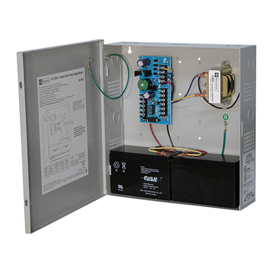
The AL175ULX is a power-limited power supply/charger that will convert 115VAC / 60Hz input into two individually PTC
protected auto-resettable 12VDC or 24VDC outputs (see specifications). It is intended for use in applications requiring UL
Listing for Access Control System Units (UL 294) and applications requiring an interface with the Fire Alarm Control Panels.
Agency Listings:
• UL Listed for Access Control Systems (UL294).
CUL Listed - CSA Standard C22.2
No.205-M1983, Signal Equipment.
• MEA - NYC Dept. of Buildings Approved.
• CSFM - California State Fire Marshal Approved.
• Conforms to NFPA 101 life safety codes
Input:
• Input 115VAC / 60 Hz, 0.6A.
Output:
• Selectable 12VDC or 24VDC power-limited outputs.
• Class 2 Rated power-limited outputs.
• 1.75A continuous supply current @ 12VDC or 24VDC.
• Filtered and electronically regulated output.
• Short circuit and thermal overload protection.
Output VDC
Switch Position
12VDC
SW1 OFF
24VDC
SW1 ON
Stand-by Specifications:
Output
12VDC / 7 AH Battery
24VDC / 7 AH Battery
Wiring methods shall be in accordance with the National Electrical Code/NFPA 70/NFPA 72/ANSI, and with all local
codes and authorities having jurisdiction. Product is intended for indoor use only.
See Terminal Identification Chart on Pg. 3 for a description of each terminal function.
1. Mount unit in the desired location. Mark and predrill holes in the wall to line up with the top two keyholes in the
enclosure. Install two upper fasteners and screws in the wall with the screw heads protruding. Place the enclosure's
upper keyholes over the two upper screws; level and secure. Mark the position of the lower two holes. Remove the
enclosure. Drill the lower holes and install two fasteners. Place the enclosure's upper keyholes over the two upper
screws. Install the two lower screws and make sure to tighten all screws (Enclosure Dimensions, pg. 3).
Secure enclosure to earth ground.
2. Connect AC power to the black and white flying leads of the transformer. Secure green wire lead to earth ground.
Use 18 AWG or larger for all power connections (Battery, DC output). Use 22 AWG to 18 AWG for power-
limited circuits (trigger inputs, dry outputs).
Keep power-limited wiring separate from non power-limited wiring (115VAC / 60Hz Input, Battery Wires).
Minimum 0.25" spacing must be provided.
CAUTION: Do not touch exposed metal parts. Shut branch circuit power before installing or servicing equipment.
There are no user serviceable parts inside. Refer installation and servicing to qualified service personnel.
3. Set the AL175ULX to the desired DC output voltage by setting switch SW1 to the appropriate position (refer to
Power Supply Output Specification Table).
4. Measure output voltage before connecting devices. This helps avoiding potential damage.
AL175ULX
AL175ULX
Access Control Power Supply/Charger
Overview:
Specifications:
.
Power Supply Output Specifications:
Max. Stand-by Load DC
1.75A
1.75A
4 hr. of Stand-by and 5 Minutes of Alarm
Stand-by = 1.25A
Alarm = 1.25A
Installation Instructions:
Available from A1 Security Cameras
www.a1securitycameras.com email: sales@a1securitycameras.com
Battery Backup:
• Maximum charge current: 400mA.
• Automatic switch over to stand-by battery when AC fails.
Supervision:
• AC fail supervision (form "C" contacts).
• Dry trigger output (form "C" contacts).
Altronix Corp.
140 58th St. Brooklyn, NY
Fire Alarm Interface:
• Dry trigger input.
Visual Indicators:
• AC input and DC output LED indicators.
Added Features:
• Includes power supply, transformer, and enclosure.
Enclosure Dimensions:
13.5" x 13" x 3.25" (342.9mm x 330.2mm x 82.55mm).
Max. Alarm Load DC
1.75A
1.75A
Battery (optional)
12VDC
24VDC
- 1
Advertisement
Table of Contents

Related Manuals for Altronix AL175ULX


Summary of Contents for Altronix AL175ULX
- Page 1 There are no user serviceable parts inside. Refer installation and servicing to qualified service personnel. 3. Set the AL175ULX to the desired DC output voltage by setting switch SW1 to the appropriate position (refer to Power Supply Output Specification Table).
- Page 2 Stand-by Battery Stand-by Battery CAUTION: Optional rechargeable stand-by batteries must match the power supply output voltage setting. Keep power-limited wiring separate from non power-limited. Use minimum 0.25" spacing. - 2 - AL175ULX Available from A1 Security Cameras www.a1securitycameras.com email: sales@a1securitycameras.com...
- Page 3 These input terminals are designed to connect to the normally closed outputs of an access control or TRG1 and TRG2 fire alarm relay. These terminals control [LOCK+], and [STRIKE+], as well as AL175ULX output relay contacts [NC, NO, C] This terminal provides DC output voltage when [TRG1] and [TRG2] are shorted together and are LOCK+ typically used to power Mag Locks.
- Page 4 TRG1 TRG2 Altronix is not responsible for any typographical errors. Product specifications are subject to change without notice. 140 58th Street, Brooklyn, New York 11220 USA | phone: 718-567-8181 | fax: 718-567-9056 web site: www.altronix.com | e-mail: info@altronix.com | Lifetime Warranty | Made in U.S.A.
Need help?
Do you have a question about the AL175ULX and is the answer not in the manual?
Questions and answers