Advertisement
AL175ULB is a power-limited power supply/charger that converts a 28VAC input into two (2) individual PTC protected
12VDC or 24VDC outputs (see specifications). They are intended for use in applications requiring UL Listing for Access
Control (UL 294) and applications requiring an interface with Fire Alarm Control Panels.
Agency Listings:
• UL Recognized component for
Access Control Systems (UL 294).
Input:
• Input 28VAC, 56VA.
• Fire Alarm Panel or Access Control trigger input.
Output:
• 12VDC or 24VDC selectable outputs.
• 1.75A supply current.
• Two (2) Class 2 Rated power-limited outputs.
- Fail-Safe/Fail-Secure lock output (switched).
- Auxiliary power output (unswitched).
• PTC protected outputs, rated @ 2.5A.
• Filtered and electronically regulated output.
• Short circuit and thermal overload protection.
Output VDC
Switch Position
12VDC
SW1 OFF
24VDC
SW1 ON
Stand-by Specifications:
Output
12VDC / 7AH Battery
24VDC / 7AH Battery
The AL175ULB should be installed in accordance with article 760 of The National Electrical Code or NFPA 72 as well as
all applicable Local Codes.
See Terminal Identification Chart on page 3 for a description of each terminal function.
1. Mount the AL175ULB in the desired location/enclosure.
2. Connect 28VAC, 56VA transformer to the terminals marked [AC, AC].
Use 18 AWG or larger for all power connections (Battery, DC output).
Use 22 AWG to 18 AWG for power-limited circuits (trigger inputs, dry outputs).
Keep power-limited wiring separate from non power-limited wiring (115VAC / 60Hz Input, Battery Wires).
Minimum 0.25" spacing must be provided.
3. Set the AL175ULB to the desired DC output voltage by setting switch SW1 to the appropriate position
(see Power Supply Output Specification Chart, pg. 1).
4. Measure output voltage before connecting devices. This helps avoiding potential damage.
5. Connect battery to the terminals marked [+ BAT -] on the unit (battery leads included). Use two (2) 12VDC batteries
connected in series for 24VDC operation.
Note: For Access Control applications batteries are optional. When batteries are not used, a loss of AC will result in
the loss of output voltage. When the use of stand-by batteries is desired, they must be lead acid or gel type.
6. Connect appropriate signaling notification devices to AC Fail supervisory relay outputs.
Note: To meet UL requirements, AC Supervisory outputs must be connected to the zone of Alarm Control Panel
or to visual AC trouble indicator.
7. For Access Control Device & Fire Alarm Interface connections see Application Diagrams, pg. 4
and Terminal Identification Chart, pg. 3.
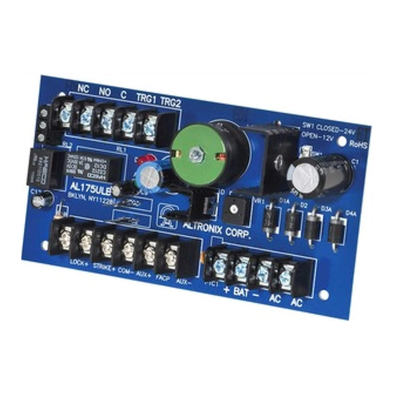
AL175ULB
Access Control Power Supply/Charger
Specifications:
Power Supply Output Specifications:
Max. Stand-by Load DC
1.75A
1.75A
4 hr. of Stand-by & 5 Minutes of Alarm
Stand-by = 1.25A
Alarm = 1.25A
Installation Instructions:
Overview:
Battery Backup:
• Built-in charger for sealed lead acid or gel type batteries.
• Automatic switch over to stand-by battery when AC fails.
• Maximum charge current 0.4A.
Supervision:
• AC fail supervision (form "C" contacts).
• Supervised Fire Alarm Disconnect
(Latching w/reset or Non-Latching).
Visual Indicators:
• AC input and DC output LED indicators.
Board Dimensions (W x L x H approximate):
3.1" x 5.8" x 1.5" (78.74mm x 147.32mm x 38.1mm).
Max. Alarm Load DC
1.75A
1.75A
Battery (optional)
12VDC
24VDC
Advertisement
Table of Contents

Related Manuals for Altronix AL175ULB


Summary of Contents for Altronix AL175ULB
-
Page 1: Specifications
24VDC / 7AH Battery Installation Instructions: The AL175ULB should be installed in accordance with article 760 of The National Electrical Code or NFPA 72 as well as all applicable Local Codes. See Terminal Identification Chart on page 3 for a description of each terminal function. - Page 2 Note: Expected battery life is 5 years; however, it is recommended changing batteries in 4 years or less if needed. SW1 OFF - 12V, ON - 24V TRG1 TRG2 LOCK + STRIKE + COM - AUX + FACP AUX - + BAT -- - 2 - AL175ULB...
-
Page 3: Terminal Identification
These input terminals are designed to connect to the normally closed outputs of an access control or TRG1 & TRG2 fire alarm relay. These terminals control [LOCK+], and [STRIKE+], as well as AL175ULB output relay contacts [N.C., N.O., C] This terminal provides DC output voltage when [TRG1] and [TRG2] are shorted together and are LOCK + typically used to power Mag Locks. - Page 4 Fig. 6 - Multiple AL175UL(X) power supply connections: Altronix is not responsible for any typographical errors. 140 58th Street, Brooklyn, New York 11220 USA, 718-567-8181, fax: 718-567-9056 website: www.altronix.com, e-mail: info@altronix.com. Lifetime Warranty, Made in U.S.A. MEMBER IIAL175ULB - Rev. 081601...
Need help?
Do you have a question about the AL175ULB and is the answer not in the manual?
Questions and answers