Advertisement
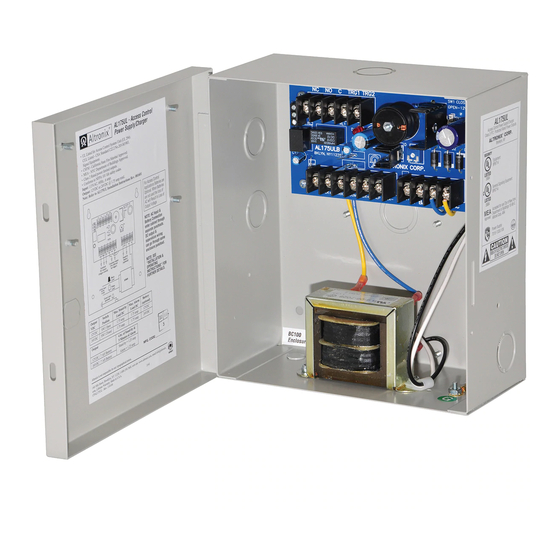
AL175UL is a power-limited power supply/charger that converts 115VAC / 60Hz input into two individually PTC pro-
tected 12VDC or 24VDC outputs (see specifications). It is intended for use in applications requiring UL Listing for Access
Control (UL294) and applications requiring an interface with the Fire Alarm Control Panels. It must be installed in accor-
dance with National and Local Electrical Codes and Regulations.
Agency Listings:
Input:
Output:
Power Supply Output Specifications:
Output
Switch Position
VDC
12VDC
24VDC
Stand-by Specifications:
Output
The AL175UL should be installed in accordance with article 760 of The National Electrical Code or NFPA 72 as well as
all applicable Local Codes.
See Terminal Identification Chart on page 3 for a description of each terminal function.
1. Mount the unit in the desired location. Mark and predrill holes in the wall to line up with the top two keyholes in the
enclosure. Install two upper fasteners and screws in the wall with the screw heads protruding. Place the enclosure's
upper keyholes over the two upper screws, level and secure. Mark the position of the lower two holes. Remove the
enclosure. Drill the lower holes and install the two fasteners. Place the enclosure's upper keyholes over the two upper
screws. Install the two lower screws and make sure to tighten all screws (Enclosure Dimensions, pg. 3).
power-limited circuits (trigger inputs, dry outputs).
Keep power-limited wiring separate from non power-limited wiring (115VAC / 60Hz Input, Battery Wires).
Minimum 0.25" spacing must be provided.
CAUTION: Do not touch exposed metal parts. Shut branch circuit power before installing or servicing equipment.
There are no user serviceable parts inside. Refer installation and servicing to qualified service personnel.
(Power Supply Output Specification Table).
4. Measure output voltage before connecting devices. This helps avoiding potential damage.
AL175UL
All manuals and user guides at all-guides.com
AL175UL
Access Control Power Supply/Charger
Specifications:
Max. Stand-by
Load DC
1.75 amp
1.75 amp
4 hr. of Stand-by & 5 Minutes of Alarm
Installation Instructions:
Overview:
Output (cont'd.):
Battery Backup:
Altronix Corp.
140 58th St. Brooklyn, NY
Supervision:
Enclosure Dimensions:
Max. Alarm
Battery
Load DC
(optional)
1.75 amp
12VDC
1.75 amp
24VDC
- 1 -
Advertisement
Table of Contents

Related Manuals for Altronix AL175UL


Summary of Contents for Altronix AL175UL
- Page 1 4 hr. of Stand-by & 5 Minutes of Alarm Installation Instructions: The AL175UL should be installed in accordance with article 760 of The National Electrical Code or NFPA 72 as well as all applicable Local Codes. See Terminal Identification Chart on page 3 for a description of each terminal function.
- Page 2 AUX + FACP AUX -- + BAT -- Con tant output Switched Stand-by (Not affected Battery DC output by trigger) (optional) (trigger control) Black Lead 115VAC input 60 Hz, XFMR White .6 amp Lead Green Lead (ground) - 2 - AL175UL...
- Page 3 (15.24mm) (15.24mm) (31.75mm) (153.67mm) 1.125” 1.125” (28.575mm) (28.575mm) 2” (50.8mm) 2” (50.8mm) 8.125” (206.375mm) 1” 1” (25.4mm) (25.4mm) 6.05” 0.6” 0.6” 1.25” (153.67mm) (15.24mm) (15.24mm) (31.75mm) 3.5” (88.9mm) 1” (25.4mm) 1” 5.25” 1” (25.4mm) (133.35mm) (25.4mm) AL175UL - 3 -...
- Page 4 Fig. 3 - Typical dual mag lock installation with fire alarm COM -- FACP ACCESS CONTROL TRG2 DEVICE TRG1 NO RESET SWITCH MAG LOCK LOCK + STRIKE + Fig. 6 - Multiple AL175UL(X) power supply MAG LOCK COM -- FACP TRG2 TRG1 TRG1 TRG2 MEMBER - 4 - AL175UL...
Need help?
Do you have a question about the AL175UL and is the answer not in the manual?
Questions and answers