Table of Contents
Advertisement
Available languages
Available languages
Quick Links
BOULONNEUSE TIREFONNEUSE ELECTRIQUE A PERCUSSIONS
ELEKTRO-SCHLAGSCHRAUBER
ATORNILLADOR ELECTRICO DE IMPACTO
AVVITATORE ELETTRICO AD IMPULSI
OPERATION AND MAINTENANCE MANUAL
NOTICE D'UTILISATION ET ENTRETIEN
BEDIENUNGSANLEITUNG
MANUAL DE USO Y MANTENIMIENTO
MANUALE D'USO E MANUTENZIONE
1
ELECTRIC IMPACT WRENCH
NR-13E
NR-13E-110
09 M 079
ENGLISH
FRANÇAIS
DEUTSCH
ESPAÑOL
ITALIANO
Advertisement
Table of Contents

Related Manuals for Cembre NR-13E


Summary of Contents for Cembre NR-13E
- Page 1 DEUTSCH ESPAÑOL ITALIANO ELECTRIC IMPACT WRENCH BOULONNEUSE TIREFONNEUSE ELECTRIQUE A PERCUSSIONS ELEKTRO-SCHLAGSCHRAUBER ATORNILLADOR ELECTRICO DE IMPACTO AVVITATORE ELETTRICO AD IMPULSI NR-13E NR-13E-110 OPERATION AND MAINTENANCE MANUAL NOTICE D'UTILISATION ET ENTRETIEN BEDIENUNGSANLEITUNG MANUAL DE USO Y MANTENIMIENTO MANUALE D'USO E MANUTENZIONE...
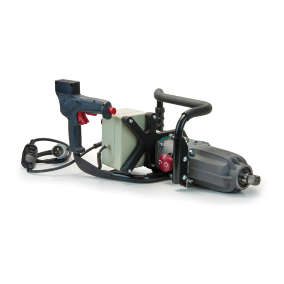
- Page 2 FIG. 1...
-
Page 3: Risk Of Hearing Damage
ENGLISH ATTENTION! – Before using the machine, carefully read the instructions contained in this manual. SAVE THESE INSTRUCTIONS: this manual contains important safety and operating instructions for the impact wrench. – Always wear hearing protection. RISK OF HEARING DAMAGE Under normal operating conditions, this machine may cause the operator to be exposed to a personal and daily noise level of over 85 db (A). -
Page 4: General Characteristics
ENGLISH 1. GENERAL CHARACTERISTICS NR-13E NR-13E-110 IMPACT WRENCH TYPE: Application range: suitable for tightening and loosening operations using an impact system, for railway and industrial applications. Capacity: (max. bolt diameter) 33 mm 2500 Nm (1844 ft.lbs) Max. torque developed: single-phase... - Page 5 The extension cable must be fully extended and not exceed 15m (50ft) in length. In order to safely provide the maximum output, the extension cable must have 3 conductors, each at least: - 3x1,5 mm (3x16 AWG) for the NR-13E - 3x2,5 mm (3x13 AWG) for the NR-13E-110...
- Page 6 ENGLISH 3. INSTRUCTIONS FOR USE 3.1) Control grip FIG. 2 The control grip has been designed to provide easy and comfortable access to the operating buttons both in vertical and horizontal positions (Ref. to fig. 8, 9). Refer to fig. 2 and operate as follows: Horizontal use - Hold the control grip so as to use SAFETY INTERLOCK (15H) and OPERATING BUTTON (02H).
- Page 7 ENGLISH 3.3) Torque adjustment (Ref. to Fig. 3) The wrench is equipped with a system which allows torque limitation on tightening and loosening. For particular requirements it is possible to vary the torque by means of a 5 position selector (15). To select different torque values, simply turn the selector in one di- rection or the other.
- Page 8 – On finishing the operation, release the button. The impact wrench can be used independently or in conjuntion with the Cembre support trolley (Ref. to Figs. 10, 11) and appropriate interface device (see § 6).
-
Page 9: Extraordinary Maintenance
ENGLISH 4. MAINTENANCE Always disconnect the power supply before any maintenance operation on the machine. Never open the electrical control box when the machine is connected to the mains supply. 4.1) ORDINARY MAINTENANCE Avoid placing the wrench on dusty or muddy ground. After each day’s use, carefully clean the wrench with a cloth making sure to remove any dirt it has picked up, paying particular attention to moving parts and the anvil zone. -
Page 10: Troubleshooting Guide
ENGLISH 4.2.4) Changing the motor brushes (See Fig. 13) After disconnecting the electric plug, check the degree of wear of the brushes; if necessary replace them as follows: – Using a 4 mm Allen wrench, remove the screws holding the two motor covers. –... - Page 11 57 and 67 mm (2.25 and 2.64 in.). – Plastic case type “VAL P20” code 2874155 for storing the accessories. – Steel case type “VAL-NR-13E” code 2874151 for storing the wrench and accessories case VAL P20.
- Page 12 – Support trolley type CS-SD and CS-SD-E NOTE: Fit the 10 cm socket extension when using the wrench on support trolley. Contact Cembre for further information. Check that the trolley is fitted with a gas spring calibrated at 1500 N rather than 1900 N.
- Page 13 FRANÇAIS RECOMMANDATIONS ! – Avant d'utiliser la machine, lire attentivement les instructions de cette notice. CONSERVEZ CES INSTRUCTIONS: cette notice contient d'impor- tantes instructions relatives à la sécurité et au fonctionnement de la machine. – Porter toujours un casque de protection auditive. RISQUE DE DOMMAGE AUDITIF.
-
Page 14: Caracteristiques Generales
FRANÇAIS 1. CARACTERISTIQUES GENERALES NR-13E NR-13E-110 BOULLONEUSE TYPE: Domaine d’application: conçue pour les opérations de vissage/dévissage par un système à percussions dans des applications ferroviaires et industrielles 33 mm Capacité: (ø boulon maxi.) 2500 Nm (1844 ft.lbs) Couple maxi. développé: monophasé... - Page 15 à la terre. Afin de garantir le débit de puissance maximum, la rallonge doit être complè- tement déployée, doit ne pas excéder une longueur de 15 mètres et avoir une section minimum de: - 3x1,5 mm pour la boulloneuse NR-13E - 3x2,5 mm pour la boulloneuse NR-13E-110...
-
Page 16: Instructions D'utilisation
FRANÇAIS 3. INSTRUCTIONS D’UTILISATION 3.1) Poignée de commande FIG. 2 La poignée de commande double a été spécialement étudiée afin de permettre une utilisation pratique et confortable de la boulonneuse, tant en position verticale que horizontale (Voir fig. 8 et 9). Pour une utilisation en position hori- zontale - Prendre la poignée de façon à... - Page 17 FRANÇAIS 3.3) Réglage du couple (Voir Fig. 3) La machine est dotée d’un système qui permet de limiter le couple lors des opérations de vissage ou de dévissage. En cas de besoin particulier, il est possible de varier le couple à l’aide du sélecteur (15) à...
- Page 18 – À la fin de l’opération, lâcher le bouton poussoir. En l’occurrence, il est possible de travailler sur le chariot support de Cembre (voir Fig. 10, 11); il suffit d’acquérir séparément le chariot support avec le dispositif d’assemblage correspondant (voir § 6).
-
Page 19: Entretien Courant
FRANÇAIS 4. ENTRETIEN Avant d'accomplir des opérations d'entretien, arrêter le moteur et débrancher la prise de l’alimentation électrique. N'ouvrir en aucun cas le boîtier électrique et n’effectuer aucune opération d’entretien si le câble d’alimentation est branché à une prise électrique. 4.1) ENTRETIEN COURANT Eviter de poser la machine directement sur des terrains poussiéreux ou boueux. -
Page 20: Anomalies Possibles
FRANÇAIS 4.2.4) Changement des balais (Voir Fig. 13) Après avoir débranché la prise secteur contrôler l’état d’usure des balais; si leur remplacement est nécessaire procéder comme suit: – A l’aide d’une clé Allen de 4 mm dévisser les vis et enlever les deux protections latérales du moteur. –... -
Page 21: Accessoires En Option
Pour la fixation des douilles avec diamètre de gorge compris entre 57 et 67 mm. – Malette “VAL P20” code 2874155 Pour ranger les divers accessoires. – Coffret type “VAL-NR-13E” code 2874151 Robuste coffret métallique pour ranger la machine et la malette VAL P20. - Page 22 NOTE: Pour l’emploi de la tirefonneuse avec le chariot, l’utilisation de la rallonge de 10 cm est conseillé. Contacter Cembre pour tout Vérifiez que le chariot soit renseignement complémentaire. équipé du vérin à gaz taré à 1.500N au lieu de 1900N.
- Page 23 DEUTSCH ACHTUNG! – Vor Inbetriebnahme unbedingt die Bedienungsanleitungen durchlesen. BEWAHREN SIE DIESE HINWEISE AUF! Diese Bedienungsanleitung enthält wichtige Sicherheits- und Gebrauchsanweisungen für die Bohrmaschine. – Tragen Sie stets einen Gehörschutz! ES BESTEHT DIE GEFAHR VON GEHÖRSCHÄDEN! Unter normalen Gebrauchsbedingungen kann der zuständige Bediener dieser Maschine einer täglichen Lärmbelastung von 85db (A) und mehr ausgesetzt sein.
-
Page 24: Allgemeine Eigenschaften
DEUTSCH 1. ALLGEMEINE EIGENSCHAFTEN NR-13E NR-13E-110 SCHLAGSCHRAUBER TYP: Anwendungsbereich: geeignet zum Lösen und Anziehen von Muttern mit Schlagwerk im Eisenbahn- und Industriebereich Leistungen: 33 mm (Max. Schraubendurchmesser) 2500 Nm (1844 ft.lbs) Max. Drehmoment: Einphasen Elektromotor: 220 - 230 V / 50 - 60 Hz... - Page 25 Bei Bedarf kann ein Verlängerungskabel mit einer maximalen Länge von 15 m verwendet werden. Das Verlängerungskabel muss vollständig ausgerollt werden, in einem einwand- freiem Zustand sein und mit angeschlossenem Schutzleiter. Mindestquerschnitt: - 3x1,5 mm für Schlagschrauber NR-13E - 3x2,5 mm für Schlagschrauber NR-13E-110...
- Page 26 DEUTSCH 3. BEDIENUNGSHINWEISE 3.1) Funktionsgriff BILD 2 Der Griff ist mit zwei Funktionen ausge- stattet, so dass ein einfaches Bedienen in waagerechter und senkrechter Position möglich ist (siehe Bild 8, 9). Für die Bedienung Bild 2 beachten! Bei waagerechter Benutzung - den Si- cherheitshebel (15H) drücken und gleich- zeitig den Startknopf (02H) betätigen.
- Page 27 DEUTSCH 3.3) Einstellung des Drehmoments (Siehe Bild 3) Der Schlagschrauber ist mit einem System ausgerüstet, dass die Regulierung des Drehmomentes beim Lösen oder Anziehen der Muttern ermöglicht. Bei Bedarf kann das Drehmoment mit der Drehmoment-eneinstellung (15) in 5 verschiedene Positionen gestellt werden. Zum Einstellen kann der Schalter in beide Richtungen gedreht werden.
- Page 28 – Das Kabel vor heißem Öl und scharfen Gegenständen schützen! 3.8) Schmelzsicherung (Siehe Bild 6) Die Maschine verfügt über eine Sicherung (14) für den Motor: NR-13E: 16A (6,3X32) VERZÖGERTE SCHMELZSICHERUNG NR-13E-110: 30A (6,3X32) VERZÖGERTE SCHMELZSICHERUNG Beim Austausch nur Sicherungen mit den gleichen Parametern verwenden.
-
Page 29: Ausserordentliche Wartung
DEUTSCH 4. WARTUNG Bei Reparaturen oder Wartung an der Maschine unbedingt den Netzstecker ziehen. Auf keinen Fall den elektrischen Schaltkasten öffnen oder Wartungsarbeiten ausführen, wenn die Maschine unter Spannung steht bzw. der Netzstecker an einer Stromversorgung angeschlossen ist. 4.1) ORDENTLICHE WARTUNG Vermeiden Sie es, den Schrauber direkt auf staubigen oder schlammigen Boden zu stellen. -
Page 30: Problemlösung
DEUTSCH 4.2.4) Kontrolle der Kohlebürsten und eventueller Wechsel (Siehe Bild 13) Den Netzstecker ziehen und die Kohlebürsten kontrollieren und bei Bedarf folgendermaßen tauschen: – Mit einem 4 mm Imbusschlüssel lösen Sie die Schrauben an den Abdeckungen des Motors. – Mit einem 3 mm Imbusschlüssel lösen Sie die Schrauben (V) los und entfernen die Kohlebürs- tenfedern und die Kohlebürsten (S). -
Page 31: Zubehör Auf Anfrage
Für die Arretierung der Steckschlüssel mit einem Nut Durchmesser von 57 und 67 mm. – Kunststoffkoffer Typ “VAL P20” Bestell Nr. 2874155 Zur Aufbewahrung des Zubehörs. – Metallkoffer Typ “VAL-NR-13E“ Bestell Nr. 2874151 Zur Aufbewahrung und Transport von Schlagschrauber und Kunststoffkoffer VAL P20. - Page 32 Bei Verwendung des Schlagschraubers mit dem Stützwagen ist eine 10 cm Verlängerung einzusetzen. Für weitere Informationen, Immer berücksichtigen, dass die bitte mit Cembre Kontakt Gasfeder auf dem Stützwagen aufnehmen. auf 1500 N anstatt 1900 N eingestellt ist. – Abdeckung TARPCOVER 027-NR Bestell Nr.
- Page 33 ESPAÑOL ¡ATENCION! – Antes de utilizar la máquina leer atentamente las instrucciones conte nidas en este manual. GUARDE ESTAS INSTRUCCIONES: este manual contiene instrucciones de seguridad y funcionamiento importantes para la taladradora. – Ponerse siempre cascos de protección para el oído. RIESGO DE DAÑO AUDITIVO.
-
Page 34: Características Generales
ESPAÑOL 1. CARACTERÍSTICAS GENERALES NR-13E NR-13E-110 ATORNILLADOR TIPO: Campo de aplicación: adecuado para operaciones de atornillado/destornillado por medio de un sistema a impulsos, en aplicaciones ferroviarias e industriales Capacidad: (ø max. bulón) 33 mm Par de torsión máx desarrollado: 2500 Nm (1844 ft.lbs) Motor eléctrico:... - Page 35 Para asegurar la entrega de potencia máxima, el cable de prolongación debe ser completamente exendido, tener una longitud máxima de 15 metros y una sección mayor o igual a: - 3x1,5 mm para el atornillador NR-13E - 3x2,5 mm para el atornillador NR-13E-110...
-
Page 36: Instrucciones De Uso
ESPAÑOL 3. INSTRUCCIONES DE USO 3.1) Empuñadura de mandos FIG. 2 La empuñadura que reúne los mandos ha sido estudiada para permitir un uso ágil y cómodo del atornillador tanto en posición horizontal como en posición vertical (ver Fig. 8 y 9). Por tanto, con referencia a la Fig. - Page 37 ESPAÑOL 3.3) Regulación del par de torsión (Ref. a Fig. 3) El atornillador está dotado de un sistema que permite limitar el par de torsión al atornillar o destornillar. Para exigencias especiales, es posible variar el par de torsión por medio del selector (15) que se puede accionar sobre 5 posiciones diferentes.
- Page 38 – Al final de la operación soltar el botón. Si es necesario el atornillador puede ser utilizado con el carro de soporte Cembre (Ref. a Fig. 10, 11) pidiendo éste por separado con el correspondiente dispositivo de interconexión (ver § 6).
-
Page 39: Mantenimiento Ordinario
ESPAÑOL 4. MANTENIMIENTO Antes de efectuar las operaciones de mantenimiento o abrir el cuadro eléctrico, desconectar el enchufe de la alimentación eléctrica. 4.1) MANTENIMIENTO ORDINARIO Evitar apoyar el atornillador directamente sobre terrenos polvorientos o fangosos. Después de cada día de uso, limpiar con cuidado el atornillador con un trapo limpio, teniendo cuidado de eliminar la suciedad que se ha depositado sobre él, especialmente cerca de las partes móviles como la zona del bloque de impacto. -
Page 40: Solución De Los Problemas
ESPAÑOL 4.2.4) Cambio de los cepillos (Ref. a Fig. 13) Tras desconectar el enchufe de alimentación controlar el estado de desgaste de los cepillos; de ser necesario cambiarlos de la siguiente manera: – Con llave allen de 4 mm, quitar los tornillos y las dos protecciones del motor. –... -
Page 41: Accesorios Suministrados Bajo Demanda
Para la fijación de las llaves de vaso con diámetro entre la ranura de 57 a 67 mm. – Caja de plástico “VAL P20” código 2874155 Para guardar los diversos accesorios. – Caja tipo “VAL-NR-13E” código 2874151 Sólida caja metálica para guardar la máquina y la caja VAL P20. - Page 42 NOTA: Para la utilización del atorni- llador con el carro es recomendable el uso de una prolongación de 10 cm. Para más información contactar con Cembre. Verificar que el carro esté provis- to de pistón a gas calibrado a 1500N en vez de1900N.
- Page 43 ITALIANO ATTENZIONE – Prima di utilizzare questa macchina, leggere attentamente le istruzioni contenute in questo manuale. CONSERVARE QUESTE ISTRUZIONI: questo manuale contiene importanti istruzioni per la sicurezza ed il funzionamento dell’avvitatore. – Indossare sempre cuffie di protezione per l'udito. RISCHIO DI DANNO UDITIVO. Nelle normali condizioni di utilizzo, questa macchina può...
-
Page 44: Caratteristiche Generali
ITALIANO 1. CARATTERISTICHE GENERALI NR-13E NR-13E-110 AVVITATORE TIPO: Campo di applicazione: adatto per operazioni di avvitamento/svitamento tramite sistema ad impulsi, in applicazioni ferroviarie e industriali Prestazioni: (ø max. bullone) 33 mm Coppia max. sviluppata: 2500 Nm (1844 ft.lbs) monofase Motore elettrico:... - Page 45 Per garantire l’erogazione della massima potenza, la prolunga deve essere completamente distesa, avere una lunghezza massima di 15 metri ed una sezione non inferiore a: - 3x1,5 mm per l’avvitatore NR-13E - 3x2,5 mm per l’avvitatore NR-13E-110...
-
Page 46: Istruzioni Per L'uso
ITALIANO 3. ISTRUZIONI PER L'USO 3.1) Manopola comandi FIG. 2 La manopola (01) è stata studiata per permettere un agevole e comodo utilizzo dell’avvitatore sia in posizione verticale che orizzontale (Rif. a Fig. 8, 9). A tale scopo, operare come segue: Utilizzo orizzontale - impugnare la ma- nopola in modo da premere la LEVA DI SICUREZZA (15H) e il PULSANTE (02H). - Page 47 ITALIANO 3.3) Regolazione della coppia (Rif. a Fig. 3) L'avvitatore é dotato di un sistema che permette di limitare la coppia in avvitamento o svitamento. In funzione delle esigenze é possibile variare la coppia tramite il selet- tore (15), regolabile su 5 diverse posizioni. Per selezionare i valori di coppia ruotare il selettore in un senso o nell'altro, impostando il valore desiderato.
- Page 48 All'occorrenza l'avvitatore può essere reso "carrellabile" (Rif. a Fig. 10, 11) richiedendo separatamente il carrello di supporto Cembre ed il relativo dispositivo di interfacciamento (vedi § 6). – Per l’utilizzo dell'avvitatore in posizione verticale con il carrello di supporto é necessario montare sull’avvitatore il dispositivo di interfacciamento tipo KCS-NR.
-
Page 49: Manutenzione Ordinaria
Le operazioni di manutenzione descritte ai § 4.2.1 e 4.2.2 richiedono l'intervento di personale qualificato, per questo consigliamo di contattare la Cembre. 4.2.3) Rabbocco o cambio dell’olio nel gruppo cambio-riduttore (ogni 4 anni) Per rabboccare o sostituire l'olio nel gruppo cambio-riduttore operare come segue: –... -
Page 50: Soluzione Dei Problemi
ITALIANO 4.2.4) Cambio delle spazzole del motore (Rif. a Fig. 13) Dopo aver scollegato la spina di alimentazione controllare lo stato di usura delle spazzole; se ne- cessario procedere alla sostituzione operando come segue: – Con chiave a brugola da 4 mm svitare le viti e togliere le due protezioni laterali del motore. –... -
Page 51: Accessori Fornibili A Richiesta
57 e 67 mm. – Valigetta “VAL P20” cod. 2874155 in materiale plastico, adatta al contenimento degli accessori. – Cassetta tipo “VAL-NR-13E ” cod. 2874151 Robusta cassa per il trasporto e il contenimento dell’avvitatore e della valigetta VAL P20. - Page 52 – Carrello di supporto tipo “CS-SD”. NOTA: Per l’utilizzo dell’avvitatore con il carrello é consigliabile l’uso di una prolunga da 10 cm. Contattare la Cembre per ulteriori informazioni a riguardo. Verificare che il carrello sia provvisto di molla a gas tarata a 1500N anziché...
- Page 53 “CLIP” Socket wrench Douille Steckschlüssel Llave de vaso Chiave a bussola “CLIP” “CLIP” Push here Presser ici Hier drücken Empujar aqui Spingere qui...
- Page 54 FIG. 8 FIG. 9 - Horizontal position - Position horizontale - Waagrechte Position - Posición horizontal - Posizione orizzontale Vertical position - Position verticale - Senkrechte Position - Posición vertical Posizione verticale FIG. 10 Socket extension Rallonge Verlängerung Prolongación Prolunga Support trolley Chariot support Stützwagen...
- Page 55 FIG. 11 Support trolley Chariot support Stützwagen Carro de soporte KHOR-NR Carrello di supporto Max. oil level Niveau maxi. d’huile Max. Ölstand Nivel de aceite máx. Livello max. olio FIG. 12a FIG. 12 FIG. 13...
- Page 56 Centre; if possible, attach a copy of the Test Certificate supplied by Cembre together with the tool or fill in and attach the form available in the “ASSISTANCE” section of the Cembre website.
-
Page 58: User Information
– Following information applies in member states of the European Union: – Les informations suivantes sont destinées aux pays membres de l’Union Européenne: – Die folgenden Hinweise gelten für Mitglieder der Europäischen Union: – Las siguientes informaciones conciernen a los estados miembros de la Unión Europea: –... -
Page 59: Informazione Agli Utenti
Deutsch ----------------------------------------------------------------------------------------------- INFORMATION FÜR DEN BENUTZER gemäß der “Richtlinien 2011/65/EU und 2012/19/EU in Bezug auf den reduzierten Gebrauch von gefährlichen Substanzen in elektrischen und elektroni- schen Geräten, sowie auf die Abfallentsorgung”. Das durchkreuzte Zeichen auf dem Mülleimer, welches auf dem Gerät oder seiner Verpackung ange- bracht ist, zeigt an, dass das Produkt am Ende seiner Lebenszeit getrennt von den anderen Abfällen entsorgt werden muss. - Page 60 Déclarons sous notre seule responsabilité que le produit Erklären in alleiniger Verantwortung daß das Produkt Declaramos bajo nuestra responsabilidad que el producto Dichiariamo sotto nostra unica responsabilità che il prodotto NR-13E ; NR-13E-110 ..........................................(type) (type) (Typ) (tipo) (tipo) ..........................................
Need help?
Do you have a question about the NR-13E and is the answer not in the manual?
Questions and answers