Table of Contents
Advertisement
Quick Links
Advertisement
Table of Contents

Related Manuals for FIFOTRACK A100


Summary of Contents for FIFOTRACK A100
- Page 1 FIFOTRACK VEHICLE GPS TRACKER Model: A100 Version: V1.1 www.fifotrack.com...
- Page 2 A100 USER GUIDE Copyright and Disclaimer All copyrights belong to Shenzhen fifotrack Solution Co., Ltd. You are not allowed to revise, copy or spread this file in any form without consent of fifotrack. is trademark of fifotrack, protected by law.
-
Page 3: Table Of Contents
9.1 I/O Installation ....................... 14 9.2 Power/Ground Cable ..................... 15 9.3 Positive/Negative Digital Input(IN1/IN2/IN3) ............15 9.4 Analog Input( AD) ......................15 9.5 Output control (out1/out2) ................... 16 9.6 Installing Microphone or Speaker (Optional) ..............16 Copyright © fifotrack 2015 All rights reserved... -
Page 4: Product Overview
It can integrate with different sensors and collect the specific data as per customers’ requirements. Besides, A100 has core functions to meet users’ demands, such as harsh acceleration/braking alarm, driving behavior analysis, custom digital input, jamming detection, two-way calling and OTA. -
Page 5: Other Functions
Mileage And Running Time Settings Voice monitoring (Optional) Two-way Calling (Optional) 3 Product and Accessories 3.1 Standard Packing Box Main Unit Wire GPS Antenna GSM Antenna 3.2 Optional Accessories USB Cable Relay Microphone Speaker Copyright © fifotrack 2015 All rights reserved... -
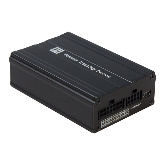
Page 6: Product Appearance
A100 USER GUIDE AS10 Fuel sensor 4 Product Appearance Copyright © fifotrack 2015 All rights reserved... -
Page 7: Pcb Overview And Hardware Design
Anti static: The vehicle product’s working condition is complex. It is very easy to be influenced by static, which causes damage to the product’s peripheral interfaces. Through ESD protection on Copyright © fifotrack 2015 All rights reserved... -
Page 8: Led Light
Operating -20℃~70℃ Temperature Humidity 5%~95% LED Light 3 LED lights indicating GPS/GSM/External power status Button/ Switch 1 SOS Button, 1 power switch Flash Memory 8MB (GPRS data 16000 units, SMS data 4000 units) Copyright © fifotrack 2015 All rights reserved... -
Page 9: First Use
8 First Use 8.1 Charging First time use A100, please connect positive wire(+ Red) and ground wire(-black) to 12V or 24V external power supply, charging device at least 2 hours, 3 hours is suggested. Before installation, ensure all of the parameters setting and test are finished. -
Page 10: Installing Gsm/Gps Antenna
Don’t install the GPS antenna where shielded by metal. For example, inside a metal can. 8.4 Tracking by Calling Call the SIM card number inside A100, you will get a SMS reply with Google map link. Click it for Copyright © fifotrack 2015 All rights reserved... -
Page 11: Sms Reply Contents Example
A100 USER GUIDE specific map location. 8.5 SMS Reply Content Example 2015-09-04 07:44:28, 0km/h, Disconnect, A, EXPW:ON,http://maps.google.com/maps ?f=q&hl=en&q=loc:22.546510,114.079403 SMS Reply Format: Copyright © fifotrack 2015 All rights reserved... -
Page 12: Tracking By Sms Command - C01
8.6 Tracking by SMS Command - C01 SMS Command:000000,C01 SMS Reply: Current location Note:Default SMS password is “000000”, set new SMS password with B10 command. Please refer to <FIFOTRACK COMMAND LIST> for more details. Copyright © fifotrack 2015 All rights reserved... -
Page 13: Configuration By Pc
USB cable driver and install it before using parameter tool. Refer to <USB CABLE DRIVER INSTALLATION GUIDE> if need. Connect A100 to PC with USB cable. Run “fifotrack Parameter Tool” software which will identify port automatically and read all of the current parameters. -
Page 14: Device Installation
12 bits analog input, supports voltage range 0-12V. Connect to external sensor, eg,fuel sensor or temperature sensor. OUT1 Yellow Output1 Output active: low level (0V) Output inactive: open drain (OD) Max open-drain (inactive) voltage: 45V Copyright © fifotrack 2015 All rights reserved... -
Page 15: Power/Ground Cable
Output active: low level (0V) Output inactive: open drain (OD) Max open-drain (inactive) voltage: 45V Max current for output low voltage (valid): 500mA 9.2 Power/Ground Cable 9.3 Positive/Negative Digital Input (IN1/IN2/IN3) 9.4 Analog Input( AD) Calculation formula: Copyright © fifotrack 2015 All rights reserved... -
Page 16: Output Control (Out1/Out2)
Note:Original AD value is in hexadecimal. Convert it to decimal first, then use the formula. 9.5 Output control (OUT1/OUT2) 9.6 Installing Microphone or Speaker (Optional) Please e-mail us at info@fifotrack.com if any question or feedback. Copyright © fifotrack 2015 All rights reserved...
Need help?
Do you have a question about the A100 and is the answer not in the manual?
Questions and answers