Table of Contents
Advertisement
Quick Links
Advertisement
Table of Contents

Summary of Contents for FIFOTRACK A500
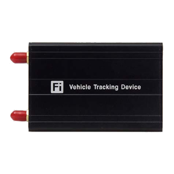
- Page 1 FIFOTRACK 3G VEHICLE GPS TRACKER Model: A500 Version: V1.1 www.fifotrack.com...
-
Page 2: Copyright And Disclaimer
A500 USER GUIDE Copyright and Disclaimer All copyrights belong to Shenzhen fifotrack Solution Co., Ltd. You are not allowed to revise, copy or spread this file in any form without consent of fifotrack. is trademark of fifotrack, protected by law. - Page 3 A500 USER GUIDE Related Files Version File Remarks V1.1 <fifotrack A500 GPRS Protocol and Command GPRS protocol between terminal List> and server, command details of GPRS/SMS/COM V1.1 <fifotrack Parameter Tool User Guide> PC software tool for parameters configuration V1.1 <USB Cable Driver Installation Guide>...
-
Page 4: Table Of Contents
9 Device Installation ......................... 15 9.1 I/O Installation ..........................15 9.2 Power/GND Cable ......................... 17 9.3 Positive/Negative Digital Input (IN1/IN2/IN3/IN4) ................ 18 9.4 Analog Input (AD) ......................... 18 9.5 Output control (OUT1/OUT2) ....................... 19 Copyright © fifotrack 2015 All rights reserved... -
Page 5: Product Overview
A500 to have powerful functions such as photographing, driver identification and management, impulse detection and temperature monitoring. Besides the advanced functions, A500 has full functions to cover the normal demands of vehicle tracking. Not only fuel monitoring, harsh acceleration/braking alarm, driving behavior analysis, but also has custom digital input, jamming detection, two-way calling and OTA function. -
Page 6: Other Functions
Temperature sensor (Optional) Voice monitoring (Optional) Two-way Calling(Optional) Impulse detection (Default speedometer detection) 3 Product and Accessories 3.1 Standard Packing Box Main Unit Wire GPS Antenna GSM Antenna Copyright © fifotrack 2015 All rights reserved... -
Page 7: Optional Accessories
A500 USER GUIDE 3.2 Optional Accessories USB Cable Relay Microphone Speaker AS10 Fuel Sensor Calibrator RFID reader TUB01 ultrasonic fuel Camera i-Button Reader LED for TUB01 sensor Fingerprint 4 Product Appearance Copyright © fifotrack 2015 All rights reserved... -
Page 8: Pcba Overview And Hardware Design
Our product supports voltage 11V-36V. When the external power supply is below 10.5V, with low voltage detection, it will be automatically cut. When external power supply is over 36V or has high voltage peak, the product will trigger high-voltage protection through Copyright © fifotrack 2015 All rights reserved... -
Page 9: Led Light
Flash 0.1s on and 3s off GSM available Flash every 0.1s Device is initialing Flash 2s on and 2s off No GSM External Power Light(Red) External power cut Flash every 0.1s External power low External power normal Copyright © fifotrack 2015 All rights reserved... -
Page 10: Specification
1 USB port 7.2 Working Frequency UMTS Frequency/MHz GSM Frequency/MHz A500 Type 1900 2100 1800 1900 Type-A ■ ■ ■ ■ ■ ■ Type-E ■ ■ ■ ■ Type-T ■ ■ ■ ■ ■ ■ Copyright © fifotrack 2015 All rights reserved... -
Page 11: First Use
8 First Use 8.1 Charging First time use A500, please connect positive wire(+ Red) and ground wire(-black) to 12V or 24V external power supply, charging device for at least 2 hours, 3 hours is suggested. Before installation, ensure all of the parameters setting and test are finished. -
Page 12: Installing Gsm/Gps Antenna
Don’t install the GPS antenna where shielded by metal. For example, inside a metal can. 8.4 Tracking by Calling Call the SIM card number inside A500, you will get a SMS reply with Google map link. Click it for specific map location. -
Page 13: Sms Reply Content Example
Google map link, latitude in the Google map link with latitude and om/maps front of longitude after ”Loc”. longitude, which can be opened directly ?f=q&hl=en&q=loc:2 Unit degree on smart phone. 2.546510,114.07940 Latitude=22.546510° Longitude=114.079403° Copyright © fifotrack 2015 All rights reserved... -
Page 14: Tracking By Sms Command - C01
Refer to <USB CABLE DRIVER INSTALLATION GUIDE> if need. Connect A500 to PC with USB cable. Run “fifotrack Parameter Tool” software which will identify port automatically and read all of the current parameters. -
Page 15: Platform Tracking
A500 USER GUIDE Please read <FIFOTRACK PARAMETER TOOL USER GUIDE> for more details. 8.8 Platform Tracking You can use SMS commands B00, B01, B02, B03 to set server IP, port, APN and GPRS uploading interval. You can also set those parameters via parameter tool software on PC. - Page 16 Max current for output low voltage (valid): 500mA Blue 12 bits analog input, supports voltage range 0-12V. Connect to external sensor, e.g., fuel sensor. Blue 12 bits analog input, supports voltage range 0-6V. Connect to external sensor, e.g., fuel sensor. Copyright © fifotrack 2015 All rights reserved...
-
Page 17: Power/Gnd Cable
MIC+ SPK+ MCU_RS232_RX MIC- SPK- Function DC5V RS232 port for camera/RFID Reader/Ultrasonic fuel sensor/fingerprint scanner or other RS232 interface devices. MCU_RS232_TX MCU_RS232_RX MIC+ Microphone port MIC- SPK+ Speaker port SPK- 9.2 Power/GND Cable Copyright © fifotrack 2015 All rights reserved... -
Page 18: Positive/Negative Digital Input (In1/In2/In3/In4)
A500 USER GUIDE 9.3 Positive/Negative Digital Input (IN1/IN2/IN3/IN4) 9.4 Analog Input (AD) A500 supports 2 AD input, whose voltage range: AD1: 0~6V AD2: 0~12V Calculation formula: AD1 Voltage=(AD1)*3300*2/4096 AD2 Voltage=(AD2)*3300*62/(4096*15) Note:Original AD value is in hexadecimal. Convert it to decimal first, and then use the formula. -
Page 19: Output Control (Out1/Out2)
A500 USER GUIDE 9.5 Output control (OUT1/OUT2) Please e-mail us at info@fifotrack.com if any question or feedback. Copyright © fifotrack 2015 All rights reserved...


Need help?
Do you have a question about the A500 and is the answer not in the manual?
Questions and answers