Table of Contents
Advertisement
Quick Links
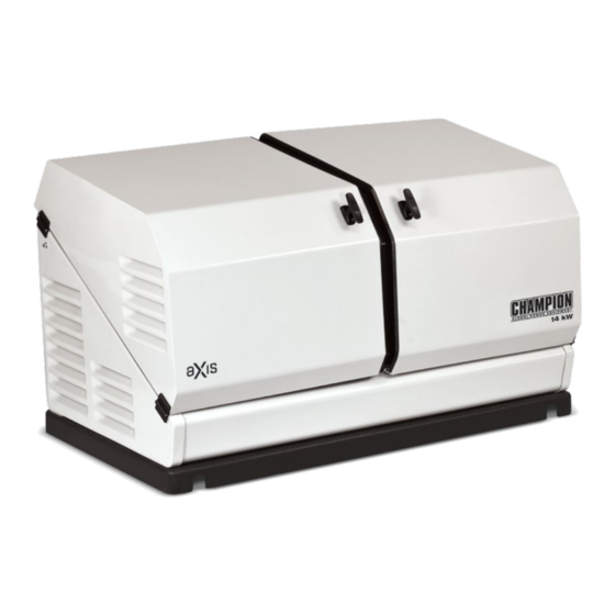
INSTALLATION MANUAL
aXis CONTROLLER HOME
STANDBY GENERATOR
All aXis Controller™ Models
REGISTER YOUR PRODUCT ONLINE
at championpowerequipment.com
4010077
or visit championpowerequipment.com
SAVE THESE INSTRUCTIONS. This manual contains important safety precautions which should be read and understood before operating the product. Failure to do
so could result in serious injury. This manual should remain with the product.
No part of this publication may be reproduced or used in any form by any means – graphic, electronic or mechanical, including photocopying, recording, taping or
information storage and retrieval systems – without the written permission of Champion Power Equipment (CPE).
REV 20201109
Champion Power Equipment, Inc., Santa Fe Springs, CA USA
Advertisement
Table of Contents

Subscribe to Our Youtube Channel
Related Manuals for Champion Global Power Equipment aXis


Summary of Contents for Champion Global Power Equipment aXis
- Page 1 INSTALLATION MANUAL aXis CONTROLLER HOME STANDBY GENERATOR All aXis Controller™ Models REGISTER YOUR PRODUCT ONLINE at championpowerequipment.com 4010077 or visit championpowerequipment.com SAVE THESE INSTRUCTIONS. This manual contains important safety precautions which should be read and understood before operating the product. Failure to do so could result in serious injury.
- Page 2 Have questions or need assistance? Do not return this product to the store! WE ARE HERE TO HELP! Visit our website: www.championpowerequipment.com for more info: – Product Info & Updates – Tech Bulletins – Frequently Asked Questions – Product Registration –...
-
Page 3: Table Of Contents
..........Checking Automatic Operation ........Installing Standby Generator to non-aXis Controller ™ ATS Safety Labels and Hang Tags ....... -
Page 4: Introduction
INTRODUCTION aXis CONTROLLER HOME STANDBY GENERATOR INTRODUCTION HOME STANDBY GENERATOR Congratulations on your purchase of a Champion Power Equipment This home standby generator is intended exclusively for outdoor installation. This generator will operate using either liquified (CPE) product. CPE designs, builds, and supports all of our products to strict specifications and guidelines. -
Page 5: Safety
SAfETY aXis CONTROLLER HOME STANDBY GENERATOR SAfETY Safety Definitions The purpose of safety symbols is to attract your attention to possible dangers. The safety symbols, and their explanations, deserve your careful attention and understanding. The safety warnings do not by themselves eliminate any danger. The instructions or warnings they give are not substitutes for proper accident prevention measures. -
Page 6: Safety Symbols
SAfETY aXis CONTROLLER HOME STANDBY GENERATOR Safety Symbols Some of the following symbols may be used on this product. Please study them and learn their meaning. Proper interpretation of these symbols will allow you to more safely operate the product. - Page 7 SAfETY aXis CONTROLLER HOME STANDBY GENERATOR SYMBOL MEANING Sever hazard (rotating blade) Crush hazard (top)
-
Page 8: Important Safety Instructions
IMPORTANT SAfETY INSTRUCTIONS aXis CONTROLLER HOME STANDBY GENERATOR IMPORTANT SAfETY INSTRUCTIONS Installation Hazards WARNING WARNING Have only a qualified electrician or installation technician who Cancer and Reproductive Harm – www.P65Warnings.ca.gov is familiar with applicable codes, standards and regulations install and service the generator. -
Page 9: Operation Hazards
Follow these steps in order: (CO) detector on each level of any building in operating condition. 1. Pull fuse from aXis Controller™ panel and secure with tape to the panel. Carbon Monoxide (CO) is a colorless, odorless, poisonous gas. -
Page 10: Electrical Shock Hazards
IMPORTANT SAfETY INSTRUCTIONS aXis CONTROLLER HOME STANDBY GENERATOR Electrical Shock Hazards Burn Hazards WARNING WARNING Use extreme caution when near the generator while it is DO NOT touch hot surfaces. operating. The generator produces dangerous voltage. – ALWAYS avoid contact with hot exhaust components and –... -
Page 11: Safety Labels And Hang Tags
SAfETY LABELS AND HANG TAGS aXis CONTROLLER HOME STANDBY GENERATOR SAfETY LABELS AND HANG TAGS WARNING DO NOT operate the generator if there are missing or badly worn safety labels. Safety labels must be legible to alert personnel of safety hazards. - Page 12 SAfETY LABELS AND HANG TAGS aXis CONTROLLER HOME STANDBY GENERATOR LABEL DESCRIPTION PART NO. DANGER CAUTION DANGER Explosion Hazard - Battery gases are explosive. Starting Hazard - The generator may crank and start any Read Operator’s Manual - Read, understand time without notice.
-
Page 13: Safety, Serial/Model, Nameplate Label Locations
SAfETY LABELS AND HANG TAGS aXis CONTROLLER HOME STANDBY GENERATOR Safety, Serial/Model, Nameplate Label Locations The safety labels have specific placement and must be replaced if they are unreadable, damaged or missing. a. Serial number location b. Nameplate c. NFPA 37 Compliance... -
Page 14: Specifications
SPECIfICATIONS aXis CONTROLLER HOME STANDBY GENERATOR SPECIfICATIONS 14kW HSB Specifications Home Standby Generator Maximum continuous power, LPG 14 kW Maximum continuous power, NG 12.5 kW Rated voltage 120/240 Amps 116.6/58.3 LPG (propane), 104/52 NG (natural gas) Harmonic distortion Less than 5%... -
Page 15: Champion 754Cc Engine
SPECIfICATIONS aXis CONTROLLER HOME STANDBY GENERATOR Champion 754cc Engine The 754cc engine was developed by Champion Engine Technology for use in Champion home standby generators. The V-Twin cylinder design provides high output, efficient operation, low maintenance and demonstrated long life. -
Page 16: Alternator Overview
UNPACkING aXis CONTROLLER HOME STANDBY GENERATOR UNPACkING Alternator Overview The alternator is made up with the following major components; WARNING 1. Brush holder assembly The HSB weighs more than 500 lbs. (227 kg). 2. Rear bearing carrier Use the aid of additional assistants and exercise caution during 3. -
Page 17: Installation
INSTALLATION aXis CONTROLLER HOME STANDBY GENERATOR INSTALLATION Placement & Installation Guidelines for Champion Home Standby Generators to Reduce the Risk of fire NATIONAL fIRE PROTECTION ASSOCIATION (NfPA) Annex A Explanatory Material STANDARD NfPA 37 REQUIREMENTS AND TESTING A.4.1.2 (2) Means of demonstrating compliance are by means of... -
Page 18: Intertek Group Plc Label
INSTALLATION aXis CONTROLLER HOME STANDBY GENERATOR Intertek Group PLC Label Located inside the generator, next to the generator’s data label ID: 170800364HZH-001 Conforms to / Conforme à: NFPA 37 4.1.4 CL. 2 NFPA® 37 Standard for the Installation and Use of Stationary Combustion Engines and Gas Turbine... -
Page 19: Site Selection, Preparation And Placement
INSTALLATION aXis CONTROLLER HOME STANDBY GENERATOR Champion HSB units have been run and tested at the factory prior DANGER to shipment. They do not require any type of break-in period. Engine exhaust from the unit is hot, poisonous and dangerous. - Page 20 INSTALLATION aXis CONTROLLER HOME STANDBY GENERATOR SUGGESTED PREPARATION Unbox the unit, by removing the exterior shipping carton. The ATS is included, remove the packaging and lift it out. Remove the 4 A concrete pad can be poured or purchased through Champion shipping brackets, 2 on each end that hold the HSB to the wood (model 100616) and the HSB secured to it.
-
Page 21: Installation Preparation
INSTALLATION aXis CONTROLLER HOME STANDBY GENERATOR You may also lift the HSB using a properly rated strap, lift, hook 7. Sediment Trap and hoist procedure attached to both steel lifting pipes, provided 8. Checking Pressure with a Manometer that you use spreader bars to ensure that the belts, chains or 9. - Page 22 INSTALLATION aXis CONTROLLER HOME STANDBY GENERATOR 14 kW Fuel System Requirements Always use AGA approved gas pipe and a quality pipe sealant or joint compound. The piping should conform to federal and local Fuel System codes, rigidly mounted and protected from vibration. Piping should Requirements be black iron or steel to avoid reacting with the sulfur in the fuel.
- Page 23 INSTALLATION aXis CONTROLLER HOME STANDBY GENERATOR CAUTION DANGER Check for leaks by spraying all connection points with a soap LPG is highly explosive. Even the slightest spark can ignite and solution made of dishwashing liquid and water. If you see...
- Page 24 INSTALLATION aXis CONTROLLER HOME STANDBY GENERATOR fUEL PIPE SIZING CHART 3. Remove left side main jet (7), right side main jet (8), left side slow jet (9) and right side slow jet (10). Recommend tool NOTICE for removing main jet: Special Tool (Part number 100908).
- Page 25 INSTALLATION aXis CONTROLLER HOME STANDBY GENERATOR 7. SEDIMENT TRAP 6. Connect breather tube (1) to breather port and put clamp (2) on breather tube. A sediment trap should be installed into the fuel supply line pipe when using either NG or LPG to drain any condensation. Always...
- Page 26 INSTALLATION aXis CONTROLLER HOME STANDBY GENERATOR After all appliances have been turn on, start the HSB. If the 1. Place the batteries in the front right corner of the HSB Manometer stays within 5 -7 inches of water column for NG, enclosure.
- Page 27 INSTALLATION aXis CONTROLLER HOME STANDBY GENERATOR CAUTION CAUTION A battery presents a risk of electrical shock and high short The electrolyte is a diluted sulfuric acid that is harmful to the circuit current. skin and eyes. It is electrically conductive and corrosive.
-
Page 28: Surge Protection
NOTICE The aXis Controller™ module is not compatible with standard Automatic Transfer Switches 100947, 100950, 100952, 101283, and 101380. Utility Circuit and Generator Power Connections... -
Page 29: Engine Relay Module
INSTALLATION aXis CONTROLLER HOME STANDBY GENERATOR 2. Connector #2 (center), has 2 leads. The top lead is BROWN, when connected it runs to pre-boost/magnetized pin #7 on the Engine Controller Module. The bottom lead is GREEN and runs to ground. -
Page 30: Exterior Warning Led
INSTALLATION aXis CONTROLLER HOME STANDBY GENERATOR When the switch is in the ON position, the aXis controller will be Wire Land Function Wire Color energized and the HSB will be controlled by the programming of Points the aXis controller. The switch needs to be in the ON position in... - Page 31 CONTROLLER MODULE fAULT ICONS The HSB icon will indicate power when the generator is the source of power. aXis CONTROLLER MODULE INfORMATION ICONS The information icons are located at the bottom right side of aXis Controller icon touch pad. Low Oil Hour Meter The RED icon will be lit when the engine oil level drops below the safe operating level.
- Page 32 INSTALLATION aXis CONTROLLER HOME STANDBY GENERATOR This failure could be the result of an excessive load or high The RED icon will be lit if the engine was operating above or below ambient temperatures. Should this fault occur do the following;...
- Page 33 HSB. ALL other RED icon faults will latch out, shut down, Power save mode will dim, then shut off the LCD after 1 minute disable starting and light the RED icon on the aXis Controller with no input. To turn the screen back on press the button.
-
Page 34: Programming Axis Controller
INSTALLATION aXis CONTROLLER HOME STANDBY GENERATOR Programming aXis Controller™ 9. Exercise 9a. Set exercise using mode button for next 9c. Exercise Schedule: Y M D A M J ARRÊT i. 0 - no exercise ii. 1 – 1 time per month AUTO iii. -
Page 35: Battery Charger
INSTALLATION aXis CONTROLLER HOME STANDBY GENERATOR Battery Charger The pins relate to a function of the aXis Controller module. These functions control the operation of the HSB aXis Controller™ This automatic battery charger is an intelligent module which module. There are 15 pin locations. Remember the icons on the... -
Page 36: Automatic Transfer Switch (Ats)
ATS contains aXis Controller™ electronics. While it is possible to connect this standby generator to a non-aXis Controller™ ATS using the two-wire connection shown in this manual, it will reduce the functionality of the standby generator significantly. -
Page 37: Commissioning The Ats
INSTALLATION aXis CONTROLLER HOME STANDBY GENERATOR Commissioning the ATS HSB Test 1. Press the HSB engine controller to the “OFF” position. SPEED SETTING NO LOAD 2. With door and deadfront removed from the ATS cabinet, Do NOT move forward until the HSB generator AC output voltage confirm Generator and Utility circuit breakers are in the “OFF”... - Page 38 ATS ratings. position. 5. Turn OFF the utility power supply to the ATS. 12. Set the aXis Controller module to the OFF position. This will 6. The Control Panel MAIN CIRCUIT BREAKER must be in the shut off the HSB.
-
Page 39: Checking Automatic Operation
ATS. which time it will conclude the test and shut off automatically. The aXis Controller™ HSB uses pin 2 and pin 11 on the back of With the unit running listen for unusual noises, inspect for the aXis Controller™ to control two-wire starting. When pin 11 vibrations or other unusual items that might reflect a problem. -
Page 40: Customer Familiarization Summary
TROUBLESHOOTING HSB aXis CONTROLLER HOME STANDBY GENERATOR Customer familiarization Summary It’s important to educate the home owner on proper maintenance, operation and service call procedures. A properly educated home owner can reduce unnecessary service trips and phone calls. Ensure that the installation of the HSB and ATS has been correctly performed as outlined by the manufacturer and that it meets all applicable codes. - Page 41 The fault code(s) can be reset by placing the aXis Controller Module in the OFF position for 10 seconds and then placed into ATS mode. This will reset fault icon, however if a fault code(s) re-occurs it must be addressed.
-
Page 42: Hsb, Ats Model & Serial Reference Ats Back-Up Circuits
TROUBLESHOOTING HSB aXis CONTROLLER HOME STANDBY GENERATOR HSB, ATS Model & Serial Reference ATS Back-up Circuits HSB Model Number HSB Serial Number Fuel Type ATS Model Number ATS Serial Number ATS circuits powered Date Installed Dealer/Installer Address Phone Cell Purchased from... - Page 43 10 Year Limited Warranty* Basic Warranty Provisions Champion Air-Cooled 8.5kW – 20kW Home Standby Units USA and Canadian Models For a period of 10 years or 2000 hours (whichever occurs first) from successful activation by an Authorized Champion Home Standby Dealer, Champion Power Equipment will, at its option, repair or replace any part(s) which upon examination, inspection and testing by Champion Power Equipment or an Authorized Champion Home Standby Dealer is found to be defective under normal use and service, in accordance with the Warranty Schedule set forth below.
- Page 44 THIS WARRANTY SHALL NOT APPLY TO THE FOLLOWING: Original installation or start-up costs Champion Home Standby generators that utilize non-Champion Power Equipment replacement parts Costs of normal maintenance (i.e. tune-ups, associated part(s), adjustments, loose/leaking clamps, installation and start-up) Units sold, rated or used for "Prime Power", "Trailer Mounted" or "Rental Unit" applications Damage to generator system (including transfer switch) caused by improper installation or costs necessary to correct installation Units used for Prime Power in place of existing utility power (where utility power is present) or in place of utility...
- Page 45 Costs incurred for equipment used for removal and/or reinstallation of generator, (i.e.: cranes, hoists, lifts, etc.) Planes, ferries, railroad, buses, helicopters, snowmobiles, snow-cats, off-road vehicles or any other mode of transport deemed abnormal Starting batteries, fuses, light bulbs, engine fluids, and spark plugs THIS WARRANTY AND THE ATTACHED U.S.
Need help?
Do you have a question about the aXis and is the answer not in the manual?
Questions and answers