
Related Manuals for AVANT A428628


Summary of Contents for AVANT A428628
- Page 1 English Silage Forks 2018 1 Operator's Manual for Attachment Silage Forks Product number A428628 A36299 A36313 A36319 www.avanttecno.com A429957 2018 1 EN 2010-...
- Page 2 Silage Forks 2018 1...
-
Page 3: Table Of Contents
Silage Forks 2018 1 CONTENTS 1. FOREWORD ............................4 Warning symbols used in this manual ..........................5 2. DESIGNED PURPOSE OF USE ......................6 3. SAFETY INSTRUCTIONS FOR USING THE ATTACHMENT ............7 Safe shutdown procedure ............................ 9 Personal protective equipment ........................... 9 4. -
Page 4: Foreword
If you sell or transfer the equipment, be sure to hand over this manual to the new owner. If the manual is lost or damaged, you can request a new one from your Avant dealer or from the manufacturer. -
Page 5: Warning Symbols Used In This Manual
5 (28) Warning symbols used in this manual The following warning symbols are used throughout this manual. They indicate factors that must be taken into account to reduce the risk of personal injury or damage to property: WARNING: SAFETY ALERT SYMBOL This symbol means: “Warning, be alert! Your safety is involved!”... -
Page 6: Designed Purpose Of Use
2. Designed purpose of use The AVANT Silage Fork is an attachment that is designed and manufactured to be used with AVANT multi- purpose loaders shown in Table 1. The silage forks are intended to move or distribute silage or similar loose materials, where the strong grapple of the attachment ensures good grip of the material. -
Page 7: Safety Instructions For Using The Attachment
7 (28) 3. Safety instructions for using the attachment Please bear in mind that safety is the result of several factors. The loader-attachment combination is highly powerful and improper or careless use or maintenance may cause serious personal injury or property damage. - Page 8 8 (28) Pay attention to the surroundings and any other persons and machines moving in the vicinity. Pay attention to the contours of the terrain and other hazards, such as branches and trees that can reach to the driver's area, loose rocks, and slippery surfaces.
-
Page 9: Safe Shutdown Procedure
9 (28) 3.1 Safe shutdown procedure Safe stopping of the attachment, before going near the attachment: Always stop the attachment following safe stopping procedure before leaving the driver's seat. Safe stopping procedure prevents all unintentional movements of the attachment. Note that the loader boom can move down even if the engine of the loader is turned off. -
Page 10: Technical Specifications
50 l/min, Maximum input of hydraulic 30 l/min, 22,5 MPa energy: 20 MPa (200 bar) (225 bar) Compatible AVANT loaders: See Table 1, Designed purpose of use Available options A36337 Extra tilt adapter: Increses tilting angle by 17° A2936 Width 1200 mm... -
Page 11: Safety Labels And Main Components Of The Attachment
11 (28) 4.2 Safety labels and main components of the attachment Listed below are the labels and markings on the attachment. They must be visible and readable on the equipment. Replace any unclear or missing label. New labels are available via your retailer or contact information provided on the cover. - Page 12 12 (28) Table 3 - Decal locations and warning messages Decal Warning message A46771 Misuse hazard - Read instructions before use. A46772 Crushing hazard - Do not go under a raised attachment; stay away from raised equipment. A46803 Pinching and cutting hazard, keep clear of moving parts, do not leave the equipment running.
-
Page 13: Attaching The Attachment
Do not stay in the area between the attachment and the loader. Mount the attachment only on level surface. WARNING Never move or lift an attachment that has not been locked. Avant quick coupling system: Step 1: Lift the quick attach plate locking pins up and turn them backwards into the slot so that they are locked in the upper position. - Page 14 If your loader is not listed in Table 1 on page 6, ask your Avant dealer before using this attachment.
-
Page 15: Connecting And Disconnecting Hydraulic Hoses
5.1 Connecting and disconnecting hydraulic hoses On Avant loaders the hydraulic hoses are connected using the multi connector system. If you have an Avant 300-700 series loader with the conventional quick couplers and wish to change to the multi connector system, contact your Avant dealer or service point for instructions or installation services. -
Page 16: Transport Position
16 (28) Releasing residual hydraulic pressure: In case residual pressure is left in the hydraulic system of the attachment, it is often possible to disconnect the hydraulic couplings, but it may be difficult to connect them the next time. If the fittings will not connect, the residual pressure must be released by turning the auxiliary hydraulics control lever of the loader, when the engine is turned off. -
Page 17: Instructions For Use
17 (28) 6. Instructions for use Practise the use of the attachment and the controls of the loader in a safe area. If you are unfamiliar with the particular loader model, it is recommended to practice its use without any attachments. Risk of tipping over - Avoid overload. -
Page 18: Checks Before Use
18 (28) 6.1 Checks before use Check the operation of the grapple before each work shift. Check that hydraulic hoses will not get chafed, and that the grapple joints are lubricated. Check that the adapter plate (if applicable) is positively attached to the silage forks. ... -
Page 19: Operating The Grapple
19 (28) 6.3 Operating the grapple Controlling the bucket: Move auxiliary hydraulics control lever towards locking position electric buttons of the optional electric joystick) to close the bucket. The lever should not be left locking position. Move the lever away from the locking position to open the bucket. -
Page 20: Material Handling
The extra tilt adapter is not suited for use with all loader models. It is intended for use in special cases, where more forward tilting is necessary. When using the extra tilting adapter, the front tyres may be damaged, as the tines will reach the tyres. Check the compatibility with your AVANT dealer. -
Page 21: Feeding Table Cleaning Blade (Optional Extra)
21 (28) 6.6 Feeding table cleaning blade (optional extra) With the help of the feeding table cleaning blade, clearing the cattle feeding table can be done without demounting the silage forks from the loader. The cleaning blade is attached directly to the forks and it is locked by the grapple. -
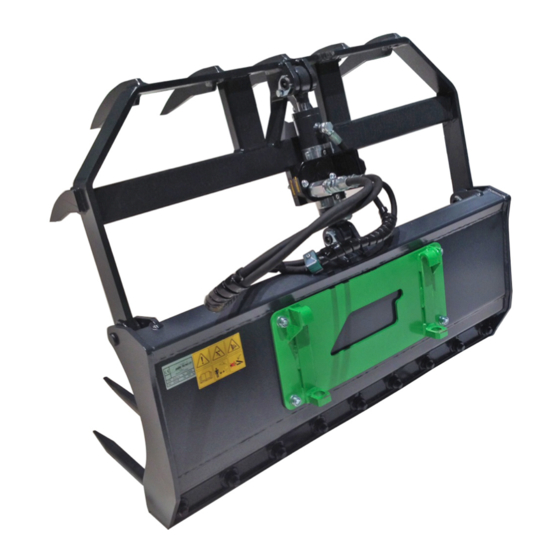
Page 22: Silage Dozer Blade (Optional Extra)
22 (28) 6.7 Silage dozer blade (optional extra) The silage fork is also possible to equip with a silage dozer blade. The blade is made of high-strength steel. In the bottom of the attachment, there is a durable nylon blade for equalizing the movement. The silage dozer blade A37111 is used for moving the uneaten silage back to the cattle on the feeding table. -
Page 23: Working On Uneven Ground
The adapter allows the attachment to be tilted sideways for efficient levelling or grading work. Read the instructions provided with the tilt adapter. More information about the tilt adapter is available from your AVANT dealer or from the AVANT web pages at www.avanttecno.com. -
Page 24: Maintenance And Service
Repair all leaks immediately after detecting them; a small leak can quickly grow into a big one. Operate the attachment only with type of hydraulic oil that is accepted for use in Avant loaders. Risk of high pressure fluid injection through skin - Release residual pressure before maintenance. -
Page 25: Inspection Of Metal Structures
Finding any fault means that the hydraulic hose or component must be replaced and the equipment must not be used until it is repaired. Spare parts are available from your nearest AVANT retailer or authorised service point. Leave the repair work to professional service technicians, if you don’t have adequate knowledge and experience about hydraulic assemblies and how to perform the repairing safely. -
Page 26: Warranty Terms
26 (28) 8. Warranty terms Avant Tecno Oy grants a warranty of one year (12 months) from the date of purchase for the attachment it manufactures. The warranty covers repair costs as follows: Work costs are covered, if the repair is not performed at the factory. - Page 27 SFS-EN ISO 12100, SFS-EN ISO 4413 Mallit / Modeller / Models: Avant Hydraulitoiminen rehupihti; Avant-kuormaajan työlaite A2868 Hydraulisk Foder-/ensilagegrep; arbetsredskap för Avant lastare A36299 Hydraulic Silage forks; attachment for Avant loaders A36313 A36319 28.5.2018 Ylöjärvi, Finland Risto Käkelä, Toimitusjohtaja / Verkställande direktör / Managing Director...
Need help?
Do you have a question about the A428628 and is the answer not in the manual?
Questions and answers