Banner L-GAGE LTF Instruction Manual
Time of flight laser distance
Hide thumbs
Also See for L-GAGE LTF:
- Quick start manual (7 pages) ,
- Quick start manual (8 pages) ,
- Instruction manual (38 pages)

Related Manuals for Banner L-GAGE LTF


Summary of Contents for Banner L-GAGE LTF
- Page 1 ® L-GAGE LTF Time of Flight Laser Distance Sensor Instruction Manual Original Instructions 194135 Rev. F 4 September 2018 © Banner Engineering Corp. All rights reserved 194135...
-
Page 2: Table Of Contents
6 Specifications ............................... 37 6.1 Repeatability Performance ............................... 38 6.2 Dimensions ..................................39 7 Troubleshooting ..............................40 8 Sensor Menu Full Map ............................41 9 Accessories ................................42 9.1 Cordsets ..................................42 9.2 Brackets ..................................42 10 Banner Engineering Corp. Limited Warranty ...................... 44... -
Page 3: Product Description
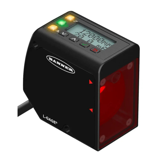
® L-GAGE LTF Time of Flight Laser Distance Sensor 1 Product Description Laser distance sensor with both analog and discrete (switched) outputs • High performance time of flight measurement • Extended ranges up to 24 m • Reliably detects challenging targets •... -
Page 4: Features And Indicators
® L-GAGE LTF Time of Flight Laser Distance Sensor 1.2.1 Features and Indicators Three LED indicators provide ongoing indication of the sensing status. Analog Output LED Indicator Analog Output LED Indicator Power Solid Amber = Displayed distance is within the taught Display LED Indicator analog output window... -
Page 5: Laser Description And Safety Information
® L-GAGE LTF Time of Flight Laser Distance Sensor Escape Button Press Escape to: • Leave the current menu and return to the parent menu • Return to Run mode from the Quick Menu Important: Pressing Escape discards any unsaved programming changes. In the Sensor Menu, a return arrow in the upper left corner of the display indicates that pressing Escape returns to the parent menu. -
Page 6: Sensor Installation
® L-GAGE LTF Time of Flight Laser Distance Sensor 2 Sensor Installation Note: Handle the sensor with care during installation and operation. Sensor windows soiled by fingerprints, dust, water, oil, etc. may create stray light that may degrade the peak performance of the sensor. -
Page 7: Sensor Programming
® L-GAGE LTF Time of Flight Laser Distance Sensor 3 Sensor Programming Program the sensor using the buttons on the sensor or the remote input (limited programming options). Quick Menu From Run mode, use the buttons to access the Quick Menu and the Sensor Menu. See on page 7 and Sensor Menu (MENU) on page 8 for more information on the options available from each menu. -
Page 8: Sensor Menu (Menu)
® L-GAGE LTF Time of Flight Laser Distance Sensor 3.2 Sensor Menu (MENU) Access the Sensor Menu by pressing Enter from Run mode. The Sensor Menu is also accessible from the Quick Menu: navigate to MENU and press Enter . The Sensor Menu includes several submenus that provide access to view and change sensor settings and to view sensor information. - Page 9 ® L-GAGE LTF Time of Flight Laser Distance Sensor NOTE: Follow procedure for the TEACH/SET method (highlighted in black box) chosen in the TEACH Selection menu. Pulse Timing (T) Mode Timeout is 60 seconds. 0.04 seconds < T < 0.8 seconds Timing between Pulse groups >...
-
Page 10: Locking And Unlocking The Sensor
® L-GAGE LTF Time of Flight Laser Distance Sensor Table 1: Remote TEACH Window Sizes Remote TEACH Window Size (mm) Remote TEACH Window Size (mm) Variable Variable LTF12 LTF24 LTF12 LTF24 2000 2000 11950 23950 3.4 Locking and Unlocking the Sensor Use the lock and unlock feature to prevent unauthorized or accidental programming changes. -
Page 11: Teach 4 Ma (0 V) And Teach 20 Ma (10 V)
® L-GAGE LTF Time of Flight Laser Distance Sensor MENU A_OUT A_OUT Tch2Pt Tch2Pt Tch4mA Tch4mA 50mm Tch2Pt Tch20mA Tch20mA 12000mm A_OUT TchMid TchMid WndSize WndSize +02000mm Tch12mA 6000mm TchMid Tch12mA Select Menu Item TchMid Offset Offset 0mm Press to Save Setting Adj4mA +00050mm A_OUT Adj4mA A_OUT Adj20mA... -
Page 12: Midpoint Teach
® L-GAGE LTF Time of Flight Laser Distance Sensor 2. Present the target. Action Result "RMT TCH" and the target's measurement Present the 4 mA (0 V) target. value display. 3. TEACH the sensor. Action Result "Tch4mA (Tch0V) Teaching" displays while the sensor is being taught. - Page 13 ® L-GAGE LTF Time of Flight Laser Distance Sensor The taught surface must be inside the defined sensing range, and at least one setpoint (with offset applied, if any) must be located within the sensing range. The Analog Output window size is a different setting than the Discrete Output window size when defined using the push buttons.
- Page 14 ® L-GAGE LTF Time of Flight Laser Distance Sensor Remote Input: Available Button Instructions 1. Present the target. Action Result The target's analog output measurement Present the target. and distance measurement values display. 2. Access the TEACH 12 mA (5 V) mode and TEACH the sensor. Action Result "Tch12mA (Tch5V) Teaching"...
-
Page 15: Adjust 4 Ma (0 V)
® L-GAGE LTF Time of Flight Laser Distance Sensor 3.5.3 Adjust 4 mA (0 V) The Adj4mA (Adj0V) option manually adjusts the distance at which the Analog Output is 4mA (0 V). The value is adjustable within the sensor's range. It is required to at least maintain the minimum window size. Navigate: MENU >... -
Page 16: Loss Of Signal
® L-GAGE LTF Time of Flight Laser Distance Sensor 2. Set the slope. Method Action Result a. The selection flashes rapidly on the a. Use Down and Up to change the slope between Positive display. and Negative. Push Button b. Press Enter to save the selection. -
Page 17: Two-Point Teach
® L-GAGE LTF Time of Flight Laser Distance Sensor • Mode • Timers • Polarity MENU D_OUT Tch2Pt TchSPt1 TchSPt1 50mm D_OUT Tch2Pt Tch2Pt TchSPt2 TchSPt2 12000mm D_OUT TchMid TchMid WndSize WndSize +00020mm TchMid TchMdPt TchMdPt 6000mm Select Menu Item Press to Save Setting TchMid Offset Offset 0mm... - Page 18 ® L-GAGE LTF Time of Flight Laser Distance Sensor Action Result The selected TEACH mode and "Teaching" display while the sensor is being taught. TEACH Accepted Navigate: MENU > D_OUT > Tch2Pt > TchSPt1 The new value is shown on the second line of the display and flashes before it is saved and the sensor returns to the parent menu.
-
Page 19: Midpoint Teach
® L-GAGE LTF Time of Flight Laser Distance Sensor Action Result "TchSPt2 Teaching" displays while the sensor is being taught. TEACH Accepted The new value displays on the second line Single-pulse the remote input. of the display, flashes, and the sensor returns to Run mode. - Page 20 ® L-GAGE LTF Time of Flight Laser Distance Sensor 2. Set the window size. Method Action Result a. "WndSize" and the new value a. Use Down and Up to set the desired window size—the display. value changes in increments of 2. Push Button b.
-
Page 21: Adjust Switch Point One
® L-GAGE LTF Time of Flight Laser Distance Sensor 2. Present the target. Action Result "RMT TCH" and the target's measurement Present the target. value display. 3. TEACH the sensor. Action Result "TchMdpt Teaching" displays while the sensor is being taught. TEACH Accepted The new value displays on the second line of the display, flashes, and the sensor... -
Page 22: Adjust Switch Point
® L-GAGE LTF Time of Flight Laser Distance Sensor 2. Access the switch point TEACH mode and TEACH the sensor. Action Result "TchSPt Teaching" displays while the sensor is being taught. TEACH Accepted The new value is shown on the second line Navigate: MENU >... - Page 23 ® L-GAGE LTF Time of Flight Laser Distance Sensor Mode Description Alarm Alarm Mode: The Discrete Output is Off while a target is detected by the sensor at any distance. When a loss of signal occurs, the Discrete Output is On. This mode has no associated thresholds.
-
Page 24: Switch Point Reference (Sptref)
® L-GAGE LTF Time of Flight Laser Distance Sensor Action Result Pulse the remote input 1 to 6 times to select the desired mode. Pulses Mode Alarm Health Swtch The selected mode flashes and the sensor returns to Run mode. Swtch 3.6.8 Switch Point Reference (SPtRef) The SPtRef menu only displays for a discrete output when it is set to switch mode. - Page 25 ® L-GAGE LTF Time of Flight Laser Distance Sensor Mode Swtch Swtch Output Output (On/Off) (On/Off) Object (Object) Hyst Hyst Hyst Hyst Background (Backgrnd) Near Near Figure 16. How hysteresis affects the sensor output based on the discrete output switchpoint mode and the setpoint reference mode Mode Output Output...
-
Page 26: Timer
® L-GAGE LTF Time of Flight Laser Distance Sensor 3.6.11 Timer The Timer option sets the delays and timers. On/Off Delays and On/Off One-Shot timers can Output be programmed between 1 to 9999 ms (a value Figure 19 of 0 disables the delay/timer). on page 26 defines how the delays/timers affect the output behavior. -
Page 27: Input Type
® L-GAGE LTF Time of Flight Laser Distance Sensor 3.7.1 Input Type The Type option sets the input type. Navigate: MENU > INPUT > Type Remote Input: Not available Default: Disabled Input Type Description Teach The remote input is used to TEACH and program the sensor. LasrEnbl The remote input is used to control when the laser emitter is On/Off. -
Page 28: Speed
® L-GAGE LTF Time of Flight Laser Distance Sensor 3.8.1 Speed The Speed option sets the speed at which the measurement is calculated. This process uses averaging in the digital processing of the signal to calculate the measurement. A slower speed increases the response time of the sensor but improves the repeatability. - Page 29 ® L-GAGE LTF Time of Flight Laser Distance Sensor Sample Input Signal Measuring Period Measuring Period Inactive REMOTE INPUT Active Hold Hold Measurement Measurement (Active Low shown) Figure 23. Sample Average Input Signal Measuring Period Measuring Period Inactive REMOTE INPUT Active Hold Hold...
-
Page 30: Display Menu (Display)
® L-GAGE LTF Time of Flight Laser Distance Sensor TrackMax Input Signal TrackMin Measuring Period Measuring Period Inactive REMOTE INPUT Active Hold Hold Measurement Measurement (Active Low shown) Figure 27. Track Maximum and Track Minimum 3.9 Display Menu (DISPLAY) Use this menu to view or change the: MENU DISPLAY Units mm... -
Page 31: View
® L-GAGE LTF Time of Flight Laser Distance Sensor This figure illustrates three examples of how changes to the zero and shift settings affect what distance readout is shown on the display when in 2-pt TEACH mode. Changes to the zero setting affect the direction in which the distance increases. Turning the shift setting on sets the taught location as the reference point for any distance measurement. -
Page 32: Sleep
® L-GAGE LTF Time of Flight Laser Distance Sensor Navigate: MENU > DISPLAY > View Remote Input: Not available Default: Normal Figure 30. Normal Display Orientation Figure 31. Inverted Display Orientation 3.9.4 Sleep The Sleep option sets when the display is put to sleep. Four timing options are available: 1, 5, 15, or 60 minutes. Sleep mode is disabled by default. -
Page 33: Reset Menu (Reset)
® L-GAGE LTF Time of Flight Laser Distance Sensor 3.11 Reset Menu (RESET) Use this menu to restore the sensor to the factory default settings. MENU RESET Navigate: MENU > RESET. Select Yes to apply the factory RESET No defaults; select No to return to the Reset option without RESET Yes changing any sensor settings. -
Page 34: Sync Master/Slave
® L-GAGE LTF Time of Flight Laser Distance Sensor 4 Sync Master/Slave Two LTF sensors may be used together in a single sensing application. To eliminate crosstalk between the two sensors, configure one sensor to be the master and one to be the slave. In this mode, the sensors alternate taking measurements and the response speed triples. -
Page 35: Additional Remote Teach Procedures
® L-GAGE LTF Time of Flight Laser Distance Sensor 5 Additional Remote TEACH Procedures 5.1 TEACH Analog Output and Discrete Output Switch Points Together Use the following procedure to teach identical Analog Output and Discrete Output switch points at the same time using the remote input. - Page 36 ® L-GAGE LTF Time of Flight Laser Distance Sensor 1. Access the TEACH mode. Action Result "RMT TCH" and the current measurement Single-pulse the remote input. value display. 2. Present the target. Action Result "RMT TCH"and the target's measurement Present the midpoint (switch point) target. value display.
-
Page 37: Specifications
® L-GAGE LTF Time of Flight Laser Distance Sensor 6 Specifications Supply Voltage Sensing Beam 12 to 30 V dc Visible red, 660 nm Power and Current Consumption (Exclusive of Load) Sensing Range -- LTF12 Normal Run Mode: < 2.1 W 90% White Target: 50 mm to 12000 mm Current consumption <... -
Page 38: Repeatability Performance
® L-GAGE LTF Time of Flight Laser Distance Sensor Storage Conditions Required Overcurrent Protection –30 °C to +65 °C (–22 °F to +149 °F) WARNING: Electrical connections must be Operating Conditions made by qualified personnel in accordance –20 °C to +55 °C (–4 °F to +131°F) with local and national electrical codes and 90% at +55 °C maximum relative humidity (non-condensing) regulations. -
Page 39: Dimensions
® L-GAGE LTF Time of Flight Laser Distance Sensor LTF24 Models 20 (0.79) 20 (0.79) 6% Black Card 6% Black Card 18 (0.71) 18 (0.71) 18% Gray Card 18% Gray Card 90% White Card 90% White Card 16 (0.63) 16 (0.63) 14 (0.55) 14 (0.55) 12 (0.47) -
Page 40: Troubleshooting
27. not active. All LEDs are flashing The laser shuts off, the Power LED flashes green, the Contact Banner Engineering to resolve. Output LEDs flash amber at 1 Hz, and the display is blank. The sensor has experienced a fault. -
Page 41: Sensor Menu Full Map
® L-GAGE LTF Time of Flight Laser Distance Sensor 8 Sensor Menu Full Map Top Menu Sub Menus Enter MENU A_OUT Tch2Pt Tch4mA Tch4mA 50mm A_OUT Tch2pt Mode Top Menu Tch2Pt Tch20mA Tch20mA 12000mm TchMid WndSize WndSize +02000mm A_OUT TchMid Tch12mA 6000mm TchMid Tch12mA TchMid Offset... -
Page 42: Accessories
® L-GAGE LTF Time of Flight Laser Distance Sensor 9 Accessories 9.1 Cordsets All measurements are listed in millimeters, unless noted otherwise. 5-Pin Threaded M12/Euro-Style Cordsets—with Shield Model Length Style Dimensions Pinout (Female) MQDEC2-506 1.83 m (6 ft) 44 Typ. MQDEC2-515 4.57 m (15 ft) Straight... - Page 43 ® L-GAGE LTF Time of Flight Laser Distance Sensor SMBAMSLTFIP • Includes the mounting plate and two protective windows • 90 plus degree rotation • Window frames are black anodized aluminum; mounting plate is stainless steel • The mounting plate, SMBAMSLTFP, can be ordered separately •...
-
Page 44: Banner Engineering Corp. Limited Warranty
10 Banner Engineering Corp. Limited Warranty Banner Engineering Corp. warrants its products to be free from defects in material and workmanship for one year following the date of shipment. Banner Engineering Corp. will repair or replace, free of charge, any product of its manufacture which, at the time it is returned to the factory, is found to have been defective during the warranty period. This warranty does not cover damage or liability for misuse, abuse, or the improper application or installation of the Banner product.
Need help?
Do you have a question about the L-GAGE LTF and is the answer not in the manual?
Questions and answers