Table of Contents
Advertisement
Quick Links
Advertisement
Table of Contents

Related Manuals for Fluke 7060


Summary of Contents for Fluke 7060
- Page 1 Hart Scientific 7060/7061 Calibration Bath Users Guide Rev. 740405...
- Page 2 Fluke Corporation, Hart Scientific Division • 799 E. Utah Valley Drive • American Fork, UT 84003-9775 • USA Phone: +1.801.763.1600 • Telefax: +1.801.763.1010 • E-mail: support@hartscientific.com www.hartscientific.com...
-
Page 3: Table Of Contents
Table of Contents 1 Before You Start ..... . 1 Symbols Used ......1 Safety Information . - Page 4 Lid ......26 8 General Operation ....27 Bath Fluid .
- Page 5 9.10.1 R0 ........46 9.10.2 ALPHA ....... . . 46 9.11 Operating Parameters .
- Page 6 13.2 Comments ......72 13.2.1 EMC Directive ......72 13.2.1.1 Emission Testing .
- Page 7 Figures Figure 1 Bath Assembly ....... 7 Figure 2 Semi-hermetic Compressor ......12 Figure 3 Front Panel .
- Page 8 Tables Table 1 International Electrical Symbols ..... . 1 Table 2 Cooling temperature chart ......23 Table 3 Table of Fluids .
-
Page 9: Before You Start
Before You Start Before You Start Symbols Used Table 1 lists the International Electrical Symbols. Some or all of these sym- bols may be used on the instrument or in this manual. Table 1 International Electrical Symbols Symbol Description AC (Alternating Current) AC-DC Battery CE Complies with European Union Directives... -
Page 10: Safety Information
7060/7061 User’s Guide Symbol Description Canadian Standards Association OVERVOLTAGE (Installation) CATEGORY II, Pollution Degree 2 per IEC1010-1 refers to the level of Impulse Withstand Voltage protection provided. Equipment of OVERVOLTAGE CATEGORY II is energy-con- suming equipment to be supplied from the fixed installation. Exam- ples include household, office, and laboratory appliances. - Page 11 Before You Start ergized for more than 10 days, the instrument needs to be energized for a "dry-out" period of 2 hours before it can be assumed to meet all of the safety requirements of the IEC 1010-1. If the product is wet or has been in a wet environment, take necessary measures to remove moisture prior to applying power such as storage in a low humidity temperature chamber operating at 50°C for 4 hours or more.
-
Page 12: Cautions
7060/7061 User’s Guide BATH FLUIDS • Fluids used in this bath may produce noxious or toxic fumes under cer- tain circumstances. Consult the fluid manufacturer’s MSDS (Material Safety Data Sheet). Proper ventilation and safety precautions must be observed. • The instrument is equipped with a soft cutout (user settable firmware) and a hard cutout (set at the factory). -
Page 13: Authorized Service Centers
Voltage Cut In: ±7.5% (213 - 247 VAC) Authorized Service Centers Please contact one of the following authorized Service Centers to coordinate service on your Hart product: Fluke Corporation, Hart Scientific Division 799 E. Utah Valley Drive American Fork, UT 84003-9775 Phone: +1.801.763.1600 Telefax: +1.801.763.1010... - Page 14 22 Jianguomenwai Dajie Chao Yang District Beijing 100004, PRC CHINA Phone: +86-10-6-512-3436 Telefax: +86-10-6-512-3437 E-mail: xingye.han@fluke.com.cn Fluke South East Asia Pte Ltd. Fluke ASEAN Regional Office Service Center 60 Alexandra Terrace #03-16 The Comtech (Lobby D) 118502 SINGAPORE Phone: +65 6799-5588 Telefax: +65 6799-5588 E-mail: antng@singa.fluke.com...
-
Page 15: Introduction
Digital remote communications is optionally available with a RS-232 or IEEE-488 interface. The tank for the 7060/7061 is stainless steel. The 7060 holds 25 liters and the 7061 holds 44 liters. There are two lids available: the standard lid with a rectangular access hole and an optional lid with a recirculation pump (see Figure 5). -
Page 16: Specifications And Environmental Conditions
Specifications and Environmental Conditions Specifications and Environmental Conditions Specifications 7060 7061 -60°C to 110°C Operating Range ±1.0°C Accuracy ±0.0025°C at -60°C (methanol) Stability ±0.002°C at 0°C (methanol) ±0.0015°C at 25°C (water) ±0.003°C at 100°C (oil 5012) ±0.005°C at -60°C (methanol) Uniformity ±0.005°C at 0°C (methanol) - Page 17 7060/7061 User’s Guide The instrument operates safely under the following conditions: • ambient temperature range: 5–50°C (41–122°F) • ambient relative humidity: maximum 80% for temperature <31°C, de- creasing linearly to 50% at 40°C • pressure: 75kPa–106kPa • mains voltage within ±10% of nominal •...
-
Page 18: Quick Start
This chapter gives a brief summary of the steps required to set up and oper- ate the 7060 or 7061 bath. This chapter should be used as a general over- view and reference and not as a substitute for the remainder of the manual. -
Page 19: Power
7060/7061 User’s Guide TOP VIEW OF COMPRESSOR Adjust HARDWARE ADJUSTED FOR SHIPPING Adjust BACK OF BATH HARDWARE ADJUSTED FOR OPERATION Figure 2 Semi-hermetic Compressor sult Section for detailed instructions for proper installation of the bath. Be sure to place the bath in a safe, clean and level location. -
Page 20: Setting The Temperature
Quick Start Setting the Temperature In the following discussion and throughout this manual a button around the word SET, U P, EXIT or DOWN indicates the panel button while the dotted box indicates the display reading. Explanation of the button or display read- ing are to the right of each button or display value. - Page 21 7060/7061 User’s Guide The bath will heat or cool until it reaches the new set-point temperature. Set the heater switch to position “HIGH” to allow the bath to more quickly reach a higher temperature. The “HIGH” setting may be necessary to reach and control at higher temperatures.
-
Page 22: Installation
IEC 1010-1. Bath Preparation and Filling The Model 7060/7061 Bath is not provided with a fluid. Various fluids are available from Hart Scientific and other sources. Depending on the desired temperature range, any of the following fluids, as well as others, may be used in the bath: •... -
Page 23: Probe
7060/7061 User’s Guide • Methanol • Halocarbon 0.8 • Mineral oil • Silicone oil Fluids are discussed in detail in Section 8.1. Remove any access hole cover from the bath and check the tank for foreign matter (dirt, remnant packing material, etc.). Use clean unpolluted fluid. - Page 24 Installation Use only wires and a circuit which are capable of supplying the maximum current (see Section 3.1). The wires must be fastened securely and insulated well. Plug the stirring motor power cord into the “STIRRER” socket at the back of the bath.
-
Page 25: Bath Use
Bath Use Bath Use READ BEFORE PLACING THE BATH IN SERVICE The information in this section is for general information only. It is not de- signed to be the basis for calibration laboratory procedures. Each laboratory will need to write their own specific procedures. General Be sure to select the correct fluid for the temperature range of the calibra- tion. -
Page 26: Calibration Of Multiple Probes
7060/7061 User’s Guide probes is not totally eliminated. Even though all baths have horizontal and vertical gradients, these gradients are minimized inside the bath work area. Nevertheless, probes should be inserted to the same depth in the bath liq- uid. Be sure that all probes are inserted deep enough to prevent stem effect. -
Page 27: Parts And Controls
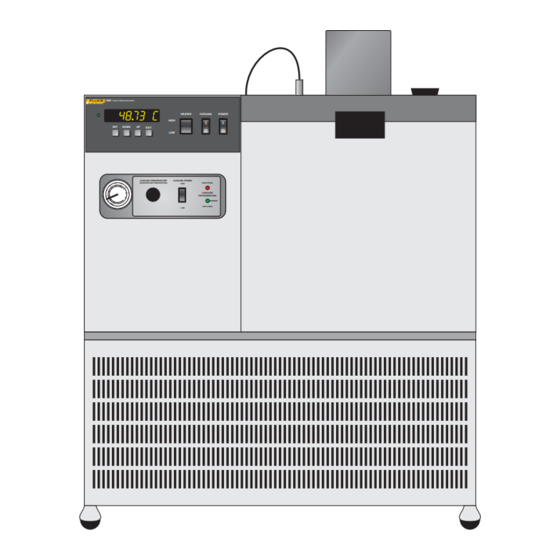
°C or °F. The control buttons (SET, DOWN, U P, and EXIT) are used to set the bath temperature set-point, access and set other operating parame- ters, and access and set bath calibration parameters. 7060 HIGH PRECISION BATH COOLING POWER... -
Page 28: Refrigeration Controls
7060/7061 User’s Guide A brief description of the functions of the buttons follows: SET – Used to display the next parameter in a menu and to set parameters to the displayed value. DOWN – Used to decrement the displayed value of settable parameters. -
Page 29: Back Panel
Parts and Controls ments that reduce the duty cycle percentage generally increase stability. Table 2 Cooling temperature chart R–23 Cooling Temperature Chart Set the Cooling Temp. Desired Bath Temperature Valve to This Pressure Degrees C Degrees F PSIG† –70 –94 –65 –85 –60... - Page 30 7060/7061 User’s Guide MAINS OUT OF RANGE PROBE STIRRER POWER IEEE-488 RS-232 Before opening disconnect mains. Vor Öffnen des Gehäuses Netzstecker ziehen. Avant d’ouvrir l’appereil retirez la fichemâle. SYSTEM FUSES INTERNAL DRAIN Figure 4 Back Panel The probe connector on the back panel connects the control probe to the temperature controller.
-
Page 31: Figure 5 Lid Options
Parts and Controls Optional Pump Lid Standard Lid Figure 5 Lid Options If the bath is supplied with a serial RS-232 interface, the interface cable is attached to the back of the bath at the connector labeled “SERIAL”. If the bath is supplied with a GPIB IEEE-488 interface, the interface cable is attached to the back of the bath at the connector labeled “IEEE”. -
Page 32: Lid
7060/7061 User’s Guide There are two different types of lids (see Figure 5). The standard lid has a stirring motor with rectangular access hole and the optional lid has a recirculation pump. Their features are described with reference to figure... -
Page 33: General Operation
General Operation General Operation Bath Fluid Many fluids will work with 7060/7061 bath. Choosing a fluid requires con- sideration of many important characteristics of the fluid. Among these are temperature range, viscosity, specific heat, thermal conductivity, thermal ex- pansion, electrical conductivity, fluid lifetime, safety, and cost. -
Page 34: Thermal Conductivity
7060/7061 User’s Guide proportional band to compensate for the change in the sensitivity of the bath temperature to heat input. 8.1.4 Thermal Conductivity Thermal conductivity measures how easily heat flows through the fluid. Thermal conductivity of the fluid affects the controller stability, temperature uniformity, and temperature settling time. -
Page 35: Cost
General Operation represents the contained vapors inside the tank and the open cup repre- sents the vapors escaping the tank. Oxygen and an ignition source will be less available inside the tank. Environmentally hazardous fluids require special disposal according to ap- plicable federal or local laws after use. -
Page 36: Halocarbon 0.8
7060/7061 User’s Guide perature capability can be well below –100°C but the viscosity can become excessive at such low temperatures. The viscosity is quite acceptable from –80°C up. A mixture of 50/50 methanol and water provides a non-flamma- ble solution capable of attaining –40°C. Because methanol has an infinite capability to absorb water, there is no ice formation below 0*°C. -
Page 37: Fluid Characteristics Charts
General Operation 8.1.11 Fluid Characteristics Charts Table 3 and Figure 6 on pages 33 and 32 have been created to provide help in selecting a heat exchange fluid media for your constant temperature bath. The charts provide both a visual and numerical representation of most of the physical qualities important in making a selection. -
Page 38: Figure 6 Chart Of Various Bath Fluids
7060/7061 User’s Guide –100°C 0°C 100°C 200°C 300°C 400°C 500°C 600°C Silicone Oil FL 302°C 10 CS 5017 Silicone Oil FL 280°C 10 CS 5014 Silicone Oil FL 232°C 10 CS 5013 Silicone Oil FL 211°C 5012 10 CS Silicone Oil FL 133°C... -
Page 39: Stirring
General Operation Table 3 Table of Fluids Fluid Lower Upper Thermal Thermal (# = Hart Part Temperature Temperature Flash Viscosity Specific Specific Heat Conductivity Expansion Resistivity No.) Limit* Limit* Point (centistokes) Gravity (cal/g/°C) (cal/s/cm/°C) (cm/cm/°C) -cm ) Halocarbon 0.8 –100°C (v)** 70°C (e) NONE 5.7 @ –50°C 1.71 @ 40°C... -
Page 40: Pump
7060/7061 User’s Guide Pump The bath may have the optional pump lid for recirculating bath fluid through equipment outside the bath. Be sure the hoses are fastened securely to the pump inlet and outlet tubes before operating the bath with the pump lid. -
Page 41: Cooling
Otherwise the temperature may oscillate. Cooling The Model 7060/7061 refrigeration system is a 2-stage cascade system. This means there are two individual refrigeration systems or stages. The first stage cools down or provides cooling for the second stage. The second stage cools the bath. -
Page 42: Fluid Drain
7060/7061 User’s Guide Fluid Drain The drain at the back of the bath (see Figure 4 on page 24) may be used to remove fluid from the bath. During operation of the bath the drain plug must be closed. Temperature Controller The bath temperature is controlled by Hart Scientific’s unique hybrid digi-... -
Page 43: Controller Operation
Controller Operation Controller Operation This chapter discusses in detail how to operate the bath temperature con- troller using the front control panel. Using the front panel key switches and LED display the user may monitor the bath temperature, set the temperature set-point in degrees C or F, monitor the heater output power, adjust the controller proportional band, set the cut-out set-point, and program the probe calibration parameters, operating parameters, serial and IEEE-488 in-... -
Page 44: Figure 7 Controller Operation Flowchart
7060/7061 User’s Guide Display Secondary Functions Temperature EXIT Display Power EXIT EXIT Reset Cutout Cutout Active Set Proportional Band EXIT Select Setpoint EXIT Set Cut-out Temp. EXIT Adjust Setpoint EXIT Adjust Vernier EXIT EXIT EXIT Set Scale °C/°F Configuration Menu... -
Page 45: Temperature Set-Point
Controller Operation Cut-out reset function rESEt ? Press “SET” once more to reset the cut-out. Reset cut-out This will also switch the display to the set temperature function. To return to displaying the temperature press the “EXIT” button. If the cut-out is still in the over-temperature fault condition the display will continue to flash “cut-out”. -
Page 46: Set-Point Value
7060/7061 User’s Guide Accept selected set-point memory 9.3.2 Set-point Value The set-point value may be adjusted after selecting the set-point memory and pressing “SET”. The set-point value is displayed with the units, C or F, at the left. Set-point 4 value in °C 40.00... -
Page 47: Temperature Scale Units
Controller Operation Access scale units Temperature Scale Units The temperature scale units of the controller may be set by the user to de- grees Celsius (°C) or Fahrenheit (°F). The units will be used in displaying the bath temperature, set-point, vernier, proportional band, and cut-out set-point. -
Page 48: Secondary Menu
7060/7061 User’s Guide Secondary Menu Functions which are used less often are accessed within the secondary menu. The secondary menu is accessed by pressing “SET” and “EXIT” simul- taneously and then releasing. The first function in the secondary menu is the heater power display. -
Page 49: Figure 8 Bath Temperature Fluctuation At Various Proportional Band Settings
Controller Operation perature and the controller cannot respond very well to changing conditions or noise in the system. If the proportional band is too narrow the bath tem- perature may swing back and forth because the controller overreacts to temperature variations. For best control stability the proportional band must be set for the optimum width. -
Page 50: Table 4 Proportional Band - Fluid Table
7060/7061 User’s Guide Table 4 Proportional Band — Fluid Table Proportional Fluid Temperature Heater Setting Band Stability ±0.001°C Methanol –80°C 0.04°C ±0.0008°C Methanol –40°C 0.04°C ±0.0008°C Water 0.0°C 0.04°C ±0.0004°C Water 30.0°C 0.04°C ±0.001°C Water 60.0°C 0.04°C ±0.0005°C Eth-Gly 50% 35.0°C... -
Page 51: Cut-Out
Controller Operation Cut-out As a protection against software or hardware fault, shorted heater triac, or user error, the bath is equipped with an adjustable heater cut-out device that will shut off power to the heater if the bath temperature exceeds a set value. -
Page 52: Controller Configuration
7060/7061 User’s Guide Accept cut-out set-point The next function is the configuration menu. Press “EXIT” to resume display- ing the bath temperature. Controller Configuration The controller has a number of configuration and operating options and cal- ibration parameters which are programmable via the front panel. These are accessed from the secondary menu after the cut-out set-point function by pressing “SET.”... -
Page 53: Cut-Out Reset Mode
Controller Operation Operating parameters menu Press “UP” to enter the menu. The operating parameters menu contains the cut-out reset mode parameter. 9.11.1 Cut-out Reset Mode The cut-out reset mode determines whether the cut-out resets automatically when the bath temperature drops to a safe value or must be manually reset by the operator. -
Page 54: Sample Period
7060/7061 User’s Guide 1200 b Current baud rate The baud rate of the bath serial communications may be programmed to 300,600,1200, or 2400 baud. Use “UP” or “DOWN” to change the baud rate value. 2400 b New baud rate Press “SET” to set the baud rate to the new value or “EXIT” to abort the op- eration and skip to the next parameter in the menu. -
Page 55: Linefeed
Controller Operation The mode may be changed using “UP” or “DOWN” and pressing “SET”. dUP=HALF New duplex mode setting 9.12.4 Linefeed The final parameter in the serial interface menu is the linefeed mode. This parameter enables (on) or disables (off) transmission of a linefeed character (LF, ASCII 10) after transmission of any carriage-return. -
Page 56: Calibration Parameters
9.14.1 Parameter CTO sets the calibration of the over-temperature cut-out. This is not adjustable by software but is adjusted with an internal potentiometer. For the 7060/7061 baths this parameter should read between 110 and 130. 9.14.2 BO and BG These parameters calibrate the accuracy of the bath set-point. These are programmed at the factory when the bath is calibrated. -
Page 57: Digital Communication Interface
Digital Communication Interface Digital Communication Interface If supplied with the option, the 7060/7061 bath is capable of communicat- ing with and being controlled by other equipment through the digital inter- face. Two types of digital interface are available — the RS-232 serial interface and the IEEE-488 GPIB interface. -
Page 58: Wiring
“baud”. Press “SET” to choose to set the baud rate. The current baud rate value will then be displayed. The baud rate of the 7060/7061 serial communications may be programmed to 300,600,1200, or 2400 baud. The baud rate is pre-programmed to 1200 baud. -
Page 59: Sample Period
Digital Communication Interface 10.1.2.2 Sample Period The sample period is the next parameter in the menu and prompted with “SAmPLE”. The sample period is the time period in seconds between tem- perature measurements transmitted from the serial interface. If the sample rate is set to 5, for instance, the bath will transmit the current measurement over the serial interface approximately every five seconds. -
Page 60: Ieee-488 Interface Address
7060/7061 User’s Guide To enter the IEEE-488 parameter programming menu first press “EXIT” while pressing “SET” and release to enter the secondary menu. Press “SET” repeatedly until the display reaches “PrObE”. This is the menu selection. Press “UP” repeatedly until the IEEE-488 interface menu is indicated with “IEEE”. -
Page 61: Table 5 Interface Command Summary
Digital Communication Interface Table 5 Interface Command Summary Command Command Returned Acceptable Command Description Format Example Returned Example Values Display Temperature Read current set-point s[etpoint] set: 9999.99 {C or set: 150.00 C Set current set-point to n s[etpoint]=n s=450 Instrument Range Read vernier v[ernier]... - Page 62 7060/7061 User’s Guide Interface Command Summary Cont. Command Command Returned Acceptable Command Description Format Example Returned Example Values Set cut-out mode: cm[ode]=r[eset]/a[ RESET or uto] AUTO Set cut-out to be reset cm[ode]=r[eset] cm=r manually- Set cut-out to be reset cm[ode]=a[uto]...
-
Page 63: Table 5 Interface Command Summary Cont
Digital Communication Interface Interface Command Summary Cont. Command Command Returned Acceptable Command Description Format Example Returned Example Values Read structure of all h[elp] list of commands commands Read Heater f1:9 f1:1 Set Heater f1=1/0 0 or 1 Set heater to low f1=n f1=0 Set heater to high... -
Page 64: Heater Control
“HIGH”, and adjusting the cooling temperature pressure to 5 psi. Otherwise, the interface would not be able to switch these functions off. The 7060/7061 bath has five control functions with the digital interface. These are 1) heater power high/low, 2) cooling on/off, 3) expansion valve 1 open/closed, 4) cooling power high/low, and 5) expansion valve 2 open/closed. -
Page 65: Table 6 Recommended Settings For General Operation
Digital Communication Interface Table 7 Serial Power Control Functions Function Command Heater high Refrigeration Exp. Valve 1 Cooling Power high Exp. Valve 2 Table 6 Recommended settings for general operation Bath Pressure Temperature Expansion Expansion Setting Range (°C) Heating Cooling Cooling Power Valve 1 Valve 2... -
Page 66: Calibration Procedure
Calibration Procedure Calibration Procedure In some instances the user may want to calibrate the bath to improve the temperature set-point accuracy. Calibration is done by adjusting the control- ler probe calibration constants R and ALPHA so that the temperature of the bath as measured with a standard thermometer agrees more closely with the bath set-point. -
Page 67: Computing R And Alpha
7060/7061 User’s Guide 11.3 Computing R and ALPHA Before computing the new values for R and ALPHA the current values must be known. The values may be found by either accessing the probe calibra- tion menu from the controller panel or by inquiring through the digital in- terface. -
Page 68: Figure 10 Sample Calibration Computations
Calibration Procedure = 100.000 ALPHA = 0.0038500 = 30.00°C measured t = 29.843°C = 80.00°C measured t = 79.914°C Compute errors, = 29.843 - 30.00°C = -0.157°C = 79.914 - 80.00°C = -0.086°C Compute R ⎡ ( ⎤ − × −... -
Page 69: Maintenance
Maintenance Maintenance The calibration instrument has been designed with the utmost care. Ease of operation and simplicity of maintenance have been a central theme in the product development. Therefore, with proper care the instrument should re- quire very little maintenance. Avoid operating the instrument in dirty or dusty environments. - Page 70 7060/7061 User’s Guide lar attention should be paid to the condensing coil fins. The fins should be vacuumed or brushed free of dust and dirt on a regular basis. Dust and dirt inhibit the operation of the condensing coil and thus compro- mise the performance and life-time of the cooling system.
-
Page 71: Draining The Bath
Maintenance able it should be changed. The instructions for removing the oil is as follows. 12.1 Draining the Bath WARNING: Extreme danger of BURNS and FIRE. Use safety equipment, use proper equipment and have fire safety equipment standing by. The drain is located on the back of the bath. See Figure 4 on page 24. Lo- cate the drain plug on the end of the drain tube. -
Page 72: Troubleshooting
Troubleshooting Troubleshooting In the event the bath appears to function abnormally this section may help to find and solve the problem. Several possible problem conditions are de- scribed along with likely causes and solutions. If a problem arises please read this section carefully and attempt to understand and solve the problem. If the bath seems faulty or the problem cannot otherwise be solved, then contact an Authorized Service Center for assistance. - Page 73 7060/7061 User’s Guide Problem Causes and Solutions The controller dis- If the display flashes “CUT-OUT” alternately with the correct pro- play flashes cess temperature, check the following: “CUT-OUT” and the heater does not Wrong cut-out setting. The cut-out disconnects power to the operate heaters when the bath temperature exceeds the cut-out set-point.
- Page 74 Troubleshooting Problem Causes and Solutions The controller con- If the controller appears to operate normally except that the trols or attempts to bath’s temperature does not agree with the temperature mea- control at an inaccu- sured by the user’s reference thermometer to within the specified rate temperature accuracy, consider the following: Erroneous parameters.
- Page 75 7060/7061 User’s Guide Problem Causes and Solutions The bath does not Too much heating. Check that the control indicator glows green achieve low showing that the controller is attempting to cool. The heaters may temperatures be disabled as a test by temporarily removing the heater fuses.
- Page 76 Troubleshooting As noted in the IEC 61326-1, the instrument can have varying configura- tions. The instrument was tested in a typical configuration with shielded RS-232 cables. 13.2.1.1 Emission Testing The instrument fulfills the limit requirements for Class A equipment but does not fulfill the limit requirements for Class B equipment.
Need help?
Do you have a question about the 7060 and is the answer not in the manual?
Questions and answers