Fluke 705 Manual
Loop calibrator
Hide thumbs
Also See for 705:
- Instruction sheet (17 pages) ,
- Specifications (1 page) ,
- Application note (8 pages)
Advertisement
To avoid electrical shock, remove test leads and any input signals from the
Model 705 Loop Calibrator before opening the case.
The Model 705 Loop Calibrator contains parts that can be damaged by static
discharge. Follow the standard practices for handling static sensitive
devices.
Introduction
The Calibration Information for the Model 705 Loop
Calibrator (hereafter referred to as the Loop
Calibrator) provides the information necessary to
calibrate and verify the performance of the Loop
Calibrator.
This document includes the following:
•
Contacting Fluke for service
•
•
Cleaning
•
•
Disassembly and reassembly
•
•
•
Calibration adjustments
•
User-replaceable parts
Complete operating instructions and the warranty
statement for the Model 705 Loop Calibrator are
provided in the Instruction Sheet that came with it.
PN 667345 December 1998, Rev.1, 12/99
©
1998, 1999 Fluke Corporation, All rights reserved. Printed in U.S.A.
All product names are trademarks of their respective companies.
Warning
Caution
Contacting Fluke for Service
This Fluke product will be free from defects in
material and workmanship for three years from the
date of purchase.
The complete warranty statement is in the Model 705
Loop Calibrator Instruction Sheet.
To locate an authorized service center, visit us on the
World Wide Web:
the phone numbers listed below:
•
1-888-99FLUKE (1-800-993-5853) in USA
•
1-800-36-FLUKE (1-800-363-5853) in Canada
•
+31 402-678-200 in Europe
•
+81-3-3434-0181 in Japan
•
+65-738-5655 in Singapore
•
+1-425-356-5500 from other countries
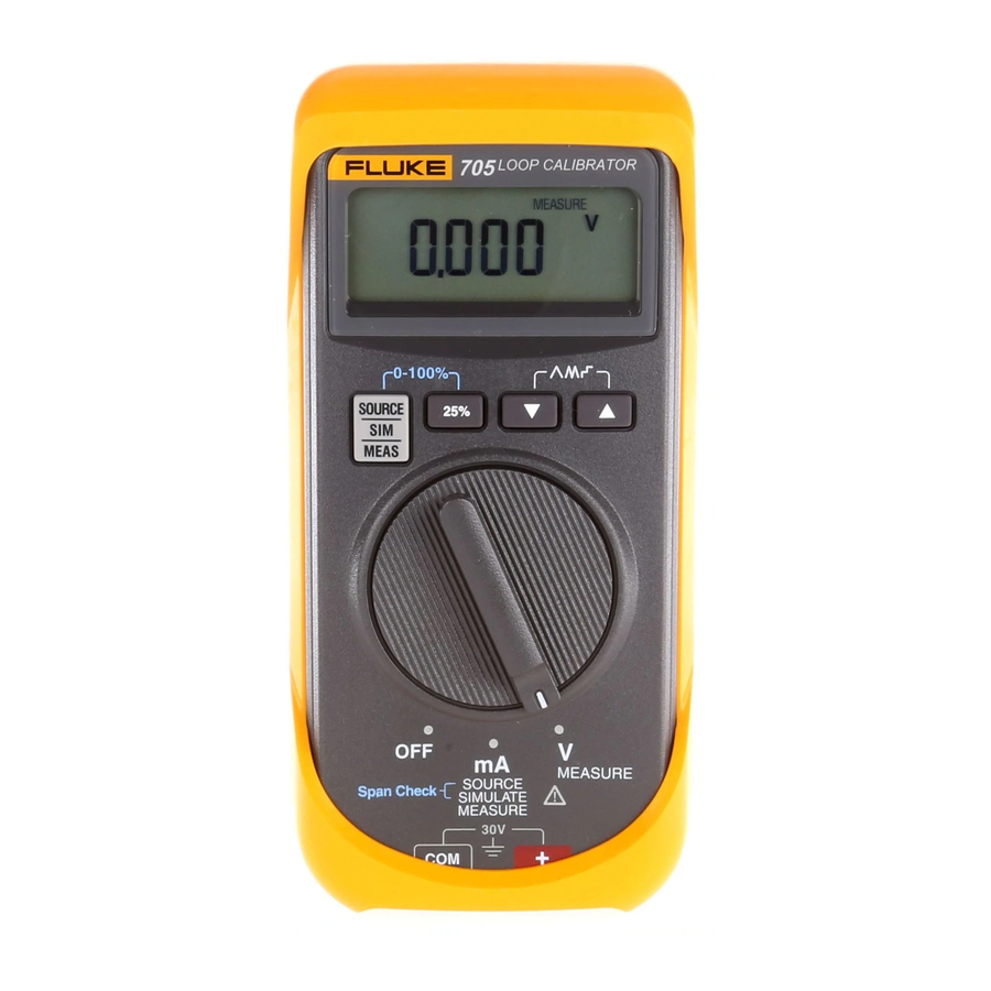
Model 705
Loop Calibrator
Calibration Information
or call Fluke using
www.fluke.com
®
1
Advertisement
Table of Contents

Related Manuals for Fluke 705


Summary of Contents for Fluke 705
- Page 1 To avoid electrical shock, remove test leads and any input signals from the Model 705 Loop Calibrator before opening the case. Caution The Model 705 Loop Calibrator contains parts that can be damaged by static discharge. Follow the standard practices for handling static sensitive devices.
-
Page 2: Specifications
Fluke 705 Calibration Information Specifications Product specifications are provided Tables 1 and 2. These specifications are based on a 1-year calibration cycle and apply from 18 ºC to 28 ºC (64 ºF to 82 ºF) unless stated otherwise. Accuracy specifications are given as follows: ±... -
Page 3: Replacing The Battery
Loop Calibrator Cleaning Disassembling and Reassembling the Cleaning Calibrator Warning Warning To avoid electrical shock, remove test To avoid electric shock or personal injury: leads and input signals before cleaning. • Do not allow water into the case. To clean the case, wipe it with a cloth lightly •... - Page 4 Fluke 705 Calibration Information Lens Case, Top Elastomeric Strip Elastomeric Strip (LCD to PCA) Keypad Assembly Actuator Switch Switch Support Assembly Case, Bottom Main PCA Screw, THD Form, PH.P.STL, 5-14 x .750 Battery Foot Battery Door AAK10F.EPS Figure 2. Disassembled Loop Calibrator...
- Page 5 Loop Calibrator Disassembling and Reassembling the Calibrator 10. To remove the switch support: Use a small, 11. To reinsert the pca: Place the pca over the four flat-blade screwdriver to gently unsnap the screw posts in the case top. sides and top of the switch support from the Gently press on the center of the pca while using snaps shown in Figure 2.
-
Page 6: Recommended Test Equipment
[ position. MEASURE 4. Set the Fluke 5500A to test 4 in Table 4 and The Loop Calibrator should display 4.000 mA. If verify the display readings on the Loop it is displaying 0.000 mA, turn the Loop Calibrator. - Page 7 Calibration will not function properly if low battery indicator is on. 3. Set the Fluke 5500A to test 7 in Table 4 and Because the Fluke 705 Loop Calibrator verify the display reading on the Loop Calibrator. incorporates several key hold start up Repeat for tests 8 and 9.
- Page 8 12. Connect the test leads from the terminals of 19. Remove all connections and place the rotary the Fluke 5500A to the terminals on the Loop switch of the Loop Calibrator to Calibrator (black to and red to [ The calibration procedure is now complete.
Need help?
Do you have a question about the 705 and is the answer not in the manual?
Questions and answers