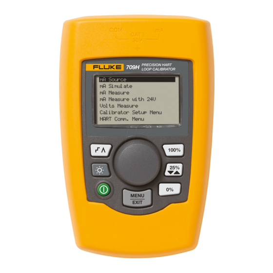
Fluke 709 Calibration Manual
Precision loop calibrator
Hide thumbs
Also See for 709:
- User manual (62 pages) ,
- Calibration manual (26 pages) ,
- Technical data (3 pages)
Table of Contents
Advertisement
Quick Links
Advertisement
Table of Contents

Related Manuals for Fluke 709


Summary of Contents for Fluke 709
- Page 1 709/709H/710 Precision Loop Calibrator Calibration Manual May 2013 Rev. 1, 12/18 © 2013-2018 Fluke Corporation. All rights reserved. Specifications are subject to change without notice. All product names are trademarks of their respective companies.
- Page 2 Fluke authorized resellers shall extend this warranty on new and unused products to end-user customers only but have no authority to extend a greater or different warranty on behalf of Fluke. Warranty support is available only if product is purchased through a Fluke authorized sales outlet or Buyer has paid the applicable international price.
-
Page 3: Table Of Contents
Table of Contents Title Page Introduction ......................1 Contact Fluke ..................... 1 Safety Information ....................2 Specifications ..................... 2 Maintenance ....................... 4 Clean the Product ..................4 Fuse ....................... 4 Battery Replacement ..................4 Required Test Equipment .................. 6 Performance Verification Tests ................6 DC Current Source Mode ................ - Page 4 709/709H/710 Calibration Manual...
-
Page 5: Introduction
To prevent possible electrical shock, fire, or personal injury, read all safety information before you use the Product. The Fluke 709, 709H, and 710 Precision Loop Calibrator (the Product or the Calibrator) can be used for installation, calibration, and troubleshooting of field transmitters, valves, and other control system components at process plants. -
Page 6: Safety Information
709/709H/710 Calibration Manual Safety Information For complete information about how to safely use this Product, read the 709/709H/710 Safety Information included with the Product or located on the Fluke website. Specifications Ranges mA ............0 mA to 24 mA Volts ............. 0 V dc to 30 V dc Resolution mA Ranges .......... - Page 7 Precision Loop Calibrator Specifications Safety ............IEC 61010-1: Pollution Degree 2 Electromagnetic Compatibility (EMC) International ......... IEC 61326-1: Portable Electromagnetic Environment IEC 61326-2-2 CISPR 11: Group 1, Class A Group 1: Equipment has intentionally generated and/or uses conductively-coupled radio frequency energy that is necessary for the internal function of the equipment itself.
-
Page 8: Maintenance
709/709H/710 Calibration Manual Maintenance XWWarning For safe operation and maintenance of the Product: • Repair the Product before use if the battery leaks. • Be sure that the battery polarity is correct to prevent battery leakage. • Remove the input signals before you clean the Product. - Page 9 Precision Loop Calibrator Maintenance gzx011.eps Figure 1. Battery Replacement...
-
Page 10: Required Test Equipment
Equipment Recommended Model Minimum Specification DC Voltage: 0 V to 30 V Accuracy: ±0.002 % +0.5 mV Fluke 5522A Multi-Product DC Calibrator Calibrator DC Current 0 mA to 24 mA Accuracy: ±0.002 % +0.5 μA DC Current: 0 mA to 26 mA... -
Page 11: Dc Current Source Mode
Precision Loop Calibrator Performance Verification Tests DC Current Source Mode To verify the performance of the dc current source function: 1. Turn on the Product. The Product shows 4.000 mA on the display. If the display does not show 4.000 mA: a. -
Page 12: Dc Current Measurement Mode
709/709H/710 Calibration Manual 3. Make sure that the Product shows SOURCE in the upper-left corner. 4. Set the DMM to measure dc current. 5. See Table 2 to verify the readings on the DMM for the subsequent tests. (No adjustment is necessary for Test 1.) - Page 13 Precision Loop Calibrator Performance Verification Tests 5522A 8508A hid014.eps Figure 3. DC Current Measurement Verification Connections 6. Adjust the Calibrator to output the value of test 4 in Table 2 as measured by the DMM, adjust the Calibrator if necessary to cause the DMM to show the necessary value. Then verify the display readings on the Product.
-
Page 14: Dc Voltage Measurement Mode
7. Turn the Product off and disconnect it from the Calibrator. If the Product failed any of these tests, calibration adjustment or repair is necessary. The performance verification tests for the 709 are now complete. For the 709H see the next section. -
Page 15: Hart Transmitter (709H/710 Only)
Precision Loop Calibrator Performance Verification Tests Hart Transmitter (709H/710 Only) 1. Push on the Product. 2. Turn the knob to select mA Measure with 24 V. 3. Connect the red jack to the + HART connection on a transmitter. Connect the black jack to the –... -
Page 16: Calibration Adjustment Procedure
709/709H/710 Calibration Manual Calibration Adjustment Procedure The Product features electronic calibration. There are no mechanical adjustments and calibration adjustment is done with its case closed. The calibration adjustment is done with the keypad. Use the display to guide you through the calibration process. -
Page 17: Ma Source
Precision Loop Calibrator Calibration Adjustment Procedure 4. Output 24 mA from the Calibrator. After the output is stable, push the knob to continue. As the Product takes readings, the screen shows ------- . When the readings are complete, the unit goes to the check mode. hid003.eps 5. -
Page 18: Voltage Measure
709/709H/710 Calibration Manual 5. Turn the knob on the Product to adjust the display until it shows the same as the DMM. After the output has become stable, push and hold the knob to continue. When the readings are complete, the Product will go to the check mode. -
Page 19: User-Replaceable Parts
Precision Loop Calibrator User-Replaceable Parts User-Replaceable Parts User-replaceable parts are listed in Table 3 and shown in Figure 6. For more information about these items and their prices, contact a Fluke representative. See the Contact Fluke section. Table 3. User-Replaceable Parts Item... - Page 20 709/709H/710 Calibration Manual hid009.eps Figure 6. User-Replaceable Parts...
Need help?
Do you have a question about the 709 and is the answer not in the manual?
Questions and answers