Table of Contents
Advertisement
Quick Links
• FAST SHIPPING AND
DELIVERY
• TENS OF THOUSANDS OF
IN-STOCK ITEMS
• EQUIPMENT DEMOS
• HUNDREDS OF
MANUFACTURERS
SUPPORTED
• LEASING/MONTHLY
RENTALS
• ITAR CERTIFIED
SECURE ASSET SOLUTIONS
Artisan Technology Group
new and certified-used/pre-owned equipment
SERVICE CENTER REPAIRS
Experienced engineers and technicians on staff
at our full-service, in-house repair center
View
Instra
REMOTE INSPECTION
SM
Remotely inspect equipment before purchasing with
www.instraview.com
our interactive website at
Contact us:
(888) 88-SOURCE | sales@artisantg.com | www.artisantg.com
is your source for quality
WE BUY USED EQUIPMENT
Sell your excess, underutilized, and idle used equipment
We also offer credit for buy-backs and trade-ins
www.artisantg.com/WeBuyEquipment
LOOKING FOR MORE INFORMATION?
Visit us on the web at
information on price quotations, drivers, technical
specifications, manuals, and documentation
www.artisantg.com
for more
Advertisement
Table of Contents

Related Manuals for Fluke 701


Summary of Contents for Fluke 701
- Page 1 Artisan Technology Group is your source for quality new and certified-used/pre-owned equipment SERVICE CENTER REPAIRS WE BUY USED EQUIPMENT • FAST SHIPPING AND DELIVERY Experienced engineers and technicians on staff Sell your excess, underutilized, and idle used equipment at our full-service, in-house repair center We also offer credit for buy-backs and trade-ins •...
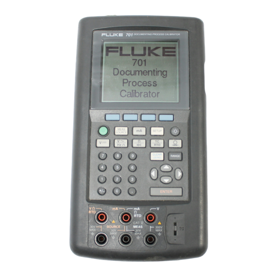
- Page 2 701/702 Documenting Process Calibrator Users Manual November 1994, Rev. 4, 3/98 © 1994, 1995, 1996, 1998 Fluke Corporation. All rights reserved. Printed in U.S.A. All product names are trademarks of their respective companies. Visit the Fluke website at: www.fluke.com ¨...
-
Page 4: Table Of Contents
Table of Contents Title Page Introduction......................1 Standard Equipment ..................4 Safety Information ..................... 10 Getting Acquainted with Your Calibrator ............12 Input and Output Jacks ................. 12 Keys ......................14 Display ......................17 Setting Up the Calibrator ................... 17 Using the Strap and Bail ................ - Page 5 701/702 Users Manual Selecting the Display Language ..............24 Adjusting the Display Contrast............... 24 Setting Up the Date and Time Display............24 Using the Backlight ..................25 Personalizing the Calibrator................26 Using Measure Mode ..................27 Measurement Ranges..................27 Measuring Electrical Parameters ..............28 Testing Continuity ..................
- Page 6 Contents (continued) Ramping the Output ..................55 Simultaneous Measure/Source ................. 59 Calibrating a Process Instrument ..............62 Generating “As Found” Test Data ..............62 Adjusting the Transmitter ................66 “As Left” Test Run ..................67 Memory Operations ................... 68 Saving Results ....................68 Reviewing Memory..................
- Page 7 701/702 Users Manual Resistance Measurement ................89 Continuity Testing ..................90 Frequency Measurement ................90 DC Voltage Output..................91 DC Current Output..................92 Resistance Sourcing ..................93 Frequency Sourcing..................94 Temperature, Thermocouples ............... 95 Temperature, Resistance Temperature Detectors ........98 Loop Power Supply..................
- Page 8 List of Tables Table Title Page Summary of Source and Measure Functions............3 Input/Output Jacks and Connectors............... 12 Key Functions ......................15 Battery Life......................22 Thermocouple Types Accepted ................34 RTD Types Accepted..................... 36 Simultaneous MEASURE/SOURCE Functions with Loop Power Disabled... 60 Simultaneous MEASURE/SOURCE Functions with Loop Power Enabled....
- Page 9 701/702 Users Manual...
- Page 10 List of Figures Figure Title Page Standard Equipment ....................5 Accessories......................8 Definition of Symbols ..................... 10 Input/Output Jacks and Connectors............... 13 Keys ........................14 Elements of a Typical Display................18 Installing the Strap and Using the Bail ..............19 Removing the Battery and Using the Charger ............
- Page 11 701/702 Users Manual Electrical Sourcing Connections ................42 Connections for Simulating a 4 to 20 mA Transmitter ..........44 Connections for Supplying Loop Power ..............46 Connections for Sourcing Pressure................ 49 Connections for Simulating a Thermocouple............51 Connections for Simulating an RTD ............... 53 Checking a Relay Output Trip Alarm ..............
-
Page 12: Introduction
See the back of this manual for PMLink software only.) complete specifications. PC interface for uploading/downloading In addition to the functions in Table 1, the 701 and procedures, lists, and results using PMLink 702 calibrators have the following features: software (Model 702 only). - Page 13 Users Manual Damping (smoothing of the last several Unless stated otherwise, everything in this readings). manual applies to both the Fluke 701 and 702 Documenting Process Calibrators. For Display of measurements in engineering units or maintenance, repair, performance testing, and percent of scale.
- Page 14 Documenting Process Calibrator Introduction Table 1. Summary of Source and Measure Functions FUNCTION MEASURE SOURCE 0 to ±300V v dc V 0 to 11V in V or mV units (10 mA max) h ac V 0 to 300V rms, 20 Hz to 5 kHz No sourcing h Frequency 1 Hz to 50 kHz, 110 mV to 300V rms...
-
Page 15: Standard Equipment
Jumper for three-wire RTD measurement end of this manual. connections (two included). • • TL24 industrial test leads (two sets). 701/702 Users Manual. • • AC20 test clips (two sets). 701/702 Quick Reference Guide. • • TP20 test probes (one set). Registration card. - Page 16 Documenting Process Calibrator Introduction ( ZERO) AC20 Test Clip TL24 Test Leads (2 Red and 2 Black) Jumper TP20 Test Probe Strap Figure 1. Standard Equipment...
- Page 17 701/702 Users Manual Users Mail-in Manual BP7217 Card Nickel-Cadmium Battery Pack BC7210 Battery Charger Quick Reference Guide Figure 1. Standard Equipment (cont)
- Page 18 The accessories listed below and shown in Figure 2 bench-top use. are available from Fluke: • PMLink software and cable for developing • Pressure Modules, Fluke model numbers listed procedures and transferring procedures and below. (Differential models also operate in gage data (for Model 702 only). mode.) •...
- Page 19 701/702 Users Manual Fluke-700P0X Differential Pressure Module BE9005 Battery Eliminator BP7217 Nickel-Cadmium Battery Pack Fluke-700P0X Gage Pressure Module Figure 2. Accessories...
- Page 20 Documenting Process Calibrator Introduction PMLink Manual PMLink Software RS-232 Cable 3.5-Inch Floppy Disk DB9 to DB25 (9-Pin to 25-Pin) Adapter PMLink Software Figure 2. Accessories (cont)
-
Page 21: Safety Information
701/702 Users Manual A WARNING identifies conditions and actions that Safety Information pose hazards to the user; a CAUTION identifies conditions and actions that may damage the wThis calibrator is designed and tested in calibrator or the equipment under test. - Page 22 Documenting Process Calibrator Safety Information • When using the probes, keep your fingers away To protect yourself, follow these safety guidelines: from the probe contacts. Keep your fingers • Do not use the calibrator if it is damaged. Before behind the finger guards on the probes. you use the calibrator, inspect the insulating •...
-
Page 23: Getting Acquainted With Your Calibrator
701/702 Users Manual Input and Output Jacks Getting Acquainted with Your Calibrator Figure 4 shows the calibrator input and output jacks. Table 2 explains their use. Table 2. Input/Output Jacks and Connectors ITEM FEATURE DESCRIPTION Battery Eliminator jack Jack for the Model BE9005 Battery Eliminator. Use the battery eliminator for bench- top applications where ac line power is available. - Page 24 Documenting Process Calibrator Getting Acquainted with Your Calibrator ( ZERO) 300V 30V MAX Figure 4. Input/Output Jacks and Connectors...
-
Page 25: Keys
701/702 Users Manual Keys Figure 5 shows the calibrator keys and Table 3 DOCUMENTING PROCESS CALIBRATOR explains their functions. The softkeys are the four unmarked blue keys just below the display. Softkey functions are defined by the labels that appear above the softkey during operation. - Page 26 Documenting Process Calibrator Getting Acquainted with Your Calibrator Table 3. Key Functions ITEM FEATURE DESCRIPTION M key Cycles the calibrator through MEASURE, SOURCE, and MEASURE/SOURCE modes. m key Selects mA (current) measure or source function. For loop power on/off, go to the s mode.
- Page 27 701/702 Users Manual Table 3. Key Functions (cont) ITEM FEATURE DESCRIPTION e key Terminates a numeric entry when setting a source value, or selects entries from lists. q key Toggles between resistance and continuity functions in MEASURE mode, or selects the resistance function in SOURCE mode.
-
Page 28: Display
Documenting Process Calibrator Setting Up the Calibrator Display Setting Up the Calibrator Figure 6 shows the features of a typical display. The This section consists of general information that display shown is MEASURE mode. Near the top of should be read before you use the calibrator. the display is “Source Off.”... - Page 29 701/702 Users Manual Loop Power Annunciator Battery Save Annunciator Status Bar Backlight Timeout Annunciator Mode Indicator Range Status Measured Value Softkey Labels Figure 6. Elements of a Typical Display...
- Page 30 Documenting Process Calibrator Setting Up the Calibrator Figure 7. Installing the Strap and Using the Bail...
-
Page 31: Charging The Battery
701/702 Users Manual NOTE Charging the Battery When you remove a charged battery from wBefore you use the calibrator for the first time, the charger, wait for the blinking indicator to charge its battery pack for 2 hours. Due to safety go off before you insert a discharged battery. -
Page 32: Battery Life
Documenting Process Calibrator Setting Up the Calibrator Battery Life Table 4 shows the operating time for a new, fully charged battery pack. Calibrator performance is guaranteed to meet specifications until the low battery annunciator blocated at the top right side of the display appears and the beeper beeps every 4 seconds. - Page 33 701/702 Users Manual Table 4. Battery Life OPERATING MODES BACKLIGHT OFF BACKLIGHT ON Measure, continuous 6.5 Hours 6 Hours Measure and source, with loop power on, continuous 3.5 Hours 3 Hours Typical intermittent operation >8 Hours >8 Hours...
-
Page 34: Automatically Saving Battery Life
6. operates the same as it does under battery power, however, the specifications for the 701/702 only 6. To change the timeout period, press d to apply under battery operation. The battery eliminator highlight the timeout period following Battery does not charge the battery. -
Page 35: Selecting The Display Language
701/702 Users Manual Selecting the Display Language Setting Up the Date and Time Display The calibrator displays information in five languages. The date and time are optionally displayed at the top of the display during normal operation. In s mode English language is the default. -
Page 36: Using The Backlight
Documenting Process Calibrator Setting Up the Calibrator 4. Press uor d to move the cursor to the desired 3. Use the u and dkeys to move the cursor to date format. the parameter you want to change, then press e or the Choices softkey to choose a 5. -
Page 37: Personalizing The Calibrator
701/702 Users Manual Auto Backlight Off is activated, the asymbol shows 10. Press the Done softkey or s to exit s at the top of the display. To automatically turn off the mode. backlight after a set time, proceed as follows: Personalizing the Calibrator 1. -
Page 38: Using Measure Mode
Documenting Process Calibrator Using Measure Mode Using Measure Mode NOTE To achieve best measurement noise and accuracy performance, do not use the battery eliminator, and tie all three common jacks together. The operating mode (i.e., MEASURE, SOURCE) is shown in a reverse-video bar on the display. If the calibrator is not in MEASURE mode, press M until 5. -
Page 39: Measuring Electrical Parameters
701/702 Users Manual If the range is locked, overrange inputs produce a NOTE display of - - - - - -. In Auto Range, out of range To measure frequency you are prompted to inputs produce a display of ! ! ! ! ! !. - Page 40 Documenting Process Calibrator Using Measure Mode 300V SOURCE MEAS 30V MAX – Black 300V SOURCE MEAS 30V MAX Black Figure 9. Electrical Measurement Connections...
-
Page 41: Testing Continuity
701/702 Users Manual measure the difference between the applied Testing Continuity pressure on the high fitting versus the low fitting. In the continuity function, the beeper sounds and the Figure 10 shows the two types. word Short appears on the display when the Proceed as follows to measure pressure: resistance between the Ω... - Page 42 Documenting Process Calibrator Using Measure Mode 3. Press p. The calibrator automatically senses CAUTION which pressure module is attached and sets its To avoid mechanically damaging the range accordingly. pressure module, never apply more than 10 ft.-lbs. of torque between the pressure 4.
- Page 43 701/702 Users Manual Isolation Valve Gage Module ( ZERO) 300V 30V MAX Differential Module Tank Figure 11. Connections for Measuring Pressure...
-
Page 44: Measuring Temperature
Documenting Process Calibrator Using Measure Mode 3. Press tso that the display prompting you to Measuring Temperature select the TC type shows. Using Thermocouples 4. Select the desired TC type using the u or d followed by e. The calibrator supports eleven standard thermocouples, each identified with an alpha 5. - Page 45 701/702 Users Manual Table 5. Thermocouple Types Accepted POSITIVE LEAD TYPE POSITIVE LEAD (H) COLOR NEGATIVE LEAD SPECIFIED RANGE MATERIAL MATERIAL (°C) ANSI* IEC** Chromel Purple Violet Constantan -250 to 1000 Ni-Cr-Si Orange Ni-Si-Mg -270 to 1300 Iron White Black...
- Page 46 Documenting Process Calibrator Using Measure Mode 300V Process Temperature SOURCE MEAS 30V MAX TC Minijack Figure 12. Measuring Temperature with a Thermocouple...
-
Page 47: Using Resistance-Temperature Detectors (Rtds)
701/702 Users Manual common R is 100Ω. Most RTDs come in a three- Using Resistance-Temperature Detectors terminal configuration. The calibrator accepts RTD (RTDs) measurement inputs in two-, three-, or four-wire connections. A four-wire configuration provides the The calibrator accepts RTD types shown in Table 6. - Page 48 Documenting Process Calibrator Using Measure Mode CAUTION To measure temperature using an RTD input, proceed as follows: Do not force a dual banana plug between any two jacks in the horizontal 1. If necessary, press M for MEASURE mode. orientation. (See the Figure.) Doing so 2.
- Page 49 701/702 Users Manual c. Use the u and d keys to move the cursor to the parameter you which to change, then press e or the Choices softkey to choose a setting for that parameter. WRONG d. Press u or d to move the cursor to the desired setting.
- Page 50 Documenting Process Calibrator Using Measure Mode 300V SOURCE MEAS 30V MAX 300V SOURCE MEAS 30V MAX 300V SOURCE MEAS 30V MAX Figure 13. Measuring Temperature with an RTD...
-
Page 51: Measurements In Percent Of Scale
The specifications assume that damping is turned on. The damping method is a running average of the last several measurements. Fluke 1. If necessary, press M for MEASURE mode. recommends that you leave damping on. Turning damping off may be useful when measurement 2. -
Page 52: Using Source Mode
Documenting Process Calibrator Using Source Mode NOTE 3. Enter the desired output value, then press e. For example, to source 5.0V dc, press If a measurement falls outside a random noise v 5 . 0 e. window, a new average is started. If damping is turned off, or until measurements are fully 4. - Page 53 701/702 Users Manual 300V SOURCE MEAS 30V MAX – Black Common 300V SOURCE MEAS 30V MAX – Black Common Figure 14. Electrical Sourcing Connections...
-
Page 54: Simulating A 4 To 20 Ma Transmitter
Documenting Process Calibrator Using Source Mode Simulating a 4 to 20 mA Transmitter You can configure the calibrator as a load on a current loop through the SOURCE mA function. When you press the M key in SOURCE mode, the display prompts you to select Source mA or Simulate Transmitter. - Page 55 701/702 Users Manual DOCUMENTING PROCESS CALIBRATOR MEAS SETUP SOURCE CLEAR RANGE ( ZERO) ENTER Loop Black Power 300V SOURCE MEAS 30V MAX Supply – Figure 15. Connections for Simulating a 4 to 20 mA Transmitter...
-
Page 56: Providing Loop Power
Documenting Process Calibrator Using Source Mode 2. Note that following Loop Power, Disabled is Providing Loop Power highlighted. Press e. The calibrator provides loop power at 28V or 24V dc. 3. Use the u or d arrow keys to select Enabled The 28V setting provides enough current for two or 24V or Enabled 28V. - Page 57 701/702 Users Manual DOCUMENTING PROCESS CALIBRATOR MEAS SETUP SOURCE TEST DC PWR CLEAR RANGE – + – ( ZERO) ENTER – 300V SOURCE MEAS 30V MAX Black Figure 16. Connections for Supplying Loop Power...
-
Page 58: Sourcing Pressure
Documenting Process Calibrator Using Source Mode WARNING Sourcing Pressure TO AVOID A VIOLENT RELEASE OF The calibrator provides a source pressure display PRESSURE IN A PRESSURIZED SYSTEM, function that requires the use of an external pressure SHUT OFF THE VALVE AND SLOWLY hand pump. - Page 59 701/702 Users Manual To avoid damaging the pressure module 5. Pressurize the pressure line with the pressure from corrosion, use them only with source to the desired level as shown on the specified materials. Refer to the pressure display. module instruction sheet for the 6.
- Page 60 Documenting Process Calibrator Using Source Mode Pressure Module DOCUMENTING PROCESS CALIBRATOR Hand Pump MEAS SETUP SOURCE CLEAR RANGE ( ZERO) ENTER 300V SOURCE MEAS 30V MAX Figure 17. Connections for Sourcing Pressure...
-
Page 61: Simulating Thermocouples
701/702 Users Manual 3. Press tfor the display that prompts you to Simulating Thermocouples enter thermocouple type. NOTE 4. Press the u or d key followed by e to Refer to “Measuring Temperature” earlier in the select the desired thermocouple type. - Page 62 Documenting Process Calibrator Using Source Mode DOCUMENTING PROCESS CALIBRATOR TEST DC PWR Color depends – on type of TC – MEAS SETUP SOURCE CLEAR RANGE ( ZERO) ENTER 300V SOURCE MEAS 30V MAX TC Minijack Figure 18. Connections for Simulating a Thermocouple...
-
Page 63: Simulating Rtds
701/702 Users Manual 1. If necessary, press M for SOURCE mode. Simulating RTDs 2. Press tuntil the select RTD type display is NOTE showing. Refer to Table 6 for information about RTD 3. Press the u or d keys followed by e to (Resistance Temperature Detector) types select the desired RTD type. - Page 64 Documenting Process Calibrator Using Source Mode Transmitter Black 300V SOURCE MEAS 30V MAX Figure 19. Connections for Simulating an RTD...
-
Page 65: Sourcing In Percent Of Scale
701/702 Users Manual 6. Use the numeric keypad to enter the 100% of Sourcing in Percent of Scale scale value. To adjust the source value as a percent of scale as 7. Press e. shown below, proceed as follows: 8. Press the Done softkey. -
Page 66: Ramping The Output
Documenting Process Calibrator Using Source Mode works in SOURCE and in MEASURE/SOURCE Ramping the Output modes. Proceed as follows to select a step size: Ramping is sweeping the source up or down in 1. Refer to the appropriate heading earlier in this value. - Page 67 701/702 Users Manual and connect the calibrator to the circuit to be 7. Press the Ramp softkey. The display changes to tested. Figure 20 shows an example. the following: 2. If you want to automatically stop ramping if a trip...
- Page 68 Documenting Process Calibrator Using Source Mode 8. Fill in the parameters as prompted. Enter the 11. Select a low-to-high ramp or a high-to-low ramp Start Value, End Value, and Ramp Time. with the Ramp Up/Down softkey. 9. If you want to automatically stop ramping if a trip 12.
- Page 69 701/702 Users Manual DOCUMENTING PROCESS CALIBRATOR Trip Relay Voltage Trip Detect Output – MEAS SETUP SOURCE CLEAR RANGE ( ZERO) Input 4 – 20 mA ENTER – Black 300V SOURCE MEAS 30V MAX Black Source mA Figure 20. Checking a Relay Output Trip Alarm...
-
Page 70: Simultaneous Measure/Source
Documenting Process Calibrator Simultaneous Measure/Source Table 7 shows the functions you can use Simultaneous Measure/Source simultaneously when Loop Power is disabled. Table 8 shows the functions you can use simultaneously Use MEASURE/SOURCE mode to calibrate process when Loop Power is enabled. instruments. - Page 71 701/702 Users Manual Table 7. Simultaneous MEASURE/SOURCE Functions with Loop Power Disabled SOURCE FUNCTION MEASURE FUNCTION Ω dc V Freq 2W RTD Pressure • • • • • • • dc V • • • • • • • •...
- Page 72 Documenting Process Calibrator Simultaneous Measure/Source Table 8. Simultaneous MEASURE/SOURCE Functions with Loop Power Enabled SOURCE FUNCTION MEASURE FUNCTION Ω dc V Freq 2W RTD Pressure • • • • • • dc V • • • • • • • •...
-
Page 73: Calibrating A Process Instrument
701/702 Users Manual 2. If necessary, press M for MEASURE mode. Calibrating a Process Instrument 3. Press M. When the calibrator is in simultaneous MEASURE/SOURCE mode, a built-in calibration 4. Press M for SOURCE mode. routine is activated when you press the As Found 5. - Page 74 Documenting Process Calibrator Calibrating a Process Instrument DOCUMENTING PROCESS CALIBRATOR Color depends TEST DC PWR on type of TC – – MEAS SETUP SOURCE CLEAR RANGE ( ZERO) Original ENTER Circuit Wiring 300V SOURCE MEAS 30V MAX Power – Minijack Supply Black Figure 21.
- Page 75 701/702 Users Manual NOTE 9. Press the As Found softkey. The display changes as follows: If you set User-Entered Value to Enabled, you will be prompted to enter a value at each test point in the measured units. Errors will be calculated and displayed based on the user-entered value, not the measured value.
- Page 76 Documenting Process Calibrator Calibrating a Process Instrument 13. Press the Done softkey to accept the calibration 14. You now have the choice of starting an parameters. The display changes as follows: automatic test or stepping through the test points manually. Press the Auto Test softkey to have the calibrator run through the tests automatically.
-
Page 77: Adjusting The Transmitter
701/702 Users Manual value is shown in the top left of the measure failures were outside the ±0.5% tolerance that window. we selected. 15. The calibrator moves on to the remaining set of 17. Either press the Done softkey to save the data, points. -
Page 78: As Left" Test Run
Documenting Process Calibrator Calibrating a Process Instrument • Go to 100%/Go to 0% 2. Press the Auto Test softkey to begin an • Go to 50% automatic sequence through all the test points, • As Left or you can step through the tests manually. •... -
Page 79: Memory Operations
701/702 Users Manual Memory Operations Saving Results As Found/As Left test results are automatically saved at the end of each test routine. Any other time during MEASURE, SOURCE, or MEASURE/SOURCE you can press the Save softkey to save the data on the display for later review. -
Page 80: Reviewing Memory
Documenting Process Calibrator Memory Operations Enter alphanumeric data by pressing e with 1. Enter numbers with the numeric keypad. the cursor on the field you would like to change (for 2. Enter letters or a space character by highlighting example, Tag, above). The display presents you with the desired character with the u, d, L, and R an alphanumeric entry window as follows: keys and pressing e. -
Page 81: Data Logging (Model 702 Only)
701/702 Users Manual When you press the Review Memory softkey, the display changes to the following: Proceed as follows to log data: 1. If necessary, press M for MEASURE mode. Press e to view a saved result.w 2. Press the More Choices softkey. - Page 82 Documenting Process Calibrator Memory Operations 7. Use the numeric keypad to enter the duration in CAUTION minutes, followed by e. The maximum A long logging duration can exceed the duration will depend on the reading rate and how life of a battery charge. Use a fresh much memory is available to log data.
-
Page 83: Observing Min And Max Measurements
701/702 Users Manual 9. Press the Done softkey. The display changes to Observing Min and Max Measurements the following: You can set the display to record and show the maximum and minimum readings. Min and Max readings are always undamped, even if Dampen is On. -
Page 84: Clearing Memory
Documenting Process Calibrator Quick Guide to Applications the list of tasks (procedures) downloaded from Quick Guide to Applications PMLink. Tasks are 702 calibrator configurations, saved with a procedure name, for example the type The following figures show test lead connections and and manufacturer of a specific transmitter. - Page 85 701/702 Users Manual Measure V DOCUMENTING PROCESS CALIBRATOR DOCUMENTING PROCESS CALIBRATOR MEAS SETUP SOURCE MEAS SETUP SOURCE CLEAR RANGE (ZERO) CLEAR RANGE (ZERO) Circuit 0 to 1V dc ENTER Ω Input ENTER 300V SOURCE MEAS 30V MAX Black 300V SOURCE...
- Page 86 Documenting Process Calibrator Quick Guide to Applications Measure DOCUMENTING PROCESS CALIBRATOR MEAS SETUP SOURCE CLEAR RANGE (ZERO) ENTER 300V SOURCE MEAS 30V MAX BLACK Figure 24. Monitoring AC Line Voltage and Frequency...
- Page 87 701/702 Users Manual Measure Pressure DOCUMENTING PROCESS CALIBRATOR Source mA Loop Power Disabled S I G N A L – T E S T MEAS Pressure SETUP SOURCE Module CLEAR RANGE ( ZERO) ENTER 300V SOURCE MEAS 30V MAX Black...
- Page 88 Documenting Process Calibrator Quick Guide to Applications Measure mA Loop Power Disabled DOCUMENTING PROCESS CALIBRATOR TEST DC PWR – – MEAS SETUP SOURCE CLEAR RANGE ( ZERO) Original ENTER Circuit Wiring 300V SOURCE MEAS 30V MAX Power – Supply Black Figure 26.
- Page 89 701/702 Users Manual Source Resistance Measure Resistance DOCUMENTING PROCESS CALIBRATOR DOCUMENTING PROCESS CALIBRATOR MEAS SETUP SOURCE MEAS SETUP SOURCE CLEAR RANGE (ZERO) CLEAR RANGE ( ZERO) ENTER ENTER 300V SOURCE MEAS 30V MAX Circuit 300V SOURCE MEAS 30V MAX Black Black Figure 28.
- Page 90 Documenting Process Calibrator Quick Guide to Applications Measure Measure Continuity Frequency DOCUMENTING PROCESS CALIBRATOR DOCUMENTING PROCESS CALIBRATOR MEAS MEAS SETUP SETUP SOURCE SOURCE CLEAR CLEAR RANGE RANGE (ZERO) (ZERO) ENTER ENTER 300V 300V SOURCE MEAS SOURCE MEAS 30V MAX 30V MAX Black Black Figure 29.
- Page 91 701/702 Users Manual Measure mA Hand Pump Source Pressure DOCUMENTING PROCESS CALIBRATOR Loop Power Enabled 24V S I G N A L – T E S T MEAS SETUP SOURCE Pressure Module CLEAR RANGE ( ZERO) ENTER 300V SOURCE MEAS...
- Page 92 Documenting Process Calibrator Quick Guide to Applications DOCUMENTING PROCESS CALIBRATOR Measure mA Output – Input 0 – 1mV, 0 – 10mV, 0– 100mV, 1 – 5V, MEAS 0 – 1V, 0 – 10V SETUP SOURCE Output CLEAR RANGE ( ZERO) 4–20 mA Input ENTER...
- Page 93 701/702 Users Manual Measure DOCUMENTING PROCESS CALIBRATOR Frequency Black MEAS SETUP SOURCE CLEAR RANGE (ZERO) ENTER 300V SOURCE MEAS 30V MAX Figure 33. Checking a Vortex Shedding Flowmeter...
-
Page 94: Communicating With A Pc (Model 702 Only)
Documenting Process Calibrator Communicating with a PC (Model 702 Only) Canada call Fluke Service Parts at (800) 526-4731. Communicating with a PC (Model Outside the USA and Canada call +1 206-356-5500 to receive instructions. 702 Only) Do not mix spent Nickel-Cadmium batteries with You can upload and download procedures and the solid waste stream. -
Page 95: Calibration Data
Table 9 lists the user-replaceable parts for the Model needed. 701 and 702. If the item has a Fluke Model Number, Verify that the calibrator is being operated in order it by that number. Otherwise, use the Fluke accordance with the instructions in this manual. - Page 96 Battery Door 938357 Bail 938340 Bail Screw 943431 Case Screw 942797 Lens for Model 701 938217 Lens for Model 702 938212 Input/Output Jack Decal 946756 701/702 Users Manual 943993 701/702 Quick Reference Guide (Set) 942784 Battery Eliminator BE9005 Service Kit 926113...
-
Page 97: Specifications
"% of full scale." The measure pressure, temperature, and frequency functions are specified only with damping on. The standard specification intervals for the 701 and 702 are 1 and 2 years. Ttpical 90-day source and measurement accuracy can be estimated by dividing the 1 year "% of Reading"... -
Page 98: Dc Voltage Measurement
Documenting Process Calibrator Specifications DC Voltage Measurement MODEL 702 MODEL 701 RANGE RESOLUTION % OF READING +% OF FULL SCALE % OF READING +% OF FULL SCALE 1 YEAR 2 YEAR 1 YEAR 2 YEAR 1 µV 110 mV 0.025% + 0.015% 0.05% + 0.015%... -
Page 99: Ac Voltage Measurement
701/702 Users Manual AC Voltage Measurement MODEL 701 AND 702 FREQUENCY RANGE (% OF READING + NUMBER OF COUNTS) 1 YEAR 2 YEAR 20 to 40 Hz 2% + 10 2% + 10 40 to 500 Hz 0.5% + 5 0.5% + 5... -
Page 100: Dc Current Measurement
Documenting Process Calibrator Specifications DC Current Measurement MODEL 702 MODEL 701 RANGE RESOLUTION % OF READING +% OF FULL SCALE % OF READING +% OF FULL SCALE 1 YEAR 2 YEAR 1 YEAR 2 YEAR 1 µA 30 mA 0.025% + 0.025% 0.025% + 0.03%... -
Page 101: Continuity Testing
<25 Ω Continuous Tone 25 to 400 Ω May or may not get tone >400 Ω No tone Frequency Measurement MODEL 701 AND 702 RANGES COUNTS 1 YEAR 2 YEAR 1 Hz to 109.99 Hz 110 Hz to 1099.9 Hz 1.100 kHz to 10.999 kHz... -
Page 102: Dc Voltage Output
Documenting Process Calibrator Specifications DC Voltage Output MODEL 702 MODEL 701 RANGE RESOLUTIONS % OUTPUT +% OF FULL SCALE % OUTPUT + % OF FULL SCALE 1 YEAR 2 YEAR 1 YEAR 2 YEAR 1 µV 110 mV 0.01% + 0.005% 0.015% + 0.005%... -
Page 103: Dc Current Output
701/702 Users Manual DC Current Output MODELS 701 AND 702 RANGE RESOLUTION % OUTPUT +% OF FULL SCALE 1 YEAR 2 YEAR 1 µA 22 mA 0.01% + 0.04% 0.02% + 0.06% Maximum Burden Voltage: 24V Temperature Coefficient: (0.003% of output + 0.003% of f.s.)/°C in the ranges -10 to 18°C and 28 to 50°C Common Mode Error: 0.008% f.s/(Common Mode Volt) -
Page 104: Resistance Sourcing
Documenting Process Calibrator Specifications Resistance Sourcing MODEL 702 MODEL 701 RANGES RESOLUTION % OUTPUT + OHMS % OUTPUT + OHMS 1 YEAR 2 YEAR 1 YEAR 2 YEAR 0.03% + 0.02 11.000Ω 1 mΩ 0.01% + 0.02 0.02% + 0.02 0.02% + 0.02... -
Page 105: Frequency Sourcing
701/702 Users Manual Frequency Sourcing MODELS 702 AND 701 FREQUENCY RANGES COUNTS 1 YEAR 2 YEAR 2 Hz to 109.99 Hz 110 Hz to 1099 Hz 1.1 kHz to 10.9 kHz 11 kHz to 50 kHz Waveform: Squarewave, 50% duty cycle... -
Page 106: Temperature, Thermocouples
Documenting Process Calibrator Specifications Temperature, Thermocouples MEASURE DEGREES C SOURCE DEGREES C TYPES (°C) 1 YEAR 2 YEAR 1 YEAR 2 YEAR -250 to -200 -200 to -100 -100 to 600 600 to 1000 -200 to -100 -100 to 900 900 to 1300 -210 to -100 -100 to 800... - Page 107 701/702 Users Manual Temperture, Thermocouples (cont) MEASURE DEGREES C SOURCE DEGREES C TYPES (°C) 1 YEAR 2 YEAR 1 YEAR 2 YEAR -200 to -100 -100 to 400 400 to 1200 1200 to 1372 -250 to -200 -200 to 0...
- Page 108 Documenting Process Calibrator Specifications Temperature, Thermocouples (cont) MEASURE DEGREES C SOURCE DEGREES C TYPES (°C) 1 YEAR 2 YEAR 1 YEAR 2 YEAR -20 to 0 0 to 100 100 to 1767 -20 to 0 0 to 200 200 to 1400 1400 to 1767 0 to 800 800 to 1200...
-
Page 109: Temperature, Resistance Temperature Detectors
701/702 Users Manual Temperature, Resistance Temperature Detectors Temperature, RTDs, Model 702 and 701 TYPES (°C) MEASURE DEGREES C SOURCE DEGREES C 1 YEAR 2 YEAR 1 YEAR 2 YEAR 100 Ω Pt(385) -200 to 0 0 to 400 400 to 800 100 Ω... -
Page 110: Loop Power Supply
Temperature Coefficient: 0.02°C/°C in the ranges -10 to 18°C and 28 to 50°C Maximum Input Voltage: 30V For two and three-wire RTD measurements, add 0.4°C to the specifications. Loop Power Supply MODELS 702 AND 701 SETTING 1 YEAR 2 YEAR... -
Page 111: Top And Bottom Limits Of Ranges With Auto Range On
701/702 Users Manual Top and Bottom Limits of Ranges with Auto Range On RANGE, DC V MEASURE TOP OF RANGE BOTTOM OF RANGE 110 mV ±110.000 mV 0.000 mV 1.1 V ±1.10000 V ±0.10000 V 11 V ±11.0000 V ±1.0000 V 110 V ±110.000 V... - Page 112 Documenting Process Calibrator Specifications Top and Bottom Limits of Ranges with Auto Range On (cont) RANGE, MEASURE V CC 110 mA +110.00 mA +30.00 mA RANGE, CURRENT SOURCE 22 mA +30.000 mA 0.000 mA RANGE, FREQUENCY MEASURE 100 Hz 109.99 Hz 1.00 Hz 1 kHz 1099.9 Hz...
-
Page 113: General Specifications
701/702 Users Manual General Specifications Display: 240 by 200 pixel graphic LCD, 70 x 58 mm. Power: Internal Battery Pack: NiCd, 7.2V, 1700 mAhr. Memory Backup: Lithium battery, 5 years typical lifetime. Dimensions: 130 x 236 x 61 mm (5.1 x 9.3 x 2.4 in.). - Page 114 Documenting Process Calibrator Specifications 100 120 Temperature (deg F) Temperature (deg C) ˚ ˚ = Storage (-20 C — 60 ˚ ˚ = Normal Operation (-10 C — 50 Figure 34. Operating Environment Specification...
- Page 115 701/702 Users Manual...
-
Page 116: Index
Index —4— —B— —C— 4 to 20 ma transmitter Backlight, 25 Calibrating a process instru- simulating, 43 auto timeout, 26 ment, 62 Bail, 17 Calibration, 84 Battery data, 84 —A— auto save timeout, 23 Cleaning As found test data, 62 charge life, 21 the calibrator, 83 As left test data, 67... - Page 117 701/702 Users Manual for measuring pressure, 32 Measuring —J— Continuity continuity, 30 Jacks, 12 testing, 30 current, 28 trip detect during ramping, 55 electrical parameters, 28 —K— Contrast frequency, 28 adjusting display, 24 pressure, 30 Key functions, 14 Current resistance, 28...
- Page 118 Index (continued) connections for measuring, pressure, 47 —S— resistance, 41 Safety information, 10 measuring, 30 thermocouples, 50 Saving results, 68 modules, gage and differen- voltage, 41 Scale tial (illustration), 32 Standard equipment, 4 measurements in percent of, sourcing, 47 Step size softkey, 54 Pressure modules Stepping the output, 54 softkey for measure, 40...
- Page 119 701/702 Users Manual format, 24 —U— —V— Transmitter Units Voltage 4 to 20 ma, simulating, 43 temperature, 33, 38 measuring, 28 Trip detect during ramping, 55 Uploading to a PC (702 only), sourcing, 41 trip detect during ramping, 55...
- Page 120 Artisan Technology Group is your source for quality new and certified-used/pre-owned equipment SERVICE CENTER REPAIRS WE BUY USED EQUIPMENT • FAST SHIPPING AND DELIVERY Experienced engineers and technicians on staff Sell your excess, underutilized, and idle used equipment at our full-service, in-house repair center We also offer credit for buy-backs and trade-ins •...
Need help?
Do you have a question about the 701 and is the answer not in the manual?
Questions and answers